Napoleon Lighting Series LED Downlights
Installation Guide
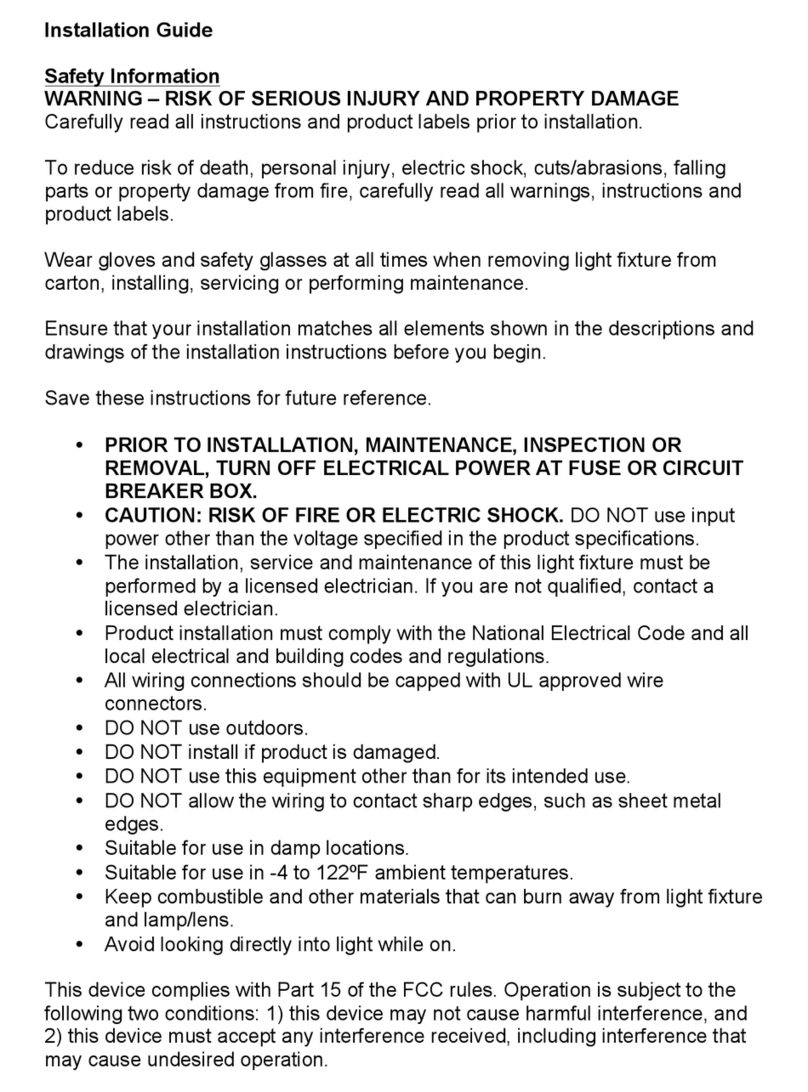
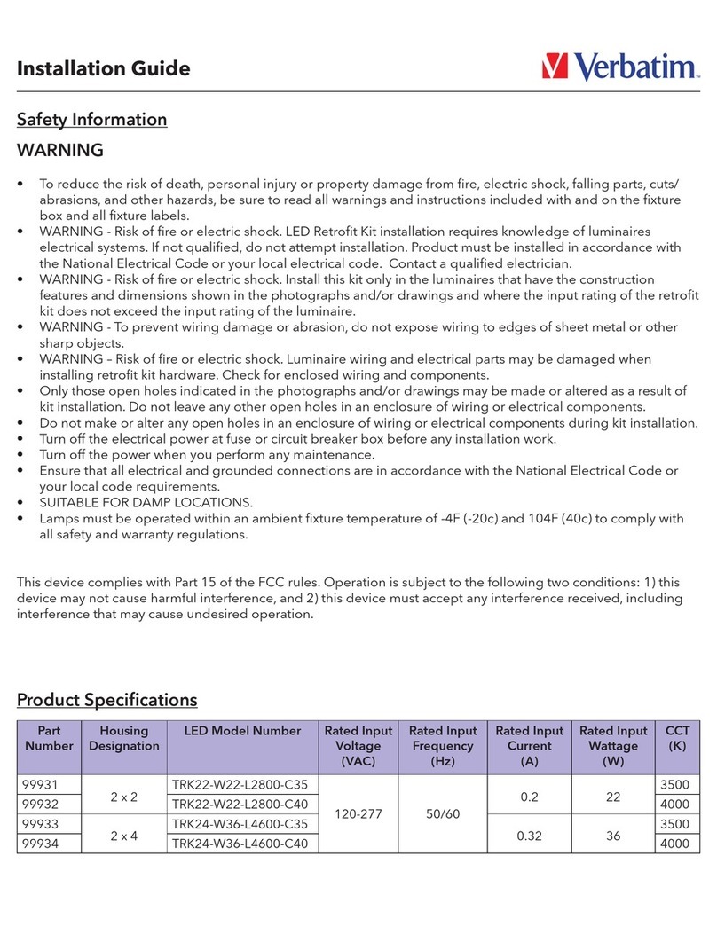
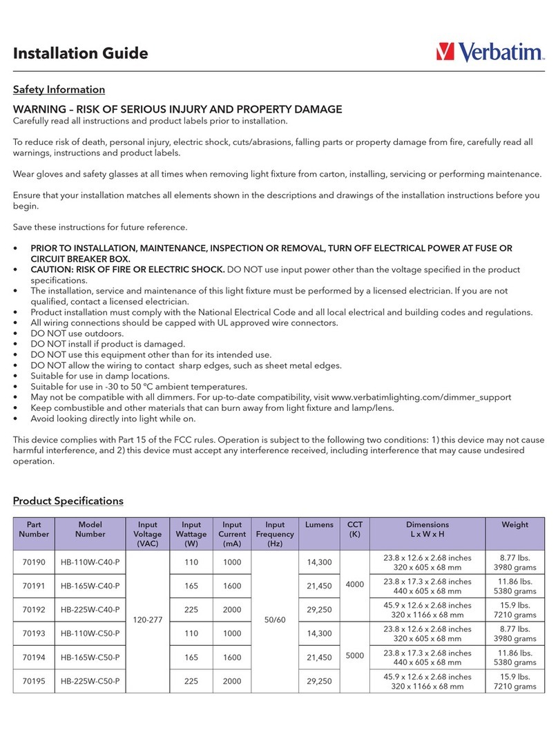
Important Safety Instructions
WARNING – RISK OF SERIOUS INJURY AND PROPERTY DAMAGE: Carefully read all instructions and
product labels prior to installation.
• WARNING- Risk of re or electric shock. The installation, service, and maintenance of this light xture
must be performed by a licensed electrician. If you are not qualied, contact a licensed electrician.
• Product installation must comply with the National Electrical Code and all local electrical and building
codes and regulations.
• Do NOT install if product is damaged.
• Prior to installation, maintenance, inspection or removal, turn off electrical power at fuse or circuit
breaker box.
• Do NOT use input power other than the voltage specied on the Product Specications.
• All wiring connections should be capped with UL approved wire connectors.
• Ensure that your installation matches all elements shown in the descriptions and drawings of the
installation instructions before you begin.
• Do NOT make or alter any openings in the housing, enclosure of wiring or electrical components of the
light xture during installation.
• Do NOT allow the wiring to contact sharp edges, such as sheet metal edges.
• Wear gloves and safety glasses at all times when removing light xture from carton, installing, servicing,
or performing maintenance.
• Avoid looking directly into light while on.
• Keep combustible and other materials that can burn away from light xture and lamp/lens.
• Suitable for use in damp locations.
• Ensure that the light xture operates within an ambient temperature of -4ºF to 104ºF (-20ºC to +40ºC).
• THIS PRODUCT MUST BE INSTALLED IN ACCORDANCE WITH THE APPLICABLE INSTALLATION
CODE BY A PERSON FAMILIAR WITH THE CONSTRUCTION AND OPERATION OF THE PRODUCT
AND THE HAZARDS INVOLVED.
Verbatim 5 year warranty www.verbatimlighting.com/warranty.
For support, visit www.verbatimlighting.com/support
This device complies with Part 15 of the FCC rules. Operation is subject to the following two conditions:
1) this device may not cause harmful interference, and
2) this device must accept any interference received, including interference that may cause undesired
operation.
Part No. Model Number Cut-out Hole
70663 TR2-WB-RO 3 in.
70664 TR2-BB-RO 3 in.
70665 TR2-WG-RO 3 in.
70666 TR2-WB-RO-EL 3 in.
70667 TR2-WB-RO-PH 3 in.
70668 TR2-WB-SQ 3 in.
70669 TR2-WB-SQ-WW 3 in.
70670 TR2-DW-RO 3.5 in.
70671 TR2-SW-RO 3 in.
70672 TR2-SB-RO 3 in.
TrimsProduct Dimensions
To lock gimbal settings, tighten screws on side of trim.


