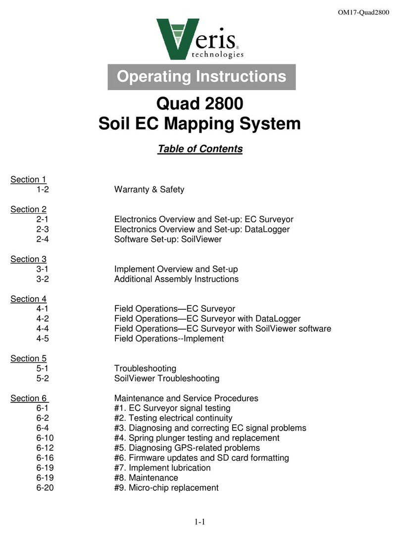
Veris P4000 User manual

2-1
P4000 DW-EC-Force Probe
Table of Contents
Section 1
1-1 Warranty & Safety
Section 2
2-1 System Overview P4000
2-3 System Overview Electronics
2-10 Model Year 2018 and newer Electronic additions
2-11 Procedure # 1 Establishing Bluetooth Connectivity
Section 3
3-1 Software Installation Guide
Section 4
4-1 Field Operations –Electronics
Section 5
5-1 Probe Platform Installation—skid units
5-3 Platform Operation
5-4 DW-EC-Force Probe Operation
5-6 Soil Coring
5-8 Soil Anchoring System
5-10 Probe Removal and Tractor Installation
Section 6
6-1 Maintenance and Lubrication
6-4 Probe Removal
6-5 Instrument Removal
Section 7
7-1 Troubleshooting
Section 8
8-1 Specifications
Operating Instructions

2-2
Warranty
Veris Technologies warrants this product to be free of defects in materials and
workmanship for a period of one (1) year from the date of delivery to the purchaser.
Veris Technologies will repair or replace any product returned to Salina, Kansas, which
appears upon inspection to be defective in materials or workmanship. Veris
Technologies will have shall have no obligation under this warranty for the cost of labor,
down-time, transportation charges, or for the repair or replacement of any product that
has been misused, carelessly handled, modified, or altered.
ALL OTHER WARRANTIES OF ANY KIND, WHETHER EXPRESSED OR IMPLIED,
INCLUDING BUT NOT LIMITED TO ANY IMPLIED WARRANTY OF
MERCHANTABILITY OR OF FITNESS FOR A PARTICULAR PURPOSE AND ALL
CLAIMS FOR CONSEQUENTIAL DAMAGES, ARE SPECIFICALLY DISCLAIMED AND
EXCLUDED.
Safety

2-3
Important! Read the following SAFETY PROCEDURES before operating the Veris
P4000
• Probing into buried electrical, gas, sewer, communication and other utilities can cause
death, serious injury, and significant property loss. Utilize ‘call before you dig’ services.
• Pinch point hazard: to prevent injury, stand clear when raising or lowering any part of
the Veris P4000.
• Install all transport locks before transporting or working underneath.
• Detach and store implements in an area where children normally do not play. Secure
implement by using blocks and supports.
• Keep feet clear of foot and probe when lowering.
• Do not probe where utility lines may be present. Use ‘Call Before You Dig’ services.
• Use paper or cardboard, NOT BODY PARTS, to check for suspected leaks.
• Wear protective gloves and safety glasses or goggles when working with hydraulic and
high-pressure wash systems.
• If an accident occurs, see a doctor immediately. Any fluid injected into the skin must
be surgically removed within a few hours or gangrene may result.
• Read Operations Manual before operating machine
• Review safety instructions with operators before operating machine and at least
annually
• Riders obstruct the operator’s view. They could be struck by foreign objects or
thrown from the machine.
• Never allow children to operate equipment.
• To prevent possible electrical shock, or damage to the instrument, do not connect to
any power source greater than twelve (12) volts DC.
• Do not grease or oil implement while it is in operation.
• Disconnect battery ground cable (-) before servicing or adjusting electrical systems or
before welding on implement.
• Remove buildup of mud, oil or debris.
• Be prepared if a fire starts
• Keep a first aid kit and fire extinguisher handy.
• Be careful when touching the probe after use, the sapphire window gets hot.
Section 2

2-4
VERIS P4000 Probe Platform
System Overview
Before you begin using your P4000, it’s important to familiarize yourself with the basic
components and controls
Pre-operation checks:
1) Engine oil Level –refer to Honda GX 670 engine manual
2) Hydraulic fluid -- fluid level should be at or near upper black line on sight gauge
of hydraulic reservoir. (Figure 1). If not add suitable ISO 32 hydraulic fluid with a
viscosity index of 95- 140. Unit is filled at factory with Mobilfluid 424.
3) Check gas level –unleaded gasoline only
4) Check for any loose fasteners or hydraulic leaks.
Controls:
1) Engine controls are located on the engine itself. (figure 2) . Refer to Honda
engine manual for detailed information.
Hyd sight
gauge
Fuel Tank
Figure 1
Starter Switch
Choke
Throttle
Figure 2

2-5
Hydraulic Controls
All system monitoring and probe control functions are contained on the
console mounted to the right of the probe, referred to as the “foot”. (Figures 3,4)
a) Voltage meter –monitors battery voltage
b) Side shift control –allows lateral movement of probe for multiple insertions at
a given location.
c) Extension control -- used to extend probe from transport to field use position
d) Fold control –folds probe from transport to use position
e) Probe speed flow control –controls insertion speed of NIR/EC Force Probe to
operator preference
f) Hydraulic pressure gauge –monitors system pressure during hydraulic
cycling
g) Hour meter—monitors engine operation for routine maintenance
h) Foot Control –Raises and lowers foot
i) Rotation control –aids in soil core insertion in tough soils. Down is clockwise-
direction required for coring.
j) Probe control –Raises and lowers probe assembly
k) Engine emergency stop –immediately shuts down engine if need arises.
l) 12VDC power switch for OpticMapper Instrument.
Figure 3
Figure 4
Voltage meter Side Shift control Extension control Fold control
Probe speed
Flow control
12v power switch Engine emergency stop Probe control Rotation control Foot control
Hyd pressure gauge
Engine hour meter

2-6
Electronics
System diagram
Figure 7

2-7
OM Com/GPS Input
Serial communication to PC and GPS
input with cable #49494
12V Power
Power cord shipped with the unit that
connects to the vehicle’s battery
On/Off
Turns power to
OpticMapper
Controller
On/Off
3A Fuse
Power
Indicator
Indicates when
power to the
controller is on
Trigger
Sets starting
depth point on
when logging
Depth
Stringpot cable
connects here
to track probe
depth
EC
Connects to EC
connection
coming from
probe
Optic Power
Delivers
power to LEDs
and receives
the force
signal input
Figure 8
Figure 9

2-8
Figure 12
Figure 13
Cable that includes force, EC and
optical connections
Garmin GPS
# 21221
Power cable
#39985
This is used to power the
instrument from a vehicle (for
field use).
Note: Only use 5-amp fuse
Garmin external GPS
Note: for model years 2018 and
newer this is not supplied as there
is an internal GPS source on the
V.Sense Controller
Optical sensor
Electrical Conductivity (EC) contacts
Figures 10 & 11

2-9
String Pot #SC160
String Pot Cable
Connects stringpot to
instrument
USB-Serial
Converter
Figure 15
Optical testload
connects to
Optical port on
instrument to
simulate optical
readings to test
instrument
EC testload
connects to EC port
on instrument to
simulate EC readings
to test instrument
EC Dipole tester
connects between
the brass pin and EC
tip to simulate EC
readings
OM Reference block
Used to simulate light
and dark readings for
optical sensor
Figure 14

2-10
Model Year 2018 and newer Electronic additions
2018 and newer model years use a V.Sense controller in place of the EC OM
Controller. This offers similar functionality; however there is the addition of a Bluetooth
connection, and internal GPS. The controller will default to use the internal GPS signal;
however if an external GPS signal is provided via the GPS input connector then the
external signal takes priority. See the Bluetooth pairing (procedure #1 on following
page) for additional information on Bluetooth connectivity.
Note: No connection is necessary for the U3 COMM Port when using the V.Sense
Controller
GPS
Bluetooth
Antenna
Figure 16

2-11
Procedure # 1 Establishing Bluetooth Connectivity
The V.Sense controller is equipped with a class 1 Bluetooth ® connectivity, capable of
communicating at distances of 150 feet, and eliminating the need for a physical
connection to the PC. Follow the directions below to establish this connection.
Click the Bluetooth icon in the lower
right hand corner of the task menu
Select Add a Bluetooth Device
The serial number of the V.Sense controller will appear as Ready to pair; Select Pair
Figure 17.1
Figure 17.2
Figure 17.3

2-12
Enter the passcode 1234,
then select Next
V.Sense controller will
show Connected and be
ready for use
Figure 17.4
Figure 17.5

3-1
Section 3
Software Installation and Setup
Software Installation
Note: For computers outside the United States of America, please make the following
change to the computer’s regional settings before installing the Veris
Spectrophotometer Software.
Step 1: Open control panel and double click on Regional and Language Options
Step 2: Click on Customize, the following screen will appear. The Decimal symbol
needs to be a “.” while the Digit grouping symbol needs to be a “,”. The will ensure
proper operation of the software. Once the changes have been made click OK and
proceed with installation.
Veris DW-EC - Force Software Installation
Figure 1
The Veris DW-EC -
Force Software
installer will guide the
user through
installation of the Veris
operating software and
the necessary drivers
needed to use the
USB-Serial converter

3-2
Figure 2
Figure 3
Only install
software in the
default
directory..

3-3
Figure 4
Click next to install
software
Click finish to exit installer
Figure 5
Figure 6

3-4
Veris SoilViewer will now install drivers
necessary to operate the included USB-
Serial Converter (part #41377). If you do not
want to use the included converter than press
cancel here, otherwise click Next.
Figure 7

4-1
Section 4
Field Operation - Electronics
The DW Force EC probe software will acquire a red reflectance, IR reflectance, EC, and
force measurement for every 2cm the probe is inserted. Before opening software, turn
on power to the OpticMapper EC Surveyor Controller and connect via serial cable to the
PC. To begin data acquisition open the software and select a file to be saved. Note:
File can be appended to if necessary, by selecting an exsisting file.
Once a file is selected the software will search for connectivity with the instrument.
After the connection is established the Port light will turn green. If no connection is
made, the light will remain red. If no green light is given, check for 12V to the
instrument and ensure the serial or USB to serial cable is connected or if using a model
2018 controller and the Bluetooth connection, ensure it is properly paired via procedure
#1. If a connection can still not be established, then unplug the serial or USB to serial
cable, shut down power to the instrument, and restart the software. If no connection is
made still, then unplug the serial or USB to serial cable and restart the computer. Once
the computer is back up, plug in the serial or USB to serial cable and open the software
again.
Any name or number can be used for
the file name
After typing name click save to
continue
Figure 1

4-2
.
Depth will be -1
until trigger is
pressed.
Figure 2
Figure 3
Figure 6
Place the probe tip at the desired starting point
(typically set the EC tip in the top 2” of soil
so the tip is covered in the soil; be
consistent in starting point in order to make
accurate comparisons across multiple
insertions), check to ensure the GPS signal is
received, push the trigger button (only after the
probe is at the desired starting position, the
depth reading on the screen will change from
-1 to 0.00, and the trigger light will turn green
after being pressed), press log or hit Enter and
begin inserting the probe to store data. The log
light will turn green indicating the software is in
log mode.
After pressing the trigger button the
trigger light will turn green on the
screen and depth will show 0.00
(see figure 5)
Figure 4
Figure 5

4-3
Data is collected and averaged every 2cm. Once a 2cm interval is reached the data light will
flash and the data is written to the output file. After reaching the desired depth pull the probe
out and the trigger will automatically reset, and logging will stop. The trigger will need to be
initialized, and log button pressed again to start sampling at another location. The probe # will
increment with each log insertion.
The EC readings will give the following error codes:
-1 = Low Current this condition should occur when the probe is out of the ground
-2 = Low Voltage this condition occurs when the dipole is shorted. Check EC tip isolation
under the troubleshooting section
-4 = High Voltage this condition occurs when the dipole is open. Check EC tip isolation
under the troubleshooting
Figure 9 Example log output file. Data is stored in as a .DAT file (tab delimited text)
Figure 7
Figure 8

5-1
Section 5
Field Operation
Installation: P4000-S (skid-mount)
The P4000-S is designed to be installed in ¾ ton –1 ton pickups. Due to the wide range
of bed and frame dimensions on the market, there are no mounting holes in lower frame
flange. Some drilling and fabrication will be required. You may choose to perform this
on your own, or may wish to have a local welding or truck shop do this for you.
Steps:
1) Properly lift probe assembly in folded position with a minimum of two nylon straps
and lower into pickup bed.
2) Center side-to-side in bed and so rear portion of skid frame rail is 14” forward of
farthest point on rear bumper (Figure 1). This will ensure that foot will not contact
bumper when the skid is in the retracted position.
3) Ideally 4 mounting bolts (½” Gr5) are adequate for fastening the probe skid to the
frame of the truck. Choose mounting location based on frame obstructions such
as spring hangers, fuel tank hoses, etc. This will take some time, measuring both
top and underneath the bed to make sure bolts will align with skid frame
4) Locate all four positions and fabricate “L” straps from at least 3/8” material and
bolt or weld to frame. Make sure that fuel tanks, fuel line, and brake lines are not
in danger of being drilled or welded. Drilling is preferable and two ½” bolts in the
vertical position are adequate. (Figure 2)
Figure 1
14” from rear edge
to rear of bumper
Table of contents
Other Veris Farm Equipment manuals
Popular Farm Equipment manuals by other brands

Titan Attachments
Titan Attachments ADJDISCP2 Operator's manual

Sulky Burel
Sulky Burel X40+ ISOBUS Technician's Operating Manual

Demco
Demco 365 WAGON Operator's manual

MacDon
MacDon A30-S Assembly instructions

Bayer HealthCare
Bayer HealthCare SeedGrowth 80996381 user manual

Land Pride
Land Pride BS10 Operator's manual