manuals.online logo
Brands
  1. Home
  2. •
  3. Brands
  4. •
  5. Veris
  6. •
  7. Farm Equipment
  8. •
  9. Veris U3 User manual

Veris U3 User manual

Other manuals for U3

1

Other Veris Farm Equipment manuals

Veris iScan User manual

Veris

Veris iScan User manual

Veris iScan EC-OM User manual

Veris

Veris iScan EC-OM User manual

Veris Quad 2800 Soil EC Mapping System User manual

Veris

Veris Quad 2800 Soil EC Mapping System User manual

Veris 3150 MSP3 User manual

Veris

Veris 3150 MSP3 User manual

Veris P4000 User manual

Veris

Veris P4000 User manual

Veris U3 User manual

Veris

Veris U3 User manual

Popular Farm Equipment manuals by other brands

Schaffert Rebounder Mounting instructions

Schaffert

Schaffert Rebounder Mounting instructions

Stocks AG Fan Jet Pro Plus 65 Original Operating Manual and parts list

Stocks AG

Stocks AG Fan Jet Pro Plus 65 Original Operating Manual and parts list

Cumberland Integra Feed-Link Installation and operation manual

Cumberland

Cumberland Integra Feed-Link Installation and operation manual

BROWN BDHP-1250 Owner's/operator's manual

BROWN

BROWN BDHP-1250 Owner's/operator's manual

Molon BCS operating instructions

Molon

Molon BCS operating instructions

Vaderstad Rapid Series instructions

Vaderstad

Vaderstad Rapid Series instructions

HighLine BM1400 operating manual

HighLine

HighLine BM1400 operating manual

GSi PNEG-2314 installation manual

GSi

GSi PNEG-2314 installation manual

Checchi & Magli TEXDRIVE owner's manual

Checchi & Magli

Checchi & Magli TEXDRIVE owner's manual

Amazone Cenius 4003-2TX operating manual

Amazone

Amazone Cenius 4003-2TX operating manual

MASSEY FERGUSON MF 9313S Operator's manual

MASSEY FERGUSON

MASSEY FERGUSON MF 9313S Operator's manual

Cima BLITZ Maintenance Instruction

Cima

Cima BLITZ Maintenance Instruction

Amazone CombiDisc 3000 Original operating manual

Amazone

Amazone CombiDisc 3000 Original operating manual

HE-VA Disc-Roller XL Contour Operating instructions/spare parts list

HE-VA

HE-VA Disc-Roller XL Contour Operating instructions/spare parts list

AGT AGT-SSFM product manual

AGT

AGT AGT-SSFM product manual

Milestone 72-84 manual

Milestone

Milestone 72-84 manual

KUHN Hector 3000 Complementary instructions

KUHN

KUHN Hector 3000 Complementary instructions

Krone X-Disc 6200 operating instructions

Krone

Krone X-Disc 6200 operating instructions

manuals.online logo
manuals.online logoBrands
  • About & Mission
  • Contact us
  • Privacy Policy
  • Terms and Conditions

Copyright 2025 Manuals.Online. All Rights Reserved.

Veris U3 12-Volt Electrical System Troubleshooting Guide
The 12V power system for the U3 performs several functions: 12V power is required for collecting soil
EC, optical, and pH sensor readings. 12V power is also required to raise and lower the implement, insert
and retract the pH sampler, and to wash the pH electrodes after each measurement cycle. The entire
system includes controllers, solenoids, proximity sensors, and other components that are designed to
function in concert with each other. If 12V power is inadequate or interrupted, or if any of the
components isn’t functioning properly, the system will not perform its tasks. This troubleshooting guide
provides an overview of the system and its components, and step-by-step instructions on how to
diagnose and correct any problems that occur.
Contents:
12V System Overview P.1
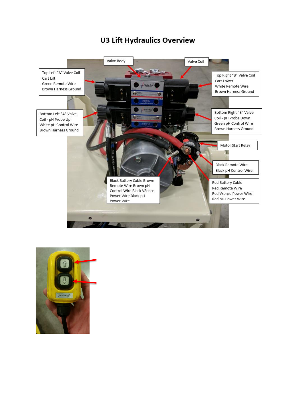
U3 Lift Hydraulics Overview P.2
pH Sampler doesn’t move properly when in manual mode P.2
pH System doesn’t cycle in automatic mode, but ok in manual mode P. 4
pH System cycling is intermittent or erratic P. 14
Figure 1
Figure 2
Figure 3
Remote, which controls the implement wheels.
Note orientation (wire out the bottom)
Up
Down
If pH sampler or lift cycler doesn’t move in manual mode or only moves one direction.
A. Does the motor run and maintain above 10V?
Check for adequate voltage good connections to the battery, and hydraulic pump. Is there 10V at the
motor while running the hydraulics?
Rev engine if necessary to maintain voltage above 10V while testing.
C. Check the LED on din connectors—this indicates signal is reaching coil to engage the valve.
If the appropriate LED indicator doesn’t light up when the hydraulics are engaged, there could be a
broken wire in the harness, or less than adequate voltage to engage the coil.
Cart Lift
Cart Lower
pH probe down
pH probe up
LED on the clear Din connector will
light up when each hydraulic function
is enabled.
Figure 5
Figure 6—Valve Function
Figure 4
C. Manually engage the valve.
The coil may not be getting enough voltage to open the valve, or the valve could be stuck. Try to
manually engage the valve by pressing manual indent while engaging the motor (engage the motor by
pressing the up or down function on the yellow remote, or pressing the manual up or down function of
on the pH controller—engage the motor using based on which function you’re trying to replicate)
If it moves, then check coil resistance, and low power condition. Replace coil if ohm reading shows open,
or above 8ohms.
Check the top and bottom
prongs on the coil. Standard
resistance is 4 ohms.
Press the indent on the valve appropriate valve function;
See figure 6
Simultaneously press the indent and
engage the motor using the
standard hydraulic remote, or U3
pH controller UP/Down switch
Figure 7a and 7b
Figure 8
If intended hydraulic function doesn’t move by pressing indent, but the opposite function does (ex. the
pH doesn’t move up or down; however, the wheel lift does), then swap valve bodies
If after swapping the valve bodies the issue persists, the issue could be related to the internal check
valve—contact Veris support.
Remove the two allen screws holding valve
body in place, swap with the alternate valve
(top is cart lift, bottom is pH probe lift), and
see if the issue follows the valve body, if so
contact Veris Service department and order
material# 113003
Figure 9
Unit doesn’t cycle in automatic mode, but cycles ok in manual mode.
In order for the pH system to cycle automatically, several conditions must be met: consistent
communication between the tablet PC and the V-Sense Controller, GPS signal received, positive EC
values, a minimum distance from previous sample, and adequate 12 volt power.
Figure 10. Conditions for pH sampling to initiate
Positive EC
readings
Single sample
can be taken any
time; automatic
sampling
requires a
minimum
distance
Communication
between tablet
PC and V-Sense
controller
pH sampler must
be in up position
to initiate
sampling
GPS or DGPS or RTK
A. Is EC/OM communication light green, showing communication between V.Sense controller and PC?
Troubleshooting USB/Serial Connections
1) Ensure the OM Com cable is securely connected to the OM Com port, then that the serial Output is
connected to the USB to Serial Converter, and lastly that the USB cable is connected to the PC.
3) Check the device manager for a known USB COM port listed under the ports section. Unplug and
replug the USB cable, and the COM port should disappear and reappear. The Device Manager can be
accessed by right clicking on the windows icon , and selecting Device Manager. If no COM port is
present under the ports section, then the driver is missing, see Installing USB/Serial Converter procedure
#.
Figures 11-13
Figure 14
2) Force the USB port to reset, by shutting down the software and the
V.Sense controller, unplug the USB cable, and restart the PC. Only plug
the USB cable back in after the PC is fully reset. Once restarted, turn on
the V.Sense, plug in the USB, and open SoilViewer. Be sure to follow
this order of operations, and use the Windows restart option
Figures 16
Figure 15
4) The COM Port is available; however, it still doesn’t connect automatically. The port can be set
manually in SoilViewer. Use the drop-down arrow to select the COM value shown in the device
manager. Note: for U3 systems you’ll only assign an OM/EC Com
After setting the port, check SoilViewer for communication (green OM/EC Com light, and sensor
readings showing on screen).
5) After attempting to set the port manually, if there is still no OM/EC Com shown on the SoilViewer
Screen, then open the V.Sense controller, and check for a red blinking light. Be careful when removing
the lid—there’s a circuit board mounted to the top.
Figure 17
Figure 18
Figure 19 Showing the red light which will blink to indicate data is being sent out of the controller.
Note: If there’s a green blinking light as well, that’s indicating GPS signal is reaching the controller
Red Blinking Light Present on Controller:
If there’s a red blinking light, then controller is working properly, and the issue is external of the V.Sense
box. Check the following
1) Test OM COM serial cable for continuity (see figure 20),
2) Try another USB/Serial converter
3) Use a different PC if available
4) Switch to Bluetooth Connection.
No Red Blinking Light Present on Controller
If there is no red blinking light then, unplug all connections to the V.Sense controller, except the 12V
power. Power cycle the V.Sense controller, and check for the red light. If the red light is not present
contact Veris Support. If the red light begins to blink, then an external cable is shorted causing the
controller to malfunction. Plug in each cable one at a time, and check for the light to turn off which
would indicate the faulty component.
Figure 20
Troubleshooting Bluetooth connections
1) Ensure the Bluetooth is properly paired using procedure #.
2) Check that the antenna is installed
3) If the controller is paired and still not connecting, restart the PC with the V.Sense controller
turned off. Once the PC is turned back on, power on the V.Sense controller, and start SoilViewer
to try again.
4) Unpair any other devices which may be connected to your PC.
5) Unpair the device (figure 31 below), and repair using procedure #11 from Operations Manual.
6) Swap to USB/Serial Connection and follow troubleshooting steps listed for Troubleshooting
USB/Serial Connections, if no USB/Serial Converter connection is possible, then see step 5 of
Troubleshooting USB/Serial Connections
Figure 30
Figure 31