Veris 3150 MSP3 User manual

Pub. # OM20-MSP3-3D
3150 or 3210 MSP3
Table of Contents
Section 1
1-1 Warranty
1-2 Safety
1-4 FCC Note
1-5 Declaration of Conformity
1-6 Statement of Use
1-7 Lift Procedure
Section 2
2-1 Electronics Overview and Set-up
2-4 Software Setup: SoilViewer
Section 3
3-1 Implement Overview and Set-up
Section 4
4-1 Field Operations: SoilViewer, OM and pH system checks
4-10 Field Operations: EC and OpticMapper
4-19 Field Operations: pH Manager
4-26 Mapping with SoilViewer
Section 5
5-1 Maintenance and Service: EC
5-3 Maintenance and Service: OpticMapper
5-6 Maintenance and Service: pH
Section 6 Service and Troubleshooting Procedures
6-2 #1 OM Signal Testing
6-3 #2 EC Signal testing
6-4 #3 Testing electrical continuity
6-6 #4 Diagnosing and correcting EC signal problems
6-12 #5 Spring plunger testing and replacement
6-14 #6 Diagnosing GPS-related problems
6-18 #7 Bearing replacement
6-19 #8 Soilviewer troubleshooting
6-20 #9 Optical Wear plate and Side Wear plate replacement
6-21 #10 pH Toubleshooting
6-26 #11 Checking External Controller Power
6-29 #12 Sampler Cylinder Hydraulics
6-32 #13 pH Communication Problems
6-37 #14 Prox Sensor
6-42 #15 Establishing Bluetooth Connectivity
Operating Instructions

Pub. # OM20-MSP3-3D
1-1
MSP3 (3150 or 3210)
SoilViewer Version 2.66.3
Section 1
Warranty
Veris Technologies warrants this product to be free of defects in materials and workmanship for a
period of one (1) year from the date of delivery to the purchaser. Veris Technologies will repair or
replace any product returned to Salina, Kansas, which appears upon inspection to be defective in
materials or workmanship. Veris Technologies shall have no obligation under this warranty for the
cost of labor, down-time, transportation charges, or for the repair or replacement of any product
that has been misused, carelessly handled, modified, or altered.
ALL OTHER WARRANTIES OF ANY KIND, WHETHER EXPRESSED OR IMPLIED, INCLUDING
BUT NOT LIMITED TO ANY IMPLIED WARRANTY OF MERCHANTABILITY OR OF FITNESS
FOR A PARTICULAR PURPOSE AND ALL CLAIMS FOR CONSEQUENTIAL DAMAGES, ARE
SPECIFICALLY DISCLAIMED AND EXCLUDED.
Safety

Pub. # OM20-MSP3-3D
1-2
Important! Read the following SAFETY PROCEDURES before operating the Veris system:
• Read and understand all instructions on safety decals
• Escaping fluid under pressure can penetrate the skin causing serious injury. Avoid the hazard
by relieving pressure before disconnecting hydraulic lines. Use a piece of paper or card-board,
NOT BODY PARTS, to check for suspected leaks.
• Wear protective gloves and safety glasses or goggles when working with hydraulic and high-
pressure wash systems.
• If an accident occurs, see a doctor immediately. Any fluid injected into the skin must be surgically
removed within a few hours or gangrene may result.
• Pinch point hazard: to prevent injury, stand clear when raising or lowering any part of the Veris
implement.
• Install all transport locks before transporting or working underneath.
• Detach and store implements in an area where children normally do not play. Secure implement
by using blocks and supports.
• Read Operations Manual before operating machine
• Review safety instructions with operators before operating machine and at least annually
• Never stand on or use tire as a step
• Do not tow the implement on public roads without the road-kit light package, or without the proper
safety equipment and licensing as required by your State Department of Transportation. Always
use safety chain.
• Riders obstruct the operator’s view. They could be struck by foreign objects or thrown from the
machine.
• Never allow children to operate equipment.
• To prevent possible electrical shock, or damage to the instrument, do not connect to any power
source greater than twelve (12) volts DC.
• Do not grease or oil implement while it is in operation.
• Disk edges are sharp. Be careful when working in this area.
• Disconnect battery ground cable (-) before servicing or adjusting electrical systems or before
welding on implement.
• Remove buildup of mud, oil or debris.
• Be very careful when mapping stubble fields with a gasoline engine vehicle. Be prepared if a fire
starts.
• Keep a first aid kit and fire extinguisher handy.

Pub. # OM20-MSP3-3D
1-3
Excess speed, especially when turning could cause overturning.
Never pull units faster than 15 km/hr.
Use caution when working on implement. Coulter disks are sharp and may
causes cuts.
Don’t allow anyone to climb or ride on implement
The vehicle that pulls the Veris unit thru the field will get hot! There is a chance that
this heat can cause field fires in stubble fields.
Don’t lower unit while any part of body is underneath

Pub. # OM20-MSP3-3D
1-4
Keep safety chain installed
Install jack before unhitching; do not drop unit on foot
FCC NOTE
This equipment has been tested and found to comply with the limits for a Class A digital device,
pursuant to Part 15 of the FCC Rules. These limits are designed to provide reasonable protection
against harmful interference when the equipment is operated in a commercial environment. This
equipment generates, uses, and can radiate radio frequency energy and, if not installed and used
in accordance with the instruction manual, may cause harmful interference to radio
communications. Operation of the equipment in a residential area is likely to cause harmful
interference in which case the user will be required to correct the interference at this own expense.

Pub. # OM20-MSP3-3D
1-5
EUROPEAN DECLARATION OF CONFORMITY
Veris Technologies, Inc., located at 601 N. Broadway in Salina Kansas, certifies that the product:
Veris MSP3-3D
is in conformity with the following directive and standards:
Machinery Directive 2006/42/EC--1st Edition—December 2009
Electromagnetic Compatibility 2004/108/EC —December 2004
EN55022 –Measuring Radiated Emissions
The Technical File is maintained at:
Veris Technologies, Inc.
601 N. Broadway
Salina KS 67401
Date of issue: May 1, 2012
Place of issue: Salina KS USA

Pub. # OM20-MSP3-3D
1-6
Statement of Use
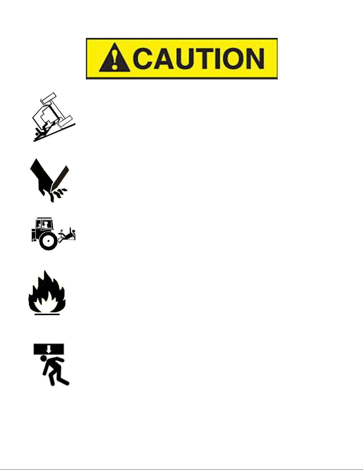
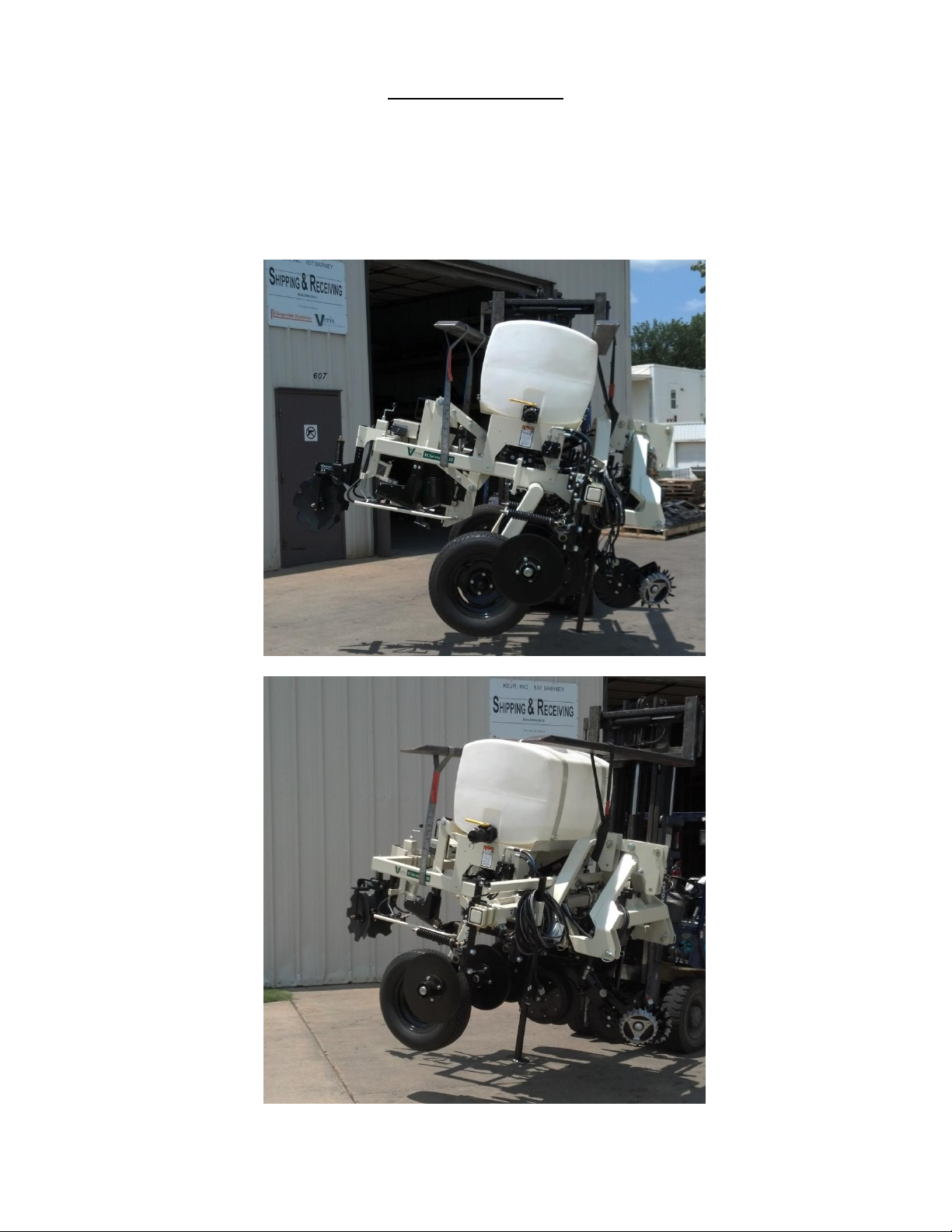
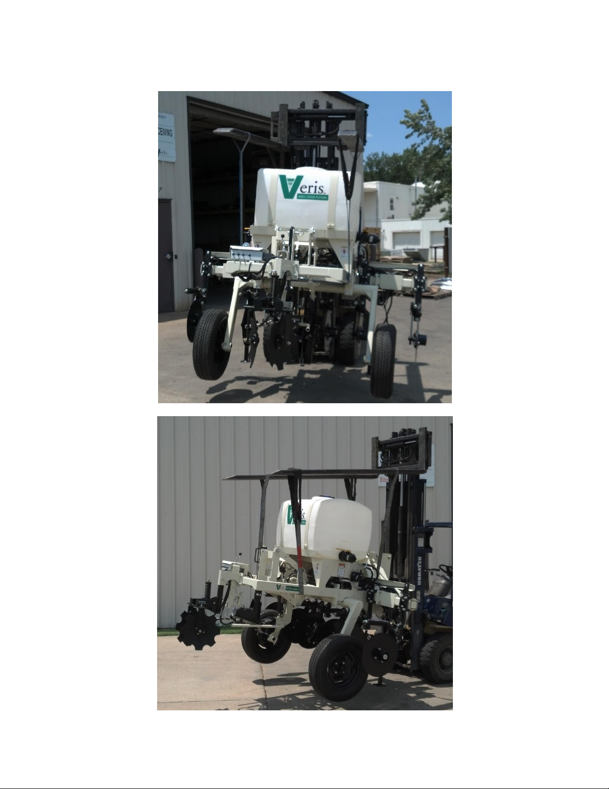
Intended use of the Veris MSP3 model
The Veris MSP3 Soil EC, Organic Matter, and pH Mapping System collects geo-referenced soil
electrical conductivity (EC), soil reflectance, and soil pH measurements as it is pulled across a field
by a tractor. An electronic device called the Soil EC Surveyor, powered by vehicle’s 12V DC
electrical system, generates a small electrical current, which is transferred into the soil through a
pair of rolling electrode coulter disks. A second pair of disks measures the drop in voltage which is
proportional to the electrical conductivity of soil medium at a given location. Signal response is due
primarily to soil texture/grain size and soil salinity. Clay soils and soils with high salinity levels are
highly conductive, while coarser soils such as sand do not conduct well. Another electronic device
called the OpticMapper controller, powered by vehicle’s 12V DC electrical system, sends power to
an optical sensor which has two wavelengths of LEDs and measures the amount of light reflected
off the soil surface with a photodiode. The optical sensor is mounted inside a standard row planter,
with two discs to cut a furrow in the soil and two depth gauge wheels to keep the sensor at
constant depth. Signal response is due to soil color, darker soils are generally higher in Organic
Matter; while lighter soils are lower in Organic Matter. A final electronic device called the pH
controller, powered by vehicle’s 12V DC electrical and hydraulic system, measures soil pH using
two electrodes. The pH controller cycles the pH sampling shoe into the soil, where a soil core is
collected and brought up and pressed against the electrodes for a measurement. Once a stable
reading is measured, the sampling shoe moves down to collect another soil segment, and the
electrodes are washed off. This process is repeated every 20-30 seconds, as long as the operator
keeps the system engaged, and ground speed is received. The sampling shoe is controlled by
hydraulic solenoids, while the wash jets are powered by two 150 psi pumps. The system records
the data on a data recording device such as a laptop computer. Ultimately, the data are displayed
in a map format, and variable applications of crop production materials, such as seed, fertilizer and
other inputs are variably applied to the zones delineated on the maps. The MSP3-3D system is
designed for use in a farm field, and has no dynamic movement unless vehicle is pulling it, or
operator is manually activating switches, so guarding around soil engaging components is not
needed and would interfere with field operations. Unit should not be operated when people are
present in the field, as coulter disks are sharp and automated movement could cause injury if
contact occurs.
Misuse of the Veris MSP3 model
Misuses of the MSP3 model include operation with people in area, and pulling the system at an
excessive speed. In field position, this could result in poor data collection and possible tractor
overturning at extremely high speeds and sharp turns. In raised position, the chance of
overturning is increased, as the center of gravity is higher, so care must be taken to keep speeds
under 15 km/hr, and less when turning.
Abnormal use of the Veris MSP3 model
Abnormal use of the MSP3 model includes using it as a cart for carrying equipment, tools, or
people. Under no circumstances should anyone ride on the implement. Even though the
implement is similar in appearance to a tillage tool, such as a disk harrow, it was not designed for
that usage and should never be used for any purpose other than soil data collection.

Pub. # OM20-MSP3-3D
1-7
MSP3 Lifting Points
Below are the recommended lifting points for the unit. Using two straps you can safely lift the unit.
Make sure the straps used to lift are rated greater than 1200 lbs. Fork extensions maybe required
to lift. Always stay clear when lifting the unit.
Here are the proper lift points for side loading

Pub. # OM20-MSP3-3D
1-8
If lifting from front or back of the unit, use the points shown below.

Pub. # OM20-MSP3-3D
2-1
Section 2
Electronics Overview and Set-up
The MSP3-3D electronics kit shown below.
Figure 1 MSP3-3D electronics kit
Keep all diagnostics and operations manual with system when mapping.
The supplied GPS(Figure 2) is configured to operate
with the MSP3/3D electronics.
The use of any other GPS requires the correct
settings. The GPS needs to output only two NEMA
strings(GGA and VTG OR RMC). The system will
not run with more than two strings. The strings
need to output at 4800 baud and 1Hz refresh rate.
USB Serial
Adapter
MSP3/3D EC
Test Box
pH
Simulator
OM Reference
Block
OM test
load
MSP3-3D EC
test load
SoilViewer
Figure 2

Pub. # OM20-MSP3-3D
2-2
The VSense Controller is mounted on the implement, and can remain on the implement due to
weatherproofing. If the implement is stored outside for long-term storage, remove control and
store it indoors.
Figure 3 MSP3-3D Figure 4 VSense Controller
Figure 5 VSense Controller (rear)
Figure 6 VSense Controller (front)
12V Power
Power cord shipped with the unit that
connects to the vehicle’s battery
On/Off
Turns power to
OpticMapper
Controller On/Off
3A Fuse
Power Indicator
Indicates when power
to the controller is on
Optic Power
Delivers power to
Optical sensor with
cable #46222
EC Signal
Connects to EC
wire harness with
cable #49457
OM Com/GPS Input
Serial communication to PC and GPS
input with cable #49494
Depth Sensor
Connects to cable #219222
Bluetooth
Antenna

Pub. # OM20-MSP3-3D
2-3
Electronic Configuration
Soilveiwer –Connect communication cable from pH Controller to Laptop using the supplied USB to
Serial converter. Connect to VSense controller via Bluetooth. (Optional serial adapter available)
Connect EC signal cable, GPS, and power cords to the VSense controller.
Figure 7
Camera Mount –Standard hardware for the MSP3-3D includes a camera and mount. This will
allow monitoring of the pH sensor as it samples soil. The camera may need to be adjusted to
maintain optimum view of the pH sampler.
Figure 8 Figure 9
Bluetooth
Antenna

Pub. # OM20-MSP3-3D
2-4
SoilViewer
Software Setup
All 2015 models and on require SoilViewer 2.66.3 or higher.
Note: For computers outside the United States of America, please make the following change to
the computer’s regional settings before installing the Veris SoilViewer Software.
Step 1: Open control panel and double click on Region
Step 2: Click on Additional Settings, the following screen will appear. The Decimal symbol
needs to be a “.” while the Digit grouping symbol needs to be a “,”. The will ensure proper
operation of the software. Once the changes have been made click OK and proceed with
installation.
Figure 10

Pub. # OM20-MSP3-3D
2-5
Figure 11
Figure 12
Figures 13
Open Veris flash drive and double
click on setup.exe to start the
installation.
Click Next to continue through
installation
Next two license
agreements will need to
be accepted before
continuing.
Click Next to continue through
installation

Pub. # OM20-MSP3-3D
2-6
Figure 14
Figure 15
Figure 16
The installer will
install all necessary
components.
Click Next to install the USB drivers.
Click Next to continue through
installation

Pub. # OM20-MSP3-3D
2-7
Figure 17
Click Finish to complete the
installation of SoilViewer.

Pub. # OM20-MSP3-3D
3-1
Section 3
Implement Overview and Set-up
Figure 1 MSP3-3D with EC, OM, and pH sensor modules
Pinch point hazard: to prevent injury, stand clear when raising or lowering any part of the
Veris MSP3-3D.
Install all transport locks before transporting or working underneath.
Always use the service stands when working underneath the MSP3-3D.
Figure 2a Figure 2b

Pub. # OM20-MSP3-3D
3-2
12 Volt Power and Hydraulics Set-up
If the unit has been crated and delivered via closed-van commercial freight, the tongue (if
equipped) may need to be installed prior to use. Prior to operating the implement for the first time,
it is important to check all fasteners –some may have loosened during shipment. Route cables
and hydraulic hoses along tongue and through hose guide. Tie-strap securely. Connect electrical
cables to battery. Be careful to attach black cable to negative/ground terminal. DO NOT
REVERSE POLARITY.
Communication Output
GPS Input
12 V Power leads
Figure 3
Insert hydraulic ends into quick-couplers, being careful to insert the end marked “P” into the tractor
extension coupler, and the end marked “T” into the tank or return line coupler; in this configuration,
tractor’s hydraulic lever will be secured in raised position. If sampler shoe operates in reverse,
simply reverse hydraulic hoses, or secure lever in lowered position. Note: Be certain whether
tractor or hydraulic power source utilizes open or closed-center hydraulics. Damage to
tractor could occur if not set properly. The poppet knob is set ‘up’ for open systems, and
‘down’ for closed-center systems –(see settings below.) Press down and turn knob to lock down—
press down, turn and release to allow it to move up to open position.
Figure 4
Open/Closed center hydraulic poppet valve
-Up (out) for open center tractor hydraulics
-Down (in) for closed center tractor hydraulics

Pub. # OM20-MSP3-3D
3-3
Flow control settings:
Open center hydraulic systems
1) Set poppet valve in “up” raised position, this allows flow back to tank
2) Set engine at field rpm
3) Set pH controller to “Manual” and run sampling shoe up and down, timing the cycle time.
4) If sampler raises in approximately 1.5 -2 seconds, leave flow control as is, if not, rotate control
knob to achieve desired speed.
Closed center hydraulic systems
1) Set poppet valve in down position. Push down and rotate so that rolled pin locks into closed
position. This blocks flow and allows the pump to de-stroke when the directional valve is in
the neutral position.
2) Adjust flow control valve to full open position.
3) Set engine at field rpm.
4) Run sampling shoe upward and adjust raise time to approximately 1.5-2 seconds using
throttling valve on tractor’s remote coupler
Note: Excessive sampling shoe speed can damage electrodes.
Flow control valve
Adjustment control arm
Figure 5
• Escaping fluid under pressure can penetrate the skin causing serious injury. Avoid the hazard
by relieving pressure before disconnecting hydraulic lines. Use a piece of paper or card-board,
NOT BODY PARTS, to check for suspected leaks.
• Wear protective gloves and safety glasses or goggles when working with hydraulic and high-
pressure wash systems.
• If an accident occurs, see a doctor immediately. Any fluid injected into the skin must be surgically
removed within a few hours or gangrene may result.

Pub. # OM20-MSP3-3D
3-4
Flush and fill tanks with tap water; clean any foreign matter out of tank using ball valve clean-out.
Set ball valve to open position, allowing water to flow to pumps.
Figures 6a and 6b
Connecting cables to External controller as shown below:
Figure 7
ball valve:
closed
open
12 V power in
Communication
Sampler solenoid power
Prox sensor
Wash pump power
This manual suits for next models
2
Table of contents
Other Veris Farm Equipment manuals