manuals.online logo
Brands
  1. Home
  2. •
  3. Brands
  4. •
  5. Veris
  6. •
  7. Farm Equipment
  8. •
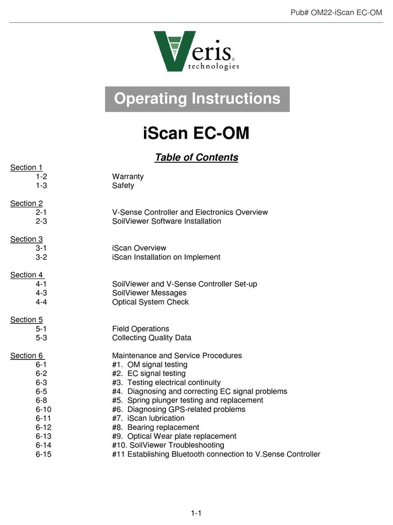
  9. Veris iScan User manual

Veris iScan User manual

1. Mount V-Sense Controller
and tighten bolts securely;
attach power and signal cables
1. Strap or chain iScan module using
lift point;
2. Lower iScan module onto mounting
bracket using aligning guides to
align module with mount.
iScan Toolbar Installation/Removal Guide (Refer to Operating Instruction Manual for complete instructions)
1. Locate 12” (30 cm)
open space on
implement toolbar
2. Install mounting bracket
using supplied U-bolts;
tighten securely
STEP I. MOUNTING BRACKET INSTALLATION
2. Connect 12 V power (battery pack, route and secure
power cables to tractor, or power port on toolbar)
1. Reverse installation process: disconnect all cables
and electronics; remove V-Sense Controller, remove
4 bolts holding iScan module to mounting bracket.
STEP IV. ISCAN REMOVAL
STEP II. ISCAN MODULE INSTALLATION
Stand clear to avoid injury
3. Attach four cross bolts
and tighten securely
STEP III. CONNECT ELECTRONICS AND 12 V POWER
2. Strap or chain iScan module
and lift from mounting bracket; if
module binds at mounting
bracket press down on closing
wheels to free up the iScan
module from mounting bracket
Stand clear to avoid injury
1. Inspect unit for loose or missing
bolts, any obvious problems
2. Clean dried soil and crop residue
from ground-engaging components
3. Lubricate fittings weekly
4. Turn on power; verify red LED is
visible through optical window
STEP I. POWER UP SYSTEM
Starting out:
While mapping:
Troubleshooting:
STEP II. OPEN SOILVIEWER PROGRAM
1. Select iScan module
2. Select file storage location and
name file/field; start new file
3. Verify communication is established
STEP III. PERFORM DAILY CHECKS
1. Check airbag: 75 psi (520 kPa)
maximum in planter raised position
2. Perform black-white reference block
test; Check wear plate and window
for excessive wear or damage.
Field Reference Guide—iScan (Refer to Operating Instruction Manual for complete instructions)
PROPER FIELD SETTINGS
All 4 iScan soil engaging components
need to be set level with good soil
contact; set coulter to cut ½” (1 cm)
deeper than other components.
Proper depth of optical sensor is 1.5-3”
(3-6 cm) with good soil contact under
window.
FIELD ADJUSTMENTS
To adjust coulter
depth, loosen front
and rear bolts;
rotate cam to raise
or lower; retighten
bolts.
Set coulter gauge wheel and closing
wheels to maintain depth; CLOSING
WHEELSARE ELECTRODES; MUST
MAINTAIN GOOD SOIL CONTACT
Map should have
pass-to-pass
repeatability with
distinct zones of
contrasting soil.
MAP MONITORING
•Observe any warnings that appear.
•When implement is raised, EC should
be -1; no EC or OM data on turnrows.
•Start new file for each field and each
day; data can be combined later
1. Check Controller12 V power; use
voltmeter if necessary.
2. Reboot tablet and V-Sense
controller.
3. Check Bluetooth pairing.
NO COMMUNICATION NOISY OR SPOTTY MAP
1. Adjust depth of iScan components;
make sure all 4 electrodes are
making good contact with moist soil.
2. Check airbag pressure: increase to
75 PSI (520 kPa) max in implement
raised position
3. If optical data shows streaks, check
window for dried mud or cracks
1. If EC isn’t -1 when unit raised: Clean
mud from iScan module; check
electrode isolation with ohmmeter
2. If EC map is noisy or readings are
jumpy: check continuity using test
box and ohmmeter
EC DATA ISSUES
Note: iScan can be locked up in storage position if interferes with planting Remember to power 12 V down at end of day!
1 2 3 4

Other Veris Farm Equipment manuals

Veris iScan EC-OM User manual

Veris

Veris iScan EC-OM User manual

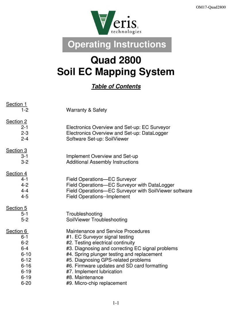
Veris Quad 2800 Soil EC Mapping System User manual

Veris

Veris Quad 2800 Soil EC Mapping System User manual

Veris U3 User manual

Veris

Veris U3 User manual

Veris P4000 User manual

Veris

Veris P4000 User manual

Veris 3150 MSP3 User manual

Veris

Veris 3150 MSP3 User manual

Veris U3 User manual

Veris

Veris U3 User manual

Popular Farm Equipment manuals by other brands

Schaffert Rebounder Mounting instructions

Schaffert

Schaffert Rebounder Mounting instructions

Stocks AG Fan Jet Pro Plus 65 Original Operating Manual and parts list

Stocks AG

Stocks AG Fan Jet Pro Plus 65 Original Operating Manual and parts list

Cumberland Integra Feed-Link Installation and operation manual

Cumberland

Cumberland Integra Feed-Link Installation and operation manual

BROWN BDHP-1250 Owner's/operator's manual

BROWN

BROWN BDHP-1250 Owner's/operator's manual

Molon BCS operating instructions

Molon

Molon BCS operating instructions

Vaderstad Rapid Series instructions

Vaderstad

Vaderstad Rapid Series instructions

HighLine BM1400 operating manual

HighLine

HighLine BM1400 operating manual

GSi PNEG-2314 installation manual

GSi

GSi PNEG-2314 installation manual

Checchi & Magli TEXDRIVE owner's manual

Checchi & Magli

Checchi & Magli TEXDRIVE owner's manual

Amazone Cenius 4003-2TX operating manual

Amazone

Amazone Cenius 4003-2TX operating manual

MASSEY FERGUSON MF 9313S Operator's manual

MASSEY FERGUSON

MASSEY FERGUSON MF 9313S Operator's manual

Cima BLITZ Maintenance Instruction

Cima

Cima BLITZ Maintenance Instruction

Amazone CombiDisc 3000 Original operating manual

Amazone

Amazone CombiDisc 3000 Original operating manual

HE-VA Disc-Roller XL Contour Operating instructions/spare parts list

HE-VA

HE-VA Disc-Roller XL Contour Operating instructions/spare parts list

AGT AGT-SSFM product manual

AGT

AGT AGT-SSFM product manual

Milestone 72-84 manual

Milestone

Milestone 72-84 manual

KUHN Hector 3000 Complementary instructions

KUHN

KUHN Hector 3000 Complementary instructions

Krone X-Disc 6200 operating instructions

Krone

Krone X-Disc 6200 operating instructions

manuals.online logo
manuals.online logoBrands
  • About & Mission
  • Contact us
  • Privacy Policy
  • Terms and Conditions

Copyright 2025 Manuals.Online. All Rights Reserved.