Veris Quad 2800 Soil EC Mapping System User manual

OM17-Quad2800
1-1
Quad 2800
Soil EC Mapping System
Table of Contents
Section 1
1-2 Warranty & Safety
Section 2
2-1 Electronics Overview and Set-up: EC Surveyor
2-3 Electronics Overview and Set-up: DataLogger
2-4 Software Set-up: SoilViewer
Section 3
3-1 Implement Overview and Set-up
3-2 Additional Assembly Instructions
Section 4
4-1 Field Operations—EC Surveyor
4-2 Field Operations—EC Surveyor with DataLogger
4-4 Field Operations—EC Surveyor with SoilViewer software
4-5 Field Operations--Implement
Section 5
5-1 Troubleshooting
5-2 SoilViewer Troubleshooting
Section 6 Maintenance and Service Procedures
6-1 #1. EC Surveyor signal testing
6-2 #2. Testing electrical continuity
6-4 #3. Diagnosing and correcting EC signal problems
6-10 #4. Spring plunger testing and replacement
6-12 #5. Diagnosing GPS-related problems
6-16 #6. Firmware updates and SD card formatting
6-19 #7. Implement lubrication
6-19 #8. Maintenance
6-20 #9. Micro-chip replacement
Operating Instructions

OM17-Quad2800
1-2
Quad 2800 Soil EC Mapping System
Soil EC Surveyor Software Version 1.2
Sensor DataLogger Version 1.03
Section 1
Warranty
Veris Technologies warrants this product to be free of defects in materials and workmanship for a
period of one (1) year from the date of delivery to the purchaser. Veris Technologies will repair or
replace any product returned to Salina, Kansas, which appears upon inspection to be defective in
materials or workmanship. Veris Technologies will have shall have no obligation under this
warranty for the cost of labor, down-time, transportation charges, or for the repair or replacement of
any product that has been misused, carelessly handled, modified, or altered.
ALL OTHER WARRANTIES OF ANY KIND, WHETHER EXPRESSED OR IMPLIED, INCLUDING
BUT NOT LIMITED TO ANY IMPLIED WARRANTY OF MERCHANTABILITY OR OF FITNESS
FOR A PARTICULAR PURPOSE AND ALL CLAIMS FOR CONSEQUENTIAL DAMAGES, ARE
SPECIFICALLY DISCLAIMED AND EXCLUDED.
Safety

OM17-Quad2800
1-3
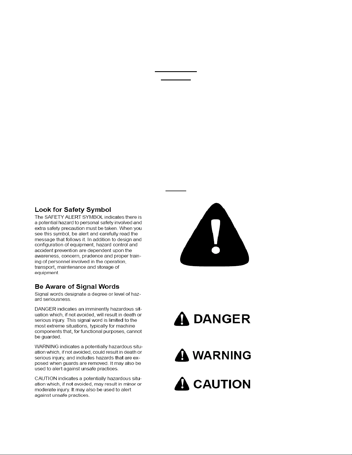
Important! Read the following SAFETY PROCEDURES before operating the Veris system:
• Read and understand all instructions on safety decals
• Properly block up implements befor working underneath.
• Detach and store implements in an area where children normally do not play. Secure implement
by using blocks and supports.
• Read Operations Manual before operating machine
• Review safety instructions with operators before operating machine and at least annually
• Never stand on or use tire as a step
• Do not tow the implement on public roads.
• Riders obstruct the operator’s view. They could be struck by foreign objects or thrown from the
machine.
• Never allow children to operate equipment.
• To prevent possible electrical shock, or damage to the instrument, do not connect to any power
source greater than twelve (12) volts DC.
• Do not grease or oil implement while it is in operation.
• Disk edges are sharp. Be careful when working in this area.
• Disconnect battery ground cable (-) before servicing or adjusting electrical systems or before
welding on implement.
• Remove buildup of mud, oil or debris.
• Be very careful when mapping stubble fields using a vehicle with a gasoline engine. Be prepared
if a fire starts. Keep crop residue and other debris from accumulating near the exhaust and in
engine compartment.
• Keep a first aid kit and fire extinguisher handy.
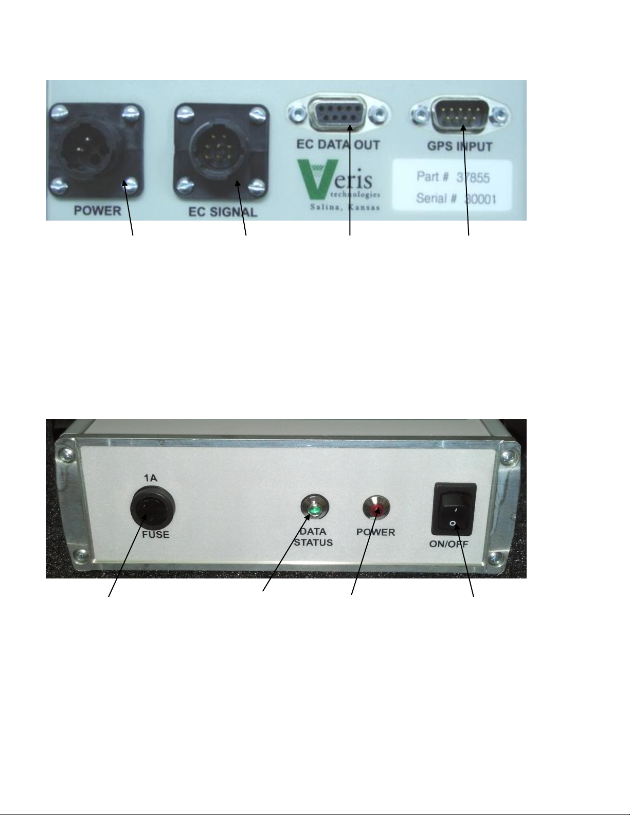
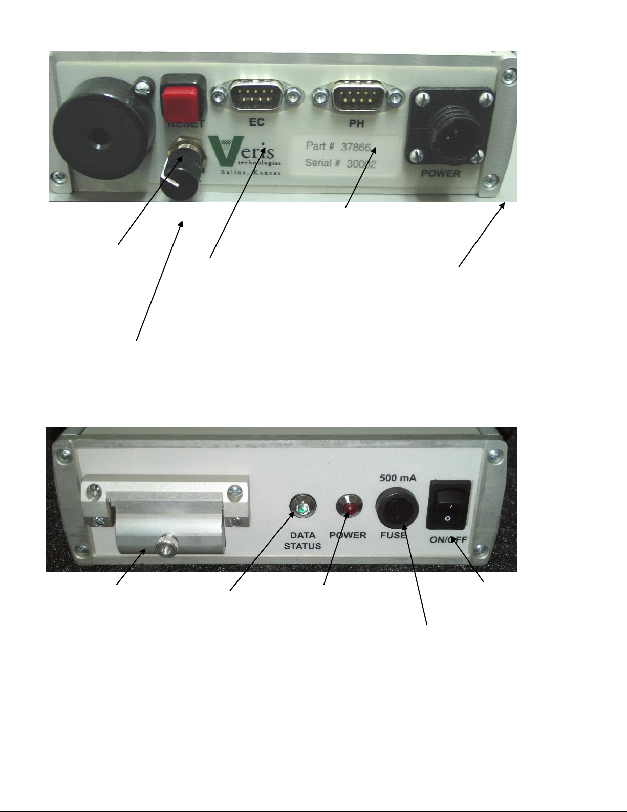
Section 2
Electronics Overview and Set-up
The Veris Electronics kits includes the following items:
Data-
Logger
Protective
case

OM17-Quad2800
2-2
Figure 1. EC Surveyor kit Figure 2. DataLogger kit
Use protective shipping/storage case to protect electronics components whenever electronics are
shipped. Keep all diagnostics and operations manual with system when mapping.
Mount instrument in a location that is as free as possible from dust, vibration, and electrical
interference. Display should be visible to operator and shielded from direct sunlight. Use
adjustable mounting brackets to position electronics for optimal visibility (Figure 3).
Figure 3.
EC
Surveyor
SD
card
reader
Mtg
bracket
Power
cord
Signal test
box
Mtg
bracket
Power cord
Signal test
load
Serial
cable
SoilViewer
software

OM17-Quad2800
2-3
Figure 4. EC Surveyor (rear)
Figure 5. EC Surveyor (front)
Figure 6. DataLogger (rear)
Power port:
The Soil EC Surveyor is shipped
with an accessory power cord.
If an alternative connection is
desired, make sure that the unit
is properly connected to a power
connection that is not controlled
by the ignition switch. If
connecting directly to the
battery, we suggest a 3-amp in-
line fuse is installed between the
battery and the instrument.
EC Signal:
EC Signal Cable
extension from
implement attaches
to the EC Surveyor
here. Route cable
properly to prevent
damage. Signal test
load also attaches
here—used to test
EC Surveyor.
EC Data out:
Attach serial cable
here and other end
to Sensor
DataLogger or
laptop PC.
GPS input:
Connect GPS cable here.
It is designed to accept
GPS input in NMEA 0183
format via an RS232
connector.
(GPS must send GGA and
either VTG or RMC strings
at a 1hz rate, at 4800 baud,
8 data bits, 1 stop bit, no
parity.)
On/Off:
Turns power to EC
Surveyor on and
off.
Power:
When lit, this red
LED indicates EC
Surveyor is powered
up.
Data Status:
When lit, this green LED
indicates data is being sent
out serial port. If not lit, EC
values are negative or GPS
signal not received.
Fuse:
This allows the fuse to be
replaced, with a 1A
fastblow fuse, if blown.

OM17-Quad2800
2-4
Figure 7. DataLogger (front)
Important –Do not allow moisture to enter the Soil EC Surveyor or Sensor DataLogger, and
do not pass strong magnets near the unit.
Data Status:
When lit, this green
LED indicates data
is being recorded to
memory card. If not
lit, EC values are
negative or GPS
signal not received.
Power:
When lit, this red
LED indicates
Sensor DataLogger
is powered up.
On/Off:
Turns power to
Sensor DataLogger
on and off.
Memory Card slot:
Formatted SD memory
card must be installed
when booting up, and
at all times data is
being collected. See
Proc. #6 for formatting
instructions.
Power port:
The Sensor DataLogger is
shipped with an accessory
power cord. If an alternative
connection is desired, make
sure that the unit is properly
connected to a power
connection that is not
controlled by the ignition
switch. If connecting directly
to the battery, we suggest a
3-amp in-line fuse is
installed between the battery
and the instrument.
EC:
Serial cable
from EC
Surveyor
attaches here.
pH:
Serial cable from pH
Controller (MSP
only) attaches here.
Reset
button:
Can be used
to reboot
DataLogger
Alarm Vol:
Used to adjust
volume of auditory
alarm
Fuse:
This allows the fuse
to be replaced, with
a 500mA Fastblow
fuse, if blown.

OM17-Quad2800
2-5
Software Setup
Figure 8.
Figure 9.
Figures 10a and 10b.
The Veris SoilViewer software will
automatically run the setup once the CD
is inserted into the computer. If not the
installation can be manually started by
double clicking on the setup.exe located
on the CD.
Once the CD has begun select the
installation directory and click Next
Click Next to continue through
installation
Next two license
agreements will need
to be accepted
before continuing.

OM17-Quad2800
2-6
Figure 11.
Figure 12
The installer will
install all necessary
components
Once the installer is completed, click
finish

OM17-Quad2800
2-7
Figure 13
Figure 14
Figure 15
Figure 16
The Veris SoilViewer will now install drivers
necessary to operate the included USB-
Serial Converter (part #41377). If you do not
want to use the included converter than press
cancel here, otherwise click next. If you have
the USB- Serial converter plugged in be sure
to unplug it before clicking next.
After the drivers are successfully installed
click finish and Restart your computer before
opening Veris SoilViewer.
Once the computer is restarted the USB to
Serial converter cable can be plugged in,
Windows will recognize the new hardware.
Windows will then advice the new hardware
is installed and ready to use.

OM17-Quad2800
3-1
Section 3
Implement Overview and Set-up
Figure 1.
The tongue must be installed prior to use. To do so, please take precautions to ensure that the
framework is properly supported to ensure safety.
1) Remove bands that attach tongue and framework to shipping pallet.
2) Install tongue as shown in Figure 2.
Figure 2a. and 2b
Install tongue with ½” X
3.25” bolt with lock washer
and nut.
Signal Cable quick-
connect coupler port
Disk
electrodes
Tongue
Tire and Wheel
Assembly
Raise/lower crank

OM17-Quad2800
3-2
Insert bushing into the wings. Then attach wings to main unit using the 1/2'” bolt and a nylock nut.
Attach the signal wire to the coulter bolt. Then zip tie and secure in the locations show below
Zip tie
Wire Tie Downs
Bolt
Bushing

OM17-Quad2800
3-3
NOTE: Depending on shipping configuration, the unit may need additional assembly. Attach
wheels as shown in Figure 3a & b.
Figure 3a 7 b
To attach John Deere style suitcase weights, install weight bracket in the front holes using ½” x
1.25” bolts with Nylock nuts. Bolt the John Deere adaptor bracket to weight bracket bar using ½” x
1.5” bolts with lock washer and nut (Figure 8). Clamp weights together using ½” x 3.5” bolts, USS
flat washers, and lock washer and nut (Figure 9).
Figure 8 Figure 9
Attach wheels with ½” X 2.75”
bolts with nylock nut.

OM17-Quad2800
4-1
Section 4
Field Operations—Soil EC Surveyor
Attach the signal cable to the quick connect coupler at front of frame, and to Signal port on back of
EC Surveyor. Connect serial cable, GPS, and power cords to ports on rear of EC Surveyor.
Figures 1a and 1b
EC Surveyor display readings
Here are the display readings that you will see when operating the EC Surveyor:
Figure 2
The unit is ready to operate. The Surveyor is informing you of the firmware version its
programmable interface chip (PIC) contains. Immediately the screen will change to the operating
screen below:
Figure 3
Ground speed
(from GPS) in
miles/hour
GPS status: may
read GPS, DGPS,
RTK, or None. If
None, no GPS signal
is received and no
data will be sent out
serial port.
Shallow (Sh) and Deep (Dp) soil EC
readings. If negative, no data will be
sent out serial port.
Note: The EC Surveyor display screens
are the same whether using Veris
DataLogger or laptop PC for recording.

OM17-Quad2800
4-2
Field Operations—Soil EC Surveyor with Sensor DataLogger
Before logging any data, make sure the SD card in the Datalogger is clear of any files that
are not Veris .dat files. Any other files will cause the data an error when logging data.
The Veris DataLogger is not compatible with SDHC cards. Only SD cards will work
correctly.
Sensor DataLogger display readings
Here are the display readings that you will see when operating the Sensor DataLogger:
Starting up…
Figure 4
The unit is ready to operate. The DataLogger is informing you of the firmware version its
programmable interface chip (PIC) contains.
Press any of the four keys, and the next screen will appear:
Figure 5
For EC mapping, press the #1 key. #4 Exit returns you to the initial start-up screen. pH Setup is
not used with EC logging. Pressing #1 brings up the next screen:
Figure 6
For EC mapping, press the #1 key. #4 Exit returns you to the initial start-up screen. EC and pH are
not used with EC logging. Pressing #1 brings up the next screen:
Figure 7
The DataLogger is displaying the map file number it is creating, in case you want to record it along
with any other information about the field. Press any key to begin new map file. After starting the
file, pressing the #4 key will stop the file. If DataLogger freezes at the screen shown in Figure 6 or
Figure 7, check formatting of SD card—must be FAT format. See Proc. #6 for formatting
instructions.

OM17-Quad2800
4-3
If memory card was not inserted during boot-up, the following screen will appear:
Figure 8
Install card and re-start DataLogger. NEVER REMOVE CARD WHILE LOGGING DATA.
This is the Data Acquisition screen:
Figure 9
There are warning signals programmed into the Veris DataLogger to warn the operator that data
are not being recorded, so that corrective action can be taken. If data aren’t being recorded, a
warning alarm will sound, and the portion of the screen text that is missing information will blink.
For example, if the DGPS isn’t being received (or the NMEA string containing speed) the Lat/Long
text will blink. If EC values are negative, they will blink. Also, the Data Status LED light on the
front of the DataLogger indicates the whether data is being recorded. If this light is not lit, data are
not being recorded. (note: no data is recorded unless unit is moving—receiving speed signal from
GPS)
At any time during the mapping process, you can press any key to stop the file. If you create more
than one file from the same field, you can bring the files into a spreadsheet program or GIS and
combine for whole field map display.
After #4 key is pressed during Data Acquisition, the following screen will be displayed: (if data
was collected during Data Acquisition)
Figure 10
DATA IS ONLY STORED ON THE SD CARD. NO INTERNAL FILES ARE CREATED.
If no data was logged during Data Acquisition, the following screen will be displayed:
Figure 11
Ground speed
(from GPS) in
miles/hour
GPS status: may read GPS,
DGPS, RTK, or None. If None,
no GPS signal is received and
no data will be recorded.
Shallow (S) and Deep (D) soil
EC readings. If negative, no
data will be recorded. (on Quad
1000 ignore Deep reading)

OM17-Quad2800
4-4
Field Operations—Soil EC Surveyor with SoilViewer software
The EC Mapping software will automatically detect which port the Veris EC Surveyor is connected
to, and begin communicating. If the EC Surveyor is not detected, the software will wait 45 seconds
for the connection of the Surveyor and search again; this is repeated until the Surveyor is
connected. If the Surveyor is not found, unplug the serial or USB cable and reconnect it to the PC.
If the connection is still not made refer to SoilViewer troubleshooting. The conditions for mapping
and storing the data are as follows. The user must be going a speed greater than 1 mph, there
must be a GPS signal received, the EC Comm Light must be green, indicating the PC and EC
Surveyor are communicating properly, and either of the EC values has to be greater than -1.
When all these conditions are met, the Saving Data light will be green and the points will be
mapped.
Files may be appended to if mapping has stopped by selecting a previous file when prompted at
the startup of the software.
Figure 12
User selectable
point width
User selectable plot
colors, click on color to
change.
Selectable zoom
functions for viewing
maps
Displays when program is
searching for connection to
EC Surveyor, this only
happens at startup.

OM17-Quad2800
4-5
Field Operations--Implement
Checking Electrical Signal Continuity and Electrode Isolation
It is recommended that you perform the Electrical Signal Continuity and Electrode Isolation test
procedure before first field use (see Maintenance and Service Procedures 1 and 2). While these
tests were made at the factory, there is the possibility a problem developed during shipping.
Performing these tests on the new implement before it becomes dirty, allows you to get familiar
with the process under ideal conditions. It is strongly advised that you perform this test on a routine
basis (every 10 hours of data collection) to ensure you are obtaining reliable data. KEEP
OHMMETER, TEST LOAD AND TEST BOX WITH THE MACHINE AT ALL TIMES.
Equipment pre-mapping check
Prior to operating the implement for the first time, it is important to check the fasteners –some may
have loosened during shipment. Routine fastener checking should be done weekly during
mapping season and a walk-around check of the implement components should be done each
day.
Unfolding Wings
To unfold the wings, first remove the clip and pin locking the wing in the up position. Hold the
spring and lower the wing. Be careful working around the disk blade, blades are sharp. Once
lowered, lock the wing in the down position.

OM17-Quad2800
4-6
Setting Operating Depth
Begin field operation by lowering unit into soil. For good electrical conductivity, all disk electrodes
must be in direct contact with moist soil, at all times and in every region of the field. A depth of 1-2”
(2.5-5 cm) is recommended (Figure 13). To insure this depth is consistently achieved, 400 lbs (180
kg) of additional weight are normally required. Veris offers optional weights, or they can be
supplied by the customer. Lower unit until proper disk depth is achieved, or until wheels are
slightly (<.5 inch/ 1 cm) off the ground.
Figure 13
Field Condition
Field should be in a uniform state. Mapping after intensive primary tillage is not recommended. The
soil must have a minimum of 20% available water, and cannot be frozen. If rocky conditions exist,
slow down.
Speed
Proper field operating speed depends on field conditions. Because of the importance of consistent
contact, the unit must not be allowed to bounce over rough fields at high speeds.
• Be very careful when mapping stubble fields using a vehicle with a gasoline engine. Be prepared
if a fire starts. Keep crop residue and other debris from accumulating near the exhaust and in
engine compartment.

OM17-Quad2800
4-7
Swath width and Navigation
Setting the swath width and navigation system is at the discretion of the customer. A 50’-75’ (15-
23 m) swath works well in most areas. Several methods of navigation are possible: following
previous crop rows, swath guidance, or using a field navigation computer. While it is important to
map in a consistent pattern, it isn’t absolutely critical that each pass be exactly the same distance
from the previous pass.
To help insure the quality of your data, please follow these guidelines:
1. Generate and view maps frequently, especially prior to deleting data from Instrument.
2. Listen for auditory alarm from DataLogger, indicating data collection has been interrupted.
3. View DataLogger screen or SoilViewer map frequently during data collecting; watch for:
Negative readings in the Shallow or excessive noise in the data.
EC readings should fluctuate gradually as you drive across the field, relating to
soil changes. If readings change erratically, or show values not typical of soil
conductivity in the area—such as >100, perform tests 4 and 5 below.
In SoilViewer, watch for streaks, stripes, unnatural patterns, and missing data points.
4. Perform electrical continuity test on implement wiring:
at least once a day during mapping season
every 10 hours of mapping
after extended periods of non-use
after replacing or repairing disk-electrode components or wiring
whenever readings are questionable
5. Perform Signal Testing Procedures #1 and #2:
at least once a day during mapping season
every 10 hours of mapping
after extended periods of non-use
whenever readings are questionable
6. Keep all electrical connections dirt and moisture-free
7. Limit speeds in rough or rocky field conditions. This will improve data quality, and will also
lengthen the service life of the implement components. NEVER EXCEED 15 M.P.H. FIELD
SPEED.
Remember, the EC data you generate will be used by your customers to make important
management decisions…take the time to make sure that it’s high quality data.

OM17-Quad2800
5-1
Section 5
Troubleshooting
EC data seem odd—jumpy, negatives, map doesn’t match known or expected soil types
Perform Maintenance and Service Procedures 1-3.
No GPS or DGPS on display
Perform Maintenance and Service Procedure 5
DataLogger locks up
-SD card not installed or not formatted. See Procedure #6 to format card.
EC Surveyor or DataLogger doesn’t power up (power LED not lit)
-Check barrel fuse in power plug (cigarette lighter)
-Check power to vehicle power port
Data status (green LED) light not lit
-check GPS status: must have GPS, DGPS, or RTK
-check EC status: EC values must be positive
-Unit must be moving to send data out port
Disk spring tines breaking:
-reduce ground speed
Table of contents
Other Veris Farm Equipment manuals