3 3/6/2016
Author: Eric Hazen
Date: 2017/01/25
Recipients: Public
ENGINEERING | NORTH AMERICA
REVISION: R01
Confidential: Property of Verus Engineering. Not for Distribution outside intended recipient list.
Verus Engineering
sales@verus-engineering.com
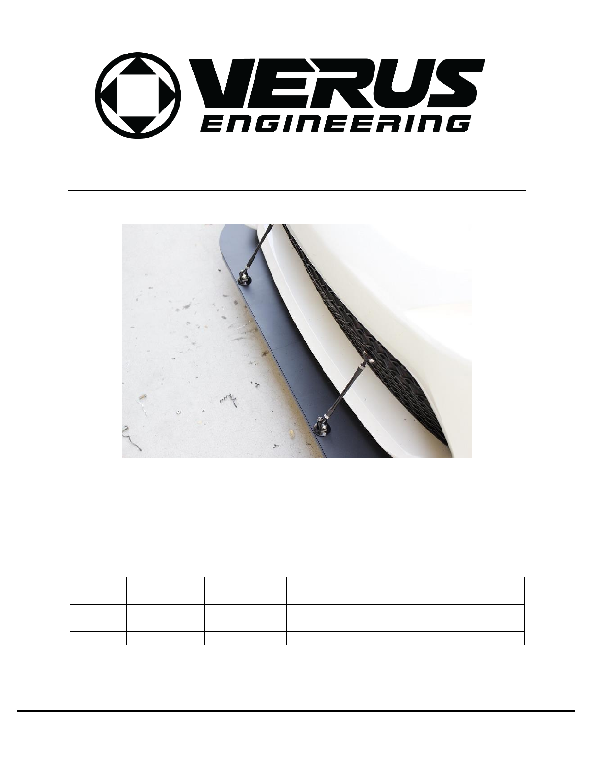
ZC6 / ZN6 Two Piece Front Splitter –Install Manual
1. Introduction
1.1. Overview: Detailed instructions on installing the two piece front splitter with supplied
support rod kit for the ZN6 ZC6 chassis.
1.2. Difficulty: Beginner to Moderate
1.3. Time Required: 2.5-4 hours
1.4. Tools Needed:
1.4.1.Splitter Install
1.4.1.1. Jack and Jack Stands
1.4.1.2. Screwdriver
1.4.1.3. 10mm Socket
1.4.1.4. 4mm Allen Wrench
1.4.1.5. 5mm Allen Wrench
1.4.1.6. 9/16” wrench
1.4.1.7. Center Punch
1.4.1.8. 1/8” or starter drill bit
1.4.1.9. 1/4” drill bit
1.4.1.10. Drill
1.4.1.11. Spray paint/touch up paint
1.5. Splitter Components
1.5.1. Two Splitter Halves
1.5.2. Hardware Bag
1.5.2.1. (2) M6 x 1.0 Button Head Cap Screw (BHCS) x 16mm Long
1.5.2.2. (12) M6 x 1.0 BHCS x 30mm Long
1.5.2.3. (2) M6 Aluminum Spacers
1.5.2.4. (14) M6 x 38mm Diameter Fender Washers
1.5.2.5. (10) M6 x 1.0 Plastic Rivets
1.5.2.6. (8) 3/8” ID Rivet Nut Backing Washers
1.5.2.7. (6) M6 x 1.0 BHCS x 25mm Long
1.5.2.8. (8) M6 x 18mm Diameter Washer
1.5.2.9. (6) M6 x 1.0 Flanged Nut
1.5.2.10. (1) M6 Install Tool
1.5.2.11. (2) M6 x 1.0 Socket Head Cap Screw (SHCS) x 35mm Long Bolt
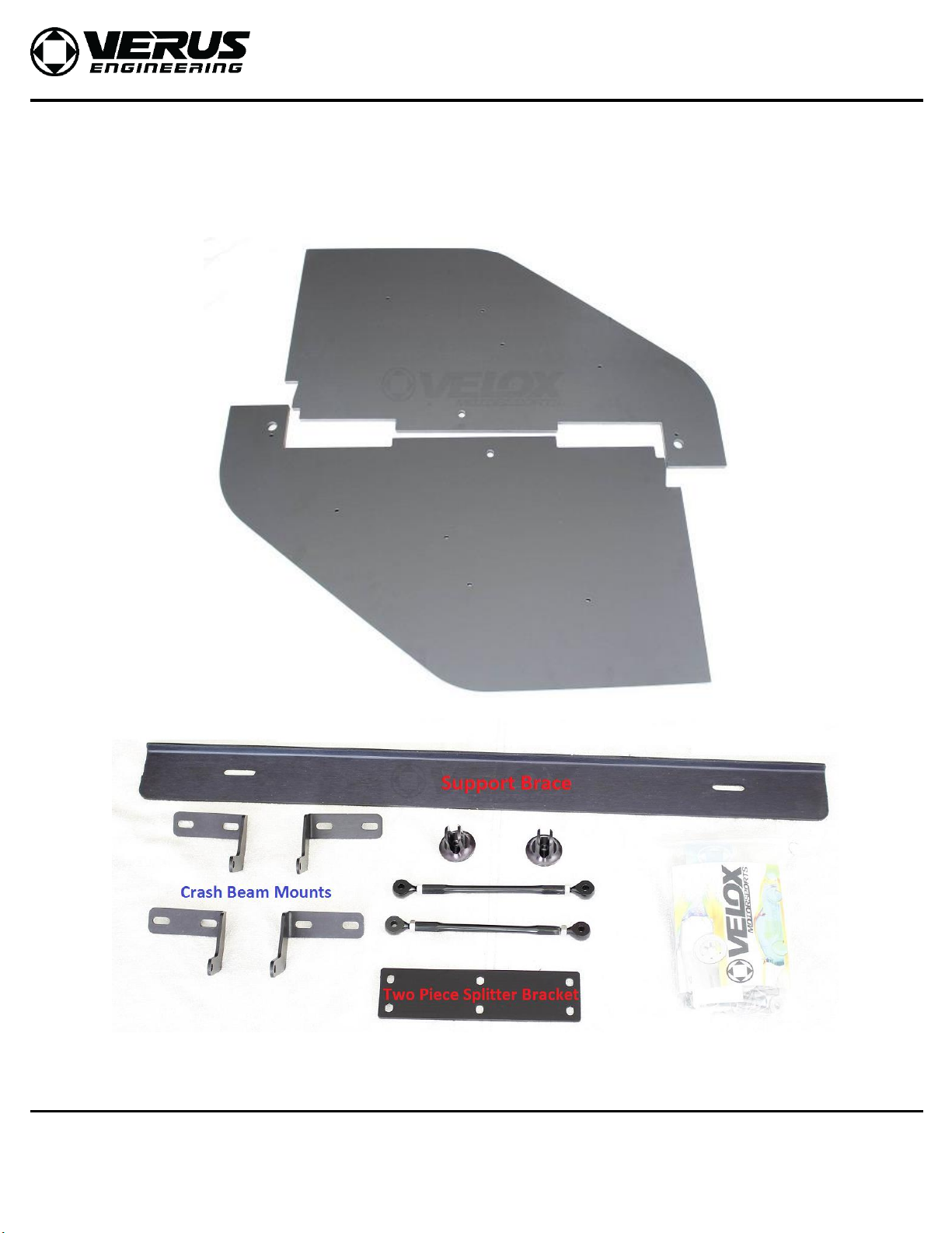
1.6. Splitter Rod Components
1.6.1. (2) Splitter Rods
1.6.2. (2) Billet Aluminum Clevis Mounts
1.6.3. (4) Crash Beam Mounts
1.6.4. (1) Support Brace
1.6.5. (1) Two Piece Splitter Bracket
1.6.6. Hardware Bags
1.6.6.1. (8) M6 x 18mm Diameter Washer
1.6.6.2. (12) M6 x 1.0 Flanged Nut