manuals.online logo
Brands
  1. Home
  2. •
  3. Brands
  4. •
  5. Verus Engineering
  6. •
  7. Automobile Accessories
  8. •
  9. Verus Engineering ZN6 Manual

Verus Engineering ZN6 Manual

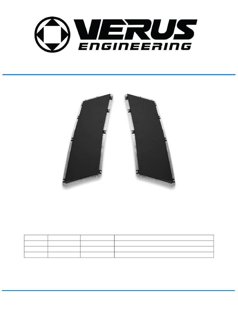
ZN6 / ZC6 Adjustable Carbon Thermoplastic
Front Splitter
Install Manual
Author: Eric Hazen
Release Date: 2016/11/08
Approvals:E. Hazen, P. Lucas
Document Revisions
Rev
Date
Author
Description
01
2016/11/08
E.Hazen
Initial release of install manual.
02
2017/08/08
P. Lucas
Company name change from Velox to Verus
03
2021/07/01
C. Warner
Hardware Update
Confidential: Property of Verus Engineering. Not for Distribution outside intended recipient list.
Verus Engineering
sales@verus-engineering.com
2 3/6/2016
Author: Eric Hazen
Date: 2016/11/09
Recipients: Public
ENGINEERING | NORTH AMERICA
REVISION: R01
Confidential: Property of Verus Engineering. Not for Distribution outside intended recipient list.
Verus Engineering
sales@verus-engineering.com
ZN6/ZC6 Chassis Adjustable Carbon Thermoplastic Front Splitter
CONTENTS
1. Introduction ....................................................................................................................................... <3>
1.1. Overview .................................................................................................................................... <3>
1.2. Difficult....................................................................................................................................... <3>
1.3. Time Required............................................................................................................................ <3>
1.4. Tools Needed ............................................................................................................................. <3>
1.5. Splitter Components...............................................................................................................<3-4>
2. Front Splitter Install......................................................................................................................<4-15>
3 3/6/2016
Author: Eric Hazen
Date: 2016/11/09
Recipients: Public
ENGINEERING | NORTH AMERICA
REVISION: R01
Confidential: Property of Verus Engineering. Not for Distribution outside intended recipient list.
Verus Engineering
sales@verus-engineering.com
ZN6/ZC6 Chassis Adjustable Carbon Thermoplastic Front Splitter
1. Introduction
1.1. Overview: Detailed instructions on installing the adjustable, carbon thermoplastic, splitter
for the ZN6/ZC6 chassis.
1.2. Difficulty: Moderate
1.3. Time Required: 4 hours
1.4. Tools Needed:
1.4.1.Splitter Install
1.4.1.1. Jack and Jack Stands
1.4.1.2. Screwdriver
1.4.1.3. 10mm Socket
1.4.1.4. Ratchet
1.4.1.5. 5/32 Allen Wrench
1.4.1.6. 5/64 Allen Wrench
1.4.1.7. 5/16 Thin wall socket
1.4.1.8. 3/8 wrench
1.4.1.9. 7/16 wrench
1.4.1.10. Drill
1.4.1.11. Tape Measure
1.4.1.12. Center Punch
1.4.1.13. Starter Drill Bit or Pilot Sized Drill bit (1/8”)
1.4.1.14. 1/4” Drill Bit
1.4.1.15. 2” hole saw
1.4.1.16. Touch up paint (optional)
1.4.1.17. Level
1.5. Splitter Components
1.5.1. Splitter
1.5.2. (2) Two Inch Splitter Extension
1.5.3. (2) One Inch Splitter Extension
1.5.4. (7) Splitter Support Rod Assembly
1.5.5. (6) Splitter Support Rod Extender
1.5.6. (10) Support Rod Clevis
1.5.7. (2) Left Core Support Bracket
1.5.8. (2) Right Core Support Bracket
1.5.9. (1) Hardware Bag
1.5.9.1. (12) M6 18mm Washer
1.5.9.2. (24) M6 Serrated Nut
1.5.9.3. (12) M6 12mm Washer
1.5.9.4. (18) M6 25mm BHCS
1.5.9.5. (16) M6 16mm BHCS
4 3/6/2016
Author: Eric Hazen
Date: 2016/11/09
Recipients: Public
ENGINEERING | NORTH AMERICA
REVISION: R01
Confidential: Property of Verus Engineering. Not for Distribution outside intended recipient list.
Verus Engineering
sales@verus-engineering.com
ZN6/ZC6 Chassis Adjustable Carbon Thermoplastic Front Splitter
1.5.9.6. (10) 1/4" x 1.50”Fender Washer
1.5.9.7. (2) M6 60mm BHCS
1.5.9.8. (8) 6-32 Nyloc Nut
1.5.9.9. (8) 6-32 0.38”FHCS
1.5.9.10. (4) M6 5mm Nylon Spacer
1.5.9.11. (4) M6 10mm Nylon Spacer
2. Front Splitter Installation
2.1. Verus is not responsible for damage to you or your vehicle by following this manual and/or
installing Verus Engineering products
5 3/6/2016
Author: Eric Hazen
Date: 2016/11/09
Recipients: Public
ENGINEERING | NORTH AMERICA
REVISION: R01
Confidential: Property of Verus Engineering. Not for Distribution outside intended recipient list.
Verus Engineering
sales@verus-engineering.com
ZN6/ZC6 Chassis Adjustable Carbon Thermoplastic Front Splitter
2.2. Due to the mounting of this splitter, at certain points during the install, you may have to
interpret your own specific mounting on the splitter.
2.3. We begin by jacking the car up on a level surface. Use of the e-brake and/or wheel chocks is
suggested.
2.4. Secure the car with two jack stands with enough room to access all the area under the front
bumper.
2.5. Remove the plastic panel located in-between the radiator and the front bumper. There will
be six push pins (shown in red below) and three 10mm bolts to remove (shown in yellow
below).
2.6. We will need to fully remove the front bumper for this install. To remove the front bumper,
remove the strip of 10mm bolts and plastic push pins across the top of the front bumper.
2.7. On each side of the car in the wheel wells, we’ll want to remove the (4) plastic screw pins.
Three are located on the bottom portion of the wheel well (shown below) and the last one is
near the side marker.
6 3/6/2016
Author: Eric Hazen
Date: 2016/11/09
Recipients: Public
ENGINEERING | NORTH AMERICA
REVISION: R01
Confidential: Property of Verus Engineering. Not for Distribution outside intended recipient list.
Verus Engineering
sales@verus-engineering.com
ZN6/ZC6 Chassis Adjustable Carbon Thermoplastic Front Splitter
2.8. The turn signal has to be removed to expose the final plastic push pin and then the front
bumper will come off. There is a metal tab that needs to be push towards the *front* of the
car. The arrow in the picture shows this well. We use a flat head screwdriver to push this
forward and then gently pried the signal away from the car.
2.9. The final push pin is circled here. Remove this with a flat head screw driver.
7 3/6/2016
Author: Eric Hazen
Date: 2016/11/09
Recipients: Public
ENGINEERING | NORTH AMERICA
REVISION: R01
Confidential: Property of Verus Engineering. Not for Distribution outside intended recipient list.
Verus Engineering
sales@verus-engineering.com
ZN6/ZC6 Chassis Adjustable Carbon Thermoplastic Front Splitter
2.10. Gently pry around the front bumper to remove it completely. Pull outward and
forward. If it does not come easily, ensure all bolts/push pins/etc are completely removed!
2.11. We are to the point where we can begin installing the actual splitter components! But
first, we need to decide how far out from the front bumper you want the splitter to sit.
2.12. For an approximately 2” front splitter, you will not add any extensions, for the 3”, you’ll
add the 1” extension, for 4” you’ll add the 2” extension, and finally for 5”, you’ll add the 1”
and 2” extensions.
2.13. Once you decide which length you’re interested in, it is time to install these extensions.
Using a 5/64” allen wrench and a 5/16” thin wall socket, we can install the 6-32 hardware as
shown below. We went with the 3” length currently, which is what you’ll see below. These
fasteners just need to be snug, as the nyloc should not back off.
8 3/6/2016
Author: Eric Hazen
Date: 2016/11/09
Recipients: Public
ENGINEERING | NORTH AMERICA
REVISION: R01
Confidential: Property of Verus Engineering. Not for Distribution outside intended recipient list.
Verus Engineering
sales@verus-engineering.com
ZN6/ZC6 Chassis Adjustable Carbon Thermoplastic Front Splitter
2.14. Starting with the core support front mounts, we can follow the same install procedure
as our race upgrade. This starts with drilling the front crash beam. You will notice that there
are raised portions of the crash beam and then portions with spot welds on it. You will want
to drill the raised portions as drilling through a spot weld can get bad quickly. The splitter
supports were designed around an 18.50” spread, which leaves *6 raised* sections between
the brackets. Center punch the next 4 raised portions, using the brackets to ensure that you
can bolt them on the crash beam in the location necessary for a proper install with the grill.
9 3/6/2016
Author: Eric Hazen
Date: 2016/11/09
Recipients: Public
ENGINEERING | NORTH AMERICA
REVISION: R01
Confidential: Property of Verus Engineering. Not for Distribution outside intended recipient list.
Verus Engineering
sales@verus-engineering.com
ZN6/ZC6 Chassis Adjustable Carbon Thermoplastic Front Splitter
2.15. It is recommended to use a starter drill bit next (top left of picture) as these can greatly
help cutting through sheet metal and ensuring that the drill is going through the material
straight.
2.16. Using the 1/4" drill bit, drill through both parts of the sheet metal. Vacuum out all of the
metal shavings you can. It is recommended to spray the holes with spray paint or touch up
paint (at the very least) and underbody rust resistant if you have some. This ensures that the
crash beam will not rust for years to come.
10 3/6/2016
Author: Eric Hazen
Date: 2016/11/09
Recipients: Public
ENGINEERING | NORTH AMERICA
REVISION: R01
Confidential: Property of Verus Engineering. Not for Distribution outside intended recipient list.
Verus Engineering
sales@verus-engineering.com
ZN6/ZC6 Chassis Adjustable Carbon Thermoplastic Front Splitter
1.1. Ensure that the brackets will fit and that they can slide together till there is a 10mmgap
between the two mounting holes for the splitter tie rods. Do this by using the (8) M6 x 1.0 x
16mm long BHCS, (8) M6 x 18mm, and the (8) M6 x 1.0 flanged nuts. You do not need to
tighten these down, just enough to know if the brackets will work once the bumper is put back
on. Once you ensure the holes were drilled properly, remove the brackets and reinstall the
bumper in reverse order
1.2. For the rear outside mounting locations, we need to lengthen the support rods, which are
what the extension units are for. Fully tighten (3) of these onto the support rod. The
support rod has a left hand and a right hand side thread, these go on the right hand thread
side. Note: When tightening these into one another, use lubricant and/or anti-sieze. If
you notice resistance, back out the unit, ensure the threads are clean, and try again.
2.17. Install this lengthened support rod with a clevis in the location shown below. Use a
25mm BHCS, 12mm washer, and a serrated nuts to fasten the support rod to the clevis. Use
a 16mm long bolt, 18mm washer, and the M6 flanged nut to tighten the clevis onto the car.
11 3/6/2016
Author: Eric Hazen
Date: 2016/11/09
Recipients: Public
ENGINEERING | NORTH AMERICA
REVISION: R01
Confidential: Property of Verus Engineering. Not for Distribution outside intended recipient list.
Verus Engineering
sales@verus-engineering.com
ZN6/ZC6 Chassis Adjustable Carbon Thermoplastic Front Splitter
1.3. Install the lengthened support rod on the other side as well.
1.4. The last two location are the middle two points. These are not necessary light use; but for
heavy use we recommend adding these to further strengthen the splitter’s support system.
1.5. To install these middle two locations, you’ll need to drill holes into the core support on the
bottom side. The clevis will go on the bottom side and a BHCS and washer will tighten the
clevis from the top. You will need to ensure that the location you choose will allow the
support rod to be long enough to fasten to the splitter yet.
1.6. We recommend installing the splitter at this time to make a few more holes, so install the
front support rods to the brackets on the core support at this time.
12 3/6/2016
Author: Eric Hazen
Date: 2016/11/09
Recipients: Public
ENGINEERING | NORTH AMERICA
REVISION: R01
Confidential: Property of Verus Engineering. Not for Distribution outside intended recipient list.
Verus Engineering
sales@verus-engineering.com
ZN6/ZC6 Chassis Adjustable Carbon Thermoplastic Front Splitter
1.7. Temporarily install the splitter via the rear two points and the front most two points. The
rear two points receive the 60mm long BHCS, large fender washer, spacers, and the serrated
nut on top as shown below. We recommend using the outer hole locations.
1.8. The holes are marked below for location on how far forward the front splitter will sit.
1.9. Temporarily install the front two locations as well.
1.10. If you plan to use the middle two locations with the plastic piece that is under the
radiator, which we recommend, you’ll need to punch two holes out of this. Using a hole
saw, make two cuts in the plastic based off the hole location on the splitter. This is shown
below.
13 3/6/2016
Author: Eric Hazen
Date: 2016/11/09
Recipients: Public
ENGINEERING | NORTH AMERICA
REVISION: R01
Confidential: Property of Verus Engineering. Not for Distribution outside intended recipient list.
Verus Engineering
sales@verus-engineering.com
ZN6/ZC6 Chassis Adjustable Carbon Thermoplastic Front Splitter
1.11. Moving to the rear outside two locations, we’ll need to cut holes in the fender liner so
that we can fasten the splitter to the support rod here.
1.12. With the splitter off, this cut out looks like this from below.
14 3/6/2016
Author: Eric Hazen
Date: 2016/11/09
Recipients: Public
ENGINEERING | NORTH AMERICA
REVISION: R01
Confidential: Property of Verus Engineering. Not for Distribution outside intended recipient list.
Verus Engineering
sales@verus-engineering.com
ZN6/ZC6 Chassis Adjustable Carbon Thermoplastic Front Splitter
1.13. With the bumper off still, fasten the splitter to all (6) support rods and using the level,
level the splitter to the best of your abilities as the height it will be installed at. Lengthen
the support to move the splitter down, shorten the support to bring it upward.
1.14. Reinstall the bumper and ensure fitment of the splitter to the bumper looks and fits
well. Adjust as necessary and then remove the bumper for step 2.33.
1.15. Depending on how far forward you install the splitter, the bumper may need a bit of
clearance for the clevis to bolt to the splitter. This is shown below.
1.16. When fitment is to your liking, tighten all the support rod locking nuts and tighten the
rod ends to the clevis. Remember, one side is right hand thread, the other is left hand
thread.
1.17. Once all the support rods are fully tightened, we can install the bumper and splitter for
the last time.
1.18. Reinstall the bumper in reverse order and bolt the splitter onto the support rods. Utilize
25mm BHCS and the 1/4" fender washers.
1.19. These bolts only need tightened to roughly 8-14 ft-lbs, just past snug.
15 3/6/2016
Author: Eric Hazen
Date: 2016/11/09
Recipients: Public
ENGINEERING | NORTH AMERICA
REVISION: R01
Confidential: Property of Verus Engineering. Not for Distribution outside intended recipient list.
Verus Engineering
sales@verus-engineering.com
ZN6/ZC6 Chassis Adjustable Carbon Thermoplastic Front Splitter
1.20. Congratulations, you’ve successfully installed the Velox adjustable carbon thermoplastic
splitter! Enjoy the increase in front end downforce. Please let Velox know of any feedback,
concerns, and questions via our e-mail, [email protected]m.

Other manuals for ZN6

2

This manual suits for next models

1

Other Verus Engineering Automobile Accessories manuals
Verus Engineering Wing Riser 991 GT3 Manual

Verus Engineering

Verus Engineering Wing Riser 991 GT3 Manual

Verus Engineering A0105A Manual

Verus Engineering

Verus Engineering A0105A Manual

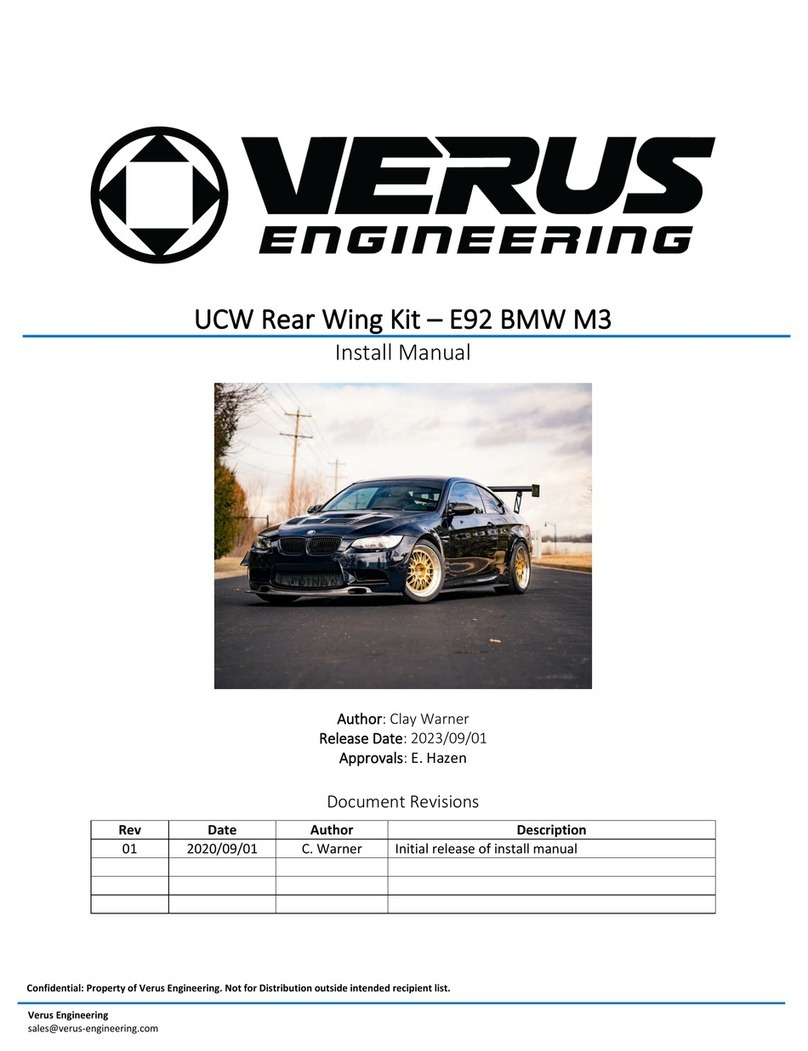
Verus Engineering UCW Rear Wing Kit Manual

Verus Engineering

Verus Engineering UCW Rear Wing Kit Manual

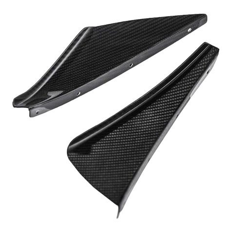
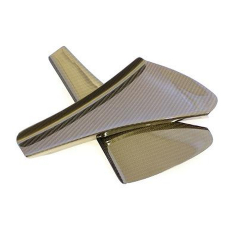
Verus Engineering Dive Plane Manual

Verus Engineering

Verus Engineering Dive Plane Manual
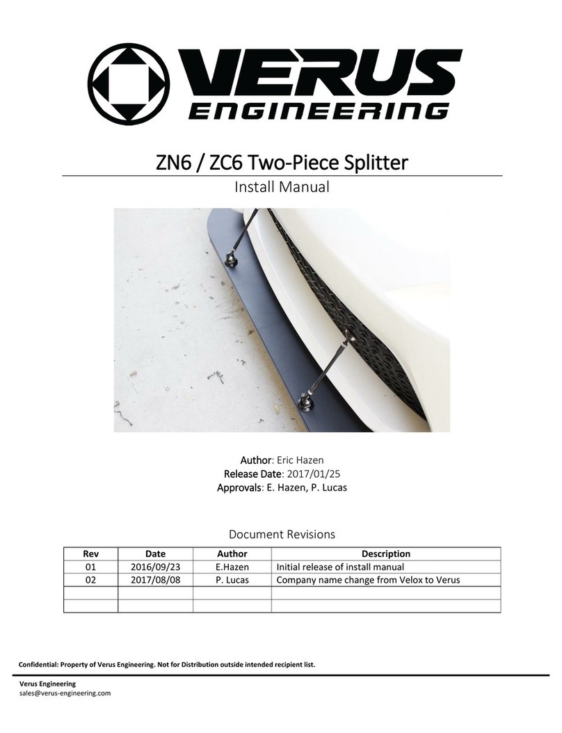
Verus Engineering A0158A User manual

Verus Engineering

Verus Engineering A0158A User manual

Verus Engineering ZN6 Manual

Verus Engineering

Verus Engineering ZN6 Manual

Verus Engineering ZN6 Manual

Verus Engineering

Verus Engineering ZN6 Manual
Popular Automobile Accessories manuals by other brands

EXTOL PREMIUM 8891510 user manual

EXTOL PREMIUM

EXTOL PREMIUM 8891510 user manual

Techart 097.460.350.009 Mounting instructions

Techart

Techart 097.460.350.009 Mounting instructions

B-PWR SG5FB-HD installation guide

B-PWR

B-PWR SG5FB-HD installation guide

Sony X-7BT operating instructions

Sony

Sony X-7BT operating instructions

Denso KRISTAL user manual

Denso

Denso KRISTAL user manual

Progress Equal-i-zer 90-00-0600 owner's manual

Progress

Progress Equal-i-zer 90-00-0600 owner's manual

3Rtablet VT-7 GE user manual

3Rtablet

3Rtablet VT-7 GE user manual

Warn 79403 installation instructions

Warn

Warn 79403 installation instructions

Rogers Smart Drive Start guide

Rogers

Rogers Smart Drive Start guide

Steinhof H-050 FITTING AND OPERATION MANUAL

Steinhof

Steinhof H-050 FITTING AND OPERATION MANUAL

CrimeStopper CS-9601PI Wiring diagram

CrimeStopper

CrimeStopper CS-9601PI Wiring diagram

KW automotive 685 10 456 installation instructions

KW automotive

KW automotive 685 10 456 installation instructions

STO N SHO SNS 278 manual

STO N SHO

STO N SHO SNS 278 manual

Hunter Quick Check Drive Operation instructions

Hunter

Hunter Quick Check Drive Operation instructions

Classic Accessories PolyPRO 3 instructions

Classic Accessories

Classic Accessories PolyPRO 3 instructions

Weh TK16 H2 operating instructions

Weh

Weh TK16 H2 operating instructions

BOSSTOW A0385 Fitting instructions

BOSSTOW

BOSSTOW A0385 Fitting instructions

Federal Signal Corporation CommCenter D1 Series Installation and service instructions

Federal Signal Corporation

Federal Signal Corporation CommCenter D1 Series Installation and service instructions

manuals.online logo
manuals.online logoBrands
  • About & Mission
  • Contact us
  • Privacy Policy
  • Terms and Conditions

Copyright 2025 Manuals.Online. All Rights Reserved.