manuals.online logo
Brands
  1. Home
  2. •
  3. Brands
  4. •
  5. Vestil
  6. •
  7. Ladder
  8. •
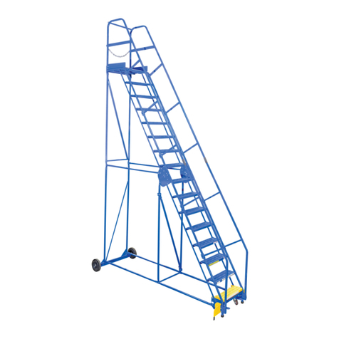
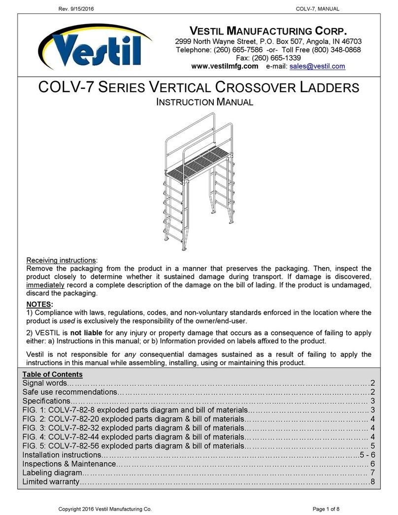
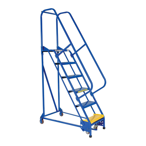
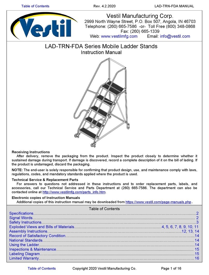
  9. Vestil LAD Series User manual

Vestil LAD Series User manual

Other manuals for LAD Series

1

This manual suits for next models

16

Other Vestil Ladder manuals

Vestil DKL Series User manual

Vestil

Vestil DKL Series User manual

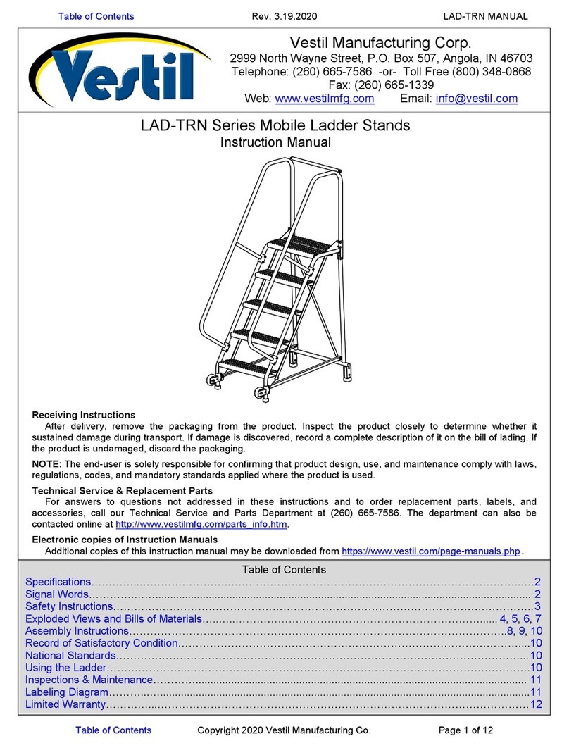
Vestil LAD-TRN Series User manual

Vestil

Vestil LAD-TRN Series User manual

Vestil Tip-N-Roll LAD-TRN-FDA Series User manual

Vestil

Vestil Tip-N-Roll LAD-TRN-FDA Series User manual

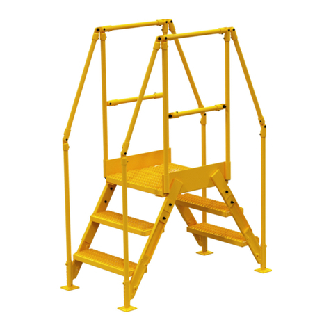
Vestil COL-3-26-44 User manual

Vestil

Vestil COL-3-26-44 User manual

Vestil COL-3-26-23 User manual

Vestil

Vestil COL-3-26-23 User manual

Vestil COL-4-36-33 User manual

Vestil

Vestil COL-4-36-33 User manual

Vestil VST-4-Y User manual

Vestil

Vestil VST-4-Y User manual

Vestil LAD-PW-18-2-P User manual

Vestil

Vestil LAD-PW-18-2-P User manual

Vestil LAD-FM-PSO User manual

Vestil

Vestil LAD-FM-PSO User manual

Vestil COL-4-36-23 User manual

Vestil

Vestil COL-4-36-23 User manual

Vestil COLV-7 Series User manual

Vestil

Vestil COLV-7 Series User manual

Vestil COL-4-36-14 User manual

Vestil

Vestil COL-4-36-14 User manual

Vestil PWPS User manual

Vestil

Vestil PWPS User manual

Vestil COL-6-56-23 User manual

Vestil

Vestil COL-6-56-23 User manual

Vestil LAD Series User manual

Vestil

Vestil LAD Series User manual

Vestil SPS3 Series User manual

Vestil

Vestil SPS3 Series User manual

Vestil LAD-RAF Series User manual

Vestil

Vestil LAD-RAF Series User manual

Vestil LAD-MM Series User manual

Vestil

Vestil LAD-MM Series User manual

Vestil COL HDG Series User manual

Vestil

Vestil COL HDG Series User manual

Vestil COL-3-26-14 User manual

Vestil

Vestil COL-3-26-14 User manual

Vestil LAD-FM-60 User manual

Vestil

Vestil LAD-FM-60 User manual

Vestil LAD-TRS Series User manual

Vestil

Vestil LAD-TRS Series User manual

Vestil LAD-EZ Series User manual

Vestil

Vestil LAD-EZ Series User manual

Vestil ATS-6-56 User manual

Vestil

Vestil ATS-6-56 User manual

Popular Ladder manuals by other brands

smirthwaite Walking Ladders Instructions for use

smirthwaite

smirthwaite Walking Ladders Instructions for use

Batavia GIRAFFE AIR operating instructions

Batavia

Batavia GIRAFFE AIR operating instructions

wibe TMR Mounting instruction

wibe

wibe TMR Mounting instruction

BESSLER 20 manual

BESSLER

BESSLER 20 manual

Millennium L-220-SL instruction manual

Millennium

Millennium L-220-SL instruction manual

Louisville AA2210 installation instructions

Louisville

Louisville AA2210 installation instructions

TUBESCA-COMABI 02271 105 à 115 operating manual

TUBESCA-COMABI

TUBESCA-COMABI 02271 105 à 115 operating manual

ADVANCED SIMRACING ASR6 Assembly guide

ADVANCED SIMRACING

ADVANCED SIMRACING ASR6 Assembly guide

KRAUSE 1103 Series user manual

KRAUSE

KRAUSE 1103 Series user manual

Tractel skysafe Assembly and operating manual

Tractel

Tractel skysafe Assembly and operating manual

AFIX FAST FIX Assembly guide

AFIX

AFIX FAST FIX Assembly guide

Wenger Fixed Height Stairway 2-Step Assembly instructions

Wenger

Wenger Fixed Height Stairway 2-Step Assembly instructions

KRAUSE 1212 user manual

KRAUSE

KRAUSE 1212 user manual

FACAL Euro Stilo Use and maintenance handbook

FACAL

FACAL Euro Stilo Use and maintenance handbook

Malta Dynamics R0001 quick start guide

Malta Dynamics

Malta Dynamics R0001 quick start guide

Sutphen SL75 Operation manual

Sutphen

Sutphen SL75 Operation manual

Sapa REDD Team Dura-Grip OSHA Assembly

Sapa

Sapa REDD Team Dura-Grip OSHA Assembly

RGC PRO400 instructions

RGC

RGC PRO400 instructions

manuals.online logo
manuals.online logoBrands
  • About & Mission
  • Contact us
  • Privacy Policy
  • Terms and Conditions

Copyright 2025 Manuals.Online. All Rights Reserved.

Table of Contents Rev. 12/8/2020 LAD (13-16 STEPS), MANUAL
Table of Contents Copyright 2019 Vestil Manufacturing Co. Page 1 of 19
LAD-series Portable Warehouse Ladders, 13-16 Steps
Instruction Manual
Receiving Instructions
After delivery, remove the packaging from the product. Inspect the product closely to determine whether it
sustained damage during transport. If damage is discovered, record a complete description of it on the bill of lading. If
the product is undamaged, discard the packaging.
NOTE: The end-user is solely responsible for confirming that product design, use, and maintenance comply with laws,
regulations, codes, and mandatory standards applied where the product is used.
Technical Service & Replacement Parts
For answers to questions not addressed in these instructions and to order replacement parts, labels, and
accessories, call our Technical Service and Parts Department at (260) 665-7586. The department can also be
contacted online at http://www.vestilmfg.com/parts_info.htm.
Electronic copies of Instruction Manuals
Additional copies of this instruction manual may be downloaded from https://www.vestil.com/page-manuals.php.
Table of Contents
Signal Words……………………………………………………………………………………………………………………….2
Safety Instructions……...……………………………………………………………..………………………………………….. 2
Specifications……………..…………………………………………………………………………………………………..……3
FIGURES 1, 2, 3, 4, 5, & 6: Exploded Parts Diagrams and Bills of Materials………....………………..……4, 5, 6, 7, 8, 9
Installing Casters………………………………………………………………………………………………………………… 10
Assembling the Ladder..……………………………………………………….……………………………11, 12, 13, 14, & 15
Record of Satisfactory Condition………………………………………………………………………………………………. 16
National Standards……………………………………………………………………………………………………………….16
Using the Ladder………………………………………………………………………………………..……………..………… 16
Inspections & Maintenance………………………………………………………………………………………………...16 - 17
Labeling Diagram………………………………………………………..………………………………………………………. 18
Limited Warranty……………………………………………………………………………………………………………..……19
Vestil Manufacturing Corp.
2999 North Wayne Street, P.O. Box 507, Angola, IN 46703
Telephone: (260) 665-7586 -or-Toll Free (800) 348-0868
Fax: (260) 665-1339
Website: www.vestilmfg.com e-Mail:
HU
[email protected]
U
Table of Contents Rev. 12/8/2020 LAD (13-16 STEPS), MANUAL
Table of Contents Copyright 2019 Vestil Manufacturing Co. Page 2 of 19
SIGNAL WORDS
This manual uses SIGNAL WORDS to indicate the likelihood of personal injuries, as well as the probable
seriousness of those injuries, if the product is misused in the ways described. Other signal words call attention to uses
of the product likely cause property damage. The signal words used appear below along with the meaning of each
word:
Identifies a hazardous situation which, if not avoided, WILL result in DEATH or SERIOUS
INJURY. Use of this signal word is limited to the most extreme situations.
Identifies a hazardous situation which, if not avoided, COULD result in DEATH or
SERIOUS INJURY.
Identifies practices likely to result in product/property damage, such as operation that
might damage the crane.
SAFETY INSTRUCTIONS
Vestil strives to identify foreseeable hazards associated with the use of its products. However, no manual can
address every conceivable risk. The most effective way to avoid injury is to exercise sound judgment when
assembling, using, inspecting, and maintaining this ladder. Keep a copy of this manual with the ladder at all times.
For example, put the copy inside a plastic pouch and attach the pouch to the frame. Anyone who uses this ladder
must be made aware that a copy of the manual is available and where to find it.
Improper or careless use could result in serious personal injuries or death.
•Read and understand the entire manual before assembling, using, inspecting, or servicing the ladder.
•DO NOT use this ladder unless you are in good health. NEVER use the ladder while under the influence of
alcohol or drugs, including prescription medication that affects balance, perception, or judgment.
•DO NOT exceed the capacity/rated load. The total weight applied to the ladder (weight of the user plus tools, etc.)
must not be greater than the capacity. The capacity is provided on label 287. See Labeling Diagram on p. 18.
•Wear appropriate footwear. DO NOT wear high-heeled shoes or footwear with smooth soles. DO NOT use the
ladder on uneven, sloped, or unstable surfaces. ONLY use the ladder on even, level, improved surfaces
(concrete or asphalt).
•Make sure that you will not contact overhead objects with either your body or with the ladder during use.
•Avoid electrical shock! Take precautions to prevent any contact, or possible contact, with an energized, insulated
conductor (electrical line).
•Remove foreign matter, e.g. mud, from your shoes before walking on the ladder. Only wear slip-resistant shoes.
•Only stand on the steps. DO NOT climb on the railing. DO NOT slide on the railing.
•DO NOT access, or egress from, any step from another elevated surface unless the ladder is positively secured
against movement.
•ALWAYS face the steps and use the handrails while ascending or descending the ladder.
•DO NOT increase the height of a step by standing on other objects placed on the ladder.
•Inspect the ladder as described in Inspections & Maintenance on p. 16-17. DO NOT use the ladder unless it is in
Satisfactory Condition. ONLY use manufacturer-approved replacement parts when repairs are necessary.
•DO NOT use the ladder if either square cap (99-024-027) is worn. See applicable Exploded View on p. 4-9. Caps
should prevent the ladder from sliding. Replace worn or damaged caps before using the ladder.
•ONLY use the ladder to access elevated working positions. DO NOT use the ladder for any other purpose. DO NOT
store materials and/or equipment on the steps. Always unload the ladder before leaving it unattended.
•DO NOT position an occupied ladder in front of a door unless that door is secured in an open position, is locked, is
attended, or is barricaded.
•DO NOT lean, or reach, over the side rails or handrails of the ladder. Position the ladder as close to the work as
possible. Reposition the ladder to prevent overreaching. Overreaching could cause instability and result in a fall.
•Avoid sudden shifts while on the ladder.
•DO NOT push, pull, or lean on the handrails.
•DO NOT skip steps. Climb the ladder one step at a time.
•DO NOT attempt to move the ladder while someone is using it. The ladder must be unoccupied before it is moved.
•DO NOT use the ladder to transport people or objects. DO NOT ride on the ladder.
•DO NOT remove or obscure any label. Each label must be readable, undamaged, and present in the appropriate
location. See Labeling Diagram on p. 18.
•DO NOT modify this ladder! Unauthorized modifications automatically void the Limited Warranty (p. 19)and might
make the ladder unsafe to use.
•While assembling this ladder, confirm that only locking fasteners are provided, i.e. only locking nuts. Contact
Technical Service (p. 1) if you find non-locking nuts. Only lock nuts should be used. However, lock nuts can only
safely be used once. Discard the used lock nut and install a new lock nut after unfastening a connection.
Table of Contents Rev. 12/8/2020 LAD (13-16 STEPS), MANUAL
Table of Contents Copyright 2019 Vestil Manufacturing Co. Page 3 of 19
NOTE: If your model is not included on the webpage, or if you cannot access and/or print the document, contact
the Technical Service Dept. Contact information is provided on the front page of this manual.
SPECIFICATIONS
Documents that provide specifications for LAD series mobile ladder stands are available online to anyone who
visits the Vestil website. Specifications include dimensions, net weight, and capacity information. Acquire the
appropriate specifications document by opening this webpage: https://www.vestil.com/product.php?FID=607. Click
the “Specifications” tab. Scroll the page to the entry for the product you purchased. Click the button in the “PDF”
column that looks like a pencil inside a blue-bordered box. A PDF file will open. This file is the specifications
document. Print a copy of the document as soon as your ladder is delivered and keep it with your copy of this
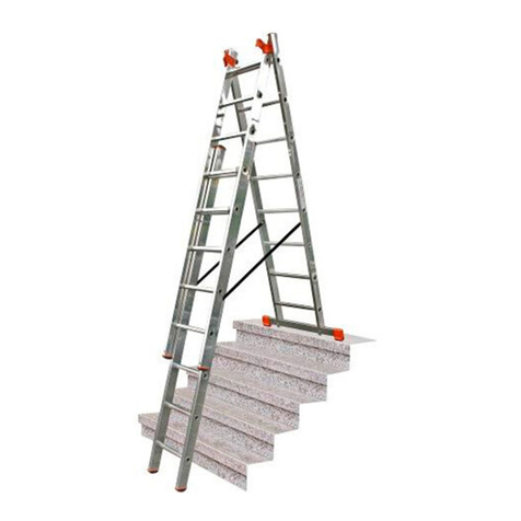
manual. If you encounter difficulties while trying to obtain a copy of the specifications document, contact Technical
Service. Contact information is provided on the cover page of this manual.
The following is an exemplar specifications document. In this case, it shows a LAD-13-14-G.
Table of Contents Rev. 12/8/2020 LAD (13-16 STEPS), MANUAL
Table of Contents Copyright 2019 Vestil Manufacturing Co. Page 4 of 19
FIG. 1: Foot Lock Mechanism Exploded View and Bill of Materials
Part no. Description Quantity
11055 5/16in. – 18 x 1in. HHCS #2 zinc-plated bolt 2
11061 5/16in. – 18 x 2in. HHCS #2 zinc-plated bolt 4
11105 3/8in. – 16 x 1in. hex head bolt 2
26329 3/8in. shoulder x 3/4in. x 5/16in. – 18 2
33006 5/16in. USS zinc-plated flat washer 2
33456 11/8in. I.D. 10 gauge machine bushing 2
36106 3/8in. – 16 zinc-plated hex nut 2
37024 3/8in. Nylock insert nut 4
65127 3/16in. x 2in. zinc-plated cotter pin 2
20-027-005 Roller guide 4
28-146-003 Spring 2
44-514-354
Weldment, frame, caster pivot foot lock “caster
bracket”
1
Table of Contents Rev. 12/8/2020 LAD (13-16 STEPS), MANUAL
Table of Contents Copyright 2019 Vestil Manufacturing Co. Page 5 of 19
Item
Part no.
Description
Quantity
1
44-647-256
44-647-255
44-647-258
44-647-257
Weldment, 58°, upper (8) steps:
LAD-13-14-G
LAD-13-14-P
LAD-13-21-G
LAD-13-21-P
1
1
1
1
2
44-647-264
44-647-263
Weldment, lower (5) steps:
LAD-13-14-G & LAD-13-21-G
LAD-13-14-P & LAD-13-21-P
1
1
3
44-514-314
Weldment, frame, back platform
2
4
44-514-354
Weldment, frame, caster pivot foot lock
1
5
44-514-399
Assembly, frame, outrigger, right
1
6
44-514-400
Assembly, frame, outrigger, left
1
7
44-514-401
Weldment, support frame, upper 8 steps
1
8
44-514-402
Weldment, support frame, lower 13 steps
1
9
44-524-147
44-524-148
Weldment, handrail, 58° climb, top:
LAD-13-14-G & LAD-13-14-P
LAD-13-21-G & LAD-13-21-P
2
2
10
44-524-151
Weldment, handrail, 13 steps
2
11
44-645-001
Assembly, handrail splice joint
2
12
44-012-008
Hinge plates, connector
2
13
44-014-593
Frame tube, horizontal, vertical center, crimped
2
14
44-014-597
44-014-598
Frame, tube, horizontal back, crimped:
LAD-13-14-G & LAD-13-14-P
LAD-13-21-G & LAD-13-21-P
4
4
15
44-014-599
Frame, tube, horizontal, crimped
2
16
44-014-601
Frame, tube, horizontal, crimped
1
17
44-015-001
Toeboard, removable back formed, formed
1
18
44-016-109
Bracket, mid-ladder, outside
2
19
44-016-110
Bracket, mid-ladder, inside, formed
2
20
44-112-014
14-16 step wheel axle
1
21
08-145-008
1/4” snap hook
2
22
16-132-164
Caster, front
2
23
16-132-310
10” x 21/2” wheel with 16mm steel hub
2
24
20-027-005
Roller guide
4
25
28-146-003
Spring, release
2
26
99-024-027
1” x 1”, 60 duro. square cap
2
27
99-025-025
1” plastic plug (black)
2
28
99-025-028
Grip, 1” square tube sleeve
2
29
99-145-031
3/16” chain, 24”
1
30
11010
1/4” – 20 x 13/4” HHCS #2 zinc-plated bolt
4
31
11053
5/16” – 18 x 3/4” HHCS #2 zinc-plated bolt
18
32
11060
5/16” – 18 x 13/4” HHCS hex bolt
24
33
11062
5/16” – 18 x 21/4” HHCS #2 zinc-plated bolt
4
34
11105
3/8” – 16 x 1in. hex head bolt
12
35
11107
3/8” – 16 x 11/4” HHCS #2 zinc-plated bolt
4
36
11109
3/8” – 16 x 11/2” HHCS #2 zinc-plated bolt
2
37
26329
3/8” shoulder x 3/4” x 5/16” – 18 bolt
2
38
33006
5/16” USS zinc-plated USS flat washer
8
39
33008
3/8” zinc-plated USS flat washer
26
40
33456
11/8” I.D. 10 gauge machine bushing
2
41
36106
3/8” – 16 zinc-plated hex nut
2
42
37018
1/4” – 20 UNC zin-plated nylock nut
4
43
37021
5/16” – 18 zinc-plated #2 Nylon lock nut
46
44
37024
3/8” Nylock insert nut
16
45
65125
3/16” x 11/2” zinc-plated cotter pin
4
NOTE: See FIG. 1 on p. 4 for a detailed exploded view of the Foot Lock Mechanism.
FIG. 2: LAD-13-14-P, LAD-13-14-G, LAD-13-21-P, & LAD-13-21-G
Exploded View and Bill of Materials
Table of Contents Rev. 12/8/2020 LAD (13-16 STEPS), MANUAL
Table of Contents Copyright 2019 Vestil Manufacturing Co. Page 6 of 19
FIG. 3: LAD-14-14-G, LAD-14-14-P, LAD-14-21-G & LAD-14-21-P
Exploded View and Bill of Materials
Item Part no. Description Quantity
1
44-647-256
44-647-255
44-647-258
44-647-257
Weldment, 58°, upper (8) steps:
LAD-14-14-G
LAD-14-14-P
LAD-14-21-G
LAD-14-21-P
1
1
1
1
2
44-647-264
44-647-263
Weldment, lower (6) steps:
LAD-14-14-G & LAD-14-21-G
LAD-14-14-P & LAD-14-21-P
1
1
3
44-514-314
Weldment, frame, back platform
2
4
44-514-354
Weldment, frame, caster pivot foot lock
1
5
44-514-399
Assembly, frame, outrigger, right
1
6
44-514-400
Assembly, frame, outrigger, left
1
7
44-514-401
Weldment, frame, upper 8 steps
1
8
44-514-403
Weldment, frame, lower 6 steps
1
9
44-524-147
44-524-148
Weldment, handrail, 58° climb, top:
LAD-14-14-G & LAD-14-14-P
LAD-14-21-G & LAD-14-21-P
2
2
10
44-524-151
Weldment, handrail, 14 steps
2
11
44-645-001
Assembly, handrail splice joint
2
12
44-012-008
Hinge plates, connector
2
13
44-014-593
Frame tube, horizontal, vertical center, crimped
2
14
44-014-597
44-014-598
Frame, tube, horizontal back, crimped:
LAD-14-14-G & LAD-14-14-P
LAD-14-21-G & LAD-14-21-P
4
4
15
44-014-599
Frame, tube, horizontal, crimped
2
16
44-014-601
Frame, tube, horizontal, crimped
1
17
44-015-001
Toeboard, removable back formed, formed
1
18
44-016-109
Bracket, mid-ladder, outside
2
19
44-016-110
Bracket, mid-ladder, inside, formed
2
20
44-112-014
14-16 step wheel axle
1
21
08-145-008
1/4” snap hook
2
22
16-132-164
Caster, front
2
23
16-132-310
10” x 21/2” wheel with 16mm steel hub
2
24
20-027-005
Roller guide
4
25
28-146-003
Spring, release
2
26
99-024-027
1” x 1”, 60 duro. square cap
2
27
99-025-025
1” plastic plug (black)
2
28
99-025-028
Grip, 1” square tube sleeve
2
29
99-145-031
3/16” chain, 24”
1
30
11010
1/4” – 20 x 13/4” HHCS #2 zinc-plated bolt
4
31
11053
5/16” – 18 x 3/4” HHCS #2 zinc-plated bolt
18
32
11060
5/16” – 18 x 13/4” HHCS hex bolt
28
33
11062
5/16” – 18 x 21/4” HHCS #2 zinc-plated bolt
4
34
11105
3/8” – 16 x 1in. hex head bolt
12
35
11107
3/8” – 16 x 11/4” HHCS #2 zinc-plated bolt
4
36
11109
3/8” – 16 x 11/2” HHCS #2 zinc-plated bolt
2
37
26329
3/8” shoulder x 3/4” x 5/16” – 18 bolt
2
38
33006
5/16” USS zinc-plated USS flat washer
8
39
33008
3/8” zinc-plated USS flat washer
26
40
33456
11/8” I.D. 10 gauge machine bushing
2
41
36106
3/8” – 16 zinc-plated hex nut
2
42
37018
1/4” – 20 UNC zin-plated nylock nut
4
43
37021
5/16” – 18 zinc-plated #2 Nylon lock nut
50
44
37024
3/8” Nylock insert nut
16
45
65125
3/16” x 11/2” zinc-plated cotter pin
4
NOTE: See FIG. 1 on p. 4. For a detailed view of the Foot Lock Mechanism.
Table of Contents Rev. 12/8/2020 LAD (13-16 STEPS), MANUAL
Table of Contents Copyright 2019 Vestil Manufacturing Co. Page 7 of 19
Item
Part no.
Description
Quantity
1
44-647-258
44-647-257
Weldment, 58°, upper (8) steps:
LAD-15-14-G
LAD-15-14-P
1
1
2
44-647-268
44-647-267
Weldment, lower (7) steps:
LAD-15-14-G
LAD-15-14-P
1
1
3
44-514-314
Weldment, frame, back platform
2
4
44-514-354
Weldment, frame, caster pivot foot lock
1
5
44-514-399
Assembly, frame, outrigger, right
1
6
44-514-400
Assembly, frame, outrigger, left
1
7
44-514-401
Weldment, frame, upper 8 steps
1
8
44-514-404
Weldment, frame, lower 7 steps
1
9
44-524-147
Weldment, handrail, 58° climb, top:
2
10
44-524-153
Weldment, handrail, 15 steps
2
11
44-645-001
Assembly, handrail splice joint
2
12
44-012-008
Hinge plates, connector
2
13 44-014-595
Frame tube, horizontal, vertical center,
crimped
2
14
44-014-597
Frame, tube, horizontal back, crimped:
5
15
44-014-601
Frame, tube, horizontal, crimped
2
16
44-015-001
Toeboard, removable back formed, formed
1
17
44-016-109
Bracket, mid-ladder, outside
2
18
44-016-110
Bracket, mid-ladder, inside, formed
2
19
44-112-014
14-16 step wheel axle
1
20
08-145-008
1/4” snap hook
2
21
16-132-164
Caster, front
2
22
16-132-310
10” x 21/2” wheel with 16mm steel hub
2
23
20-027-005
Roller guide
4
24
28-146-003
Spring, release
2
25
99-024-027
1” x 1”, 60 duro. square cap
2
26
99-025-025
1” plastic plug (black)
2
27
99-025-028
Grip, 1” square tube sleeve
2
28
99-145-031
3/16” chain, 24”
1
29
11010
1/4” – 20 x 13/4” HHCS #2 zinc-plated bolt
4
30
11053
5/16” – 18 x 3/4” HHCS #2 zinc-plated bolt
18
31
11060
5/16” – 18 x 13/4” HHCS hex bolt
28
32
11062
5/16” – 18 x 21/4” HHCS #2 zinc-plated bolt
4
33
11105
3/8” – 16 x 1in. hex head bolt
12
34
11107
3/8” – 16 x 11/4” HHCS #2 zinc-plated bolt
4
35
11109
3/8” – 16 x 11/2” HHCS #2 zinc-plated bolt
2
36
26329
3/8” shoulder x 3/4” x 5/16” – 18 bolt
2
37
33006
5/16” USS zinc-plated USS flat washer
8
38
33008
3/8” zinc-plated USS flat washer
26
39
33456
11/8” I.D. 10 gauge machine bushing
2
40
36106
3/8” – 16 zinc-plated hex nut
2
41
37018
1/4” – 20 UNC zin-plated nylock nut
4
42
37021
5/16” – 18 zinc-plated #2 Nylon lock nut
50
43
37024
3/8” Nylock insert nut
16
44
65125
3/16” x 11/2” zinc-plated cotter pin
4
NOTE: See FIG. 1 on p. 4. For a detailed view of the Foot Lock Mechanism.
FIG. 4: LAD-15-14-G & LAD-15-14-P
Exploded View and Bill of Materials
Table of Contents Rev. 12/8/2020 LAD (13-16 STEPS), MANUAL
Table of Contents Copyright 2019 Vestil Manufacturing Co. Page 8 of 19
FIG. 5: LAD-15-21-G & LAD-15-21-P
Exploded View and Bill of Materials
Item
Part no.
Description
Quantity
1
44-647-258
44-647-257
Weldment, 58°, upper (8) steps:
LAD-15-21-G
LAD-15-21-P
1
1
2
44-647-268
44-647-267
Weldment, lower (7) steps:
LAD-15-21-G
LAD-15-21-P
1
1
3
44-514-314
Weldment, frame, back platform
2
4
44-514-354
Weldment, frame, caster pivot foot lock
1
5
44-514-399
Assembly, frame, outrigger, right
1
6
44-514-400
Assembly, frame, outrigger, left
1
7
44-514-401
Weldment, frame, upper 8 steps
1
8
44-514-404
Weldment, frame, lower 7 steps
1
9
44-524-148
Weldment, handrail, 58° climb, top
2
10
44-524-153
Weldment, handrail, 15 steps
2
11
44-645-001
Assembly, handrail splice joint
2
12
44-012-008
Hinge plates, connector
2
*3
44-014-595
Frame tube, horizontal, vertical center, crimped
2
14
44-014-598
Frame, tube, horizontal back, crimped
5
15
44-014-601
Frame, tube, horizontal, crimped
2
16
44-014-597
Frame, tube, horizontal , back ,crimped
17
44-015-001
Toeboard, removable back formed, formed
1
18
44-016-109
Bracket, mid-ladder, outside
2
19
44-016-110
Bracket, mid-ladder, inside, formed
2
20
44-112-014
14-16 step wheel axle
1
21
08-145-008
1/4” snap hook
2
22
16-132-164
Caster, front
2
23
16-132-310
10” x 21/2” wheel with 16mm steel hub
2
24
20-027-005
Roller guide
4
25
28-146-003
Spring, release
2
26
99-024-027
1” x 1”, 60 duro. square cap
2
27
99-025-025
1” plastic plug (black)
2
28
99-025-028
Grip, 1” square tube sleeve
2
29
99-145-031
3/16” chain, 24”
1
30
11010
1/4” – 20 x 13/4” HHCS #2 zinc-plated bolt
4
31
11053
5/16” – 18 x 3/4” HHCS #2 zinc-plated bolt
18
32
11060
5/16” – 18 x 13/4” HHCS hex bolt
28
33
11062
5/16” – 18 x 21/4” HHCS #2 zinc-plated bolt
4
34
11105
3/8” – 16 x 1in. hex head bolt
12
35
11107
3/8” – 16 x 11/4” HHCS #2 zinc-plated bolt
4
36
11109
3/8” – 16 x 11/2” HHCS #2 zinc-plated bolt
2
37
26329
3/8” shoulder x 3/4” x 5/16” – 18 bolt
2
38
33006
5/16” USS zinc-plated USS flat washer
8
39
33008
3/8” zinc-plated USS flat washer
26
40
33456
11/8” I.D. 10 gauge machine bushing
2
41
36106
3/8” – 16 zinc-plated hex nut
2
42
37018
1/4” – 20 UNC zin-plated nylock nut
4
43
37021
5/16” – 18 zinc-plated #2 Nylon lock nut
50
44
37024
3/8” Nylock insert nut
16
45
65125
3/16” x 11/2” zinc-plated cotter pin
4
NOTE: See FIG. 1 on p. 4. For a detailed view of the Foot Lock Mechanism.
Table of Contents Rev. 12/8/2020 LAD (13-16 STEPS), MANUAL
Table of Contents Copyright 2019 Vestil Manufacturing Co. Page 9 of 19
FIG. 6: LAD-16-14-G, LAD-16-14-P, LAD-16-21-G & LAD-16-21-P
Exploded View and Bill of Materials
Item
Part no.
Description
Quantity
1
44-647-256
44-647-255
44-647-258
44-647-257
Weldment, 58°, upper (8) steps:
LAD-16-14-G
LAD-16-14-P
LAD-16-21-G
LAD-16-21-P
1
1
1
1
2
44-647-270
44-647-269
Weldment, lower (7) steps:
LAD-16-14-G & LAD-16-21-G
LAD-16-14-P & LAD-16-21-P
1
1
3
44-514-314
Weldment, frame, back platform
2
4
44-514-354
Weldment, frame, caster pivot foot lock
1
5
44-514-399
Assembly, frame, outrigger, right
1
6
44-514-400
Assembly, frame, outrigger, left
1
7
44-514-401
Weldment, frame, upper 8 steps
1
8
44-514-405
Weldment, frame, lower 8 steps
1
9
44-524-147
44-524-148
Weldment, handrail, 58° climb, top
LAD-16-14-G & LAD-16-14-P
LAD-16-21-G & LAD-16-21-P
2
2
10
44-524-154
Weldment, handrail, 16 steps
2
11
44-645-001
Assembly, handrail splice joint
2
12
44-012-008
Hinge plates, connector
2
13
44-014-595
Frame tube, horizontal, vertical center, crimped
1
14
44-014-596
Frame, tube, horizontal back, crimped
2
15
44-014-597
44-014-598
Frame, tube, horizontal , back ,crimped:
LAD-16-14-G & LAD-16-14-P
LAD-16-21-G & LAD-16-21-P
4
4
16
44-014-602
Frame, tube, horizontal, crimped
2
17
44-015-001
Toeboard, removable back formed, formed
1
18
44-016-109
Bracket, mid-ladder, outside
2
19
44-016-110
Bracket, mid-ladder, inside, formed
2
20
44-112-014
14-16 step wheel axle
1
21
08-145-008
1/4” snap hook
2
22
16-132-164
Caster, front
2
23
16-132-310
10” x 21/2” wheel with 16mm steel hub
2
24
20-027-005
Roller guide
4
25
28-146-003
Spring, release
2
26
99-024-027
1” x 1”, 60 duro. square cap
2
27
99-025-025
1” plastic plug (black)
2
28
99-025-028
Grip, 1” square tube sleeve
2
29
99-145-031
3/16” chain, 24”
1
30
11010
1/4” – 20 x 13/4” HHCS #2 zinc-plated bolt
4
31
11053
5/16” – 18 x 3/4” HHCS #2 zinc-plated bolt
18
32
11060
5/16” – 18 x 13/4” HHCS hex bolt
28
33
11062
5/16” – 18 x 21/4” HHCS #2 zinc-plated bolt
4
34
11105
3/8” – 16 x 1in. hex head bolt
12
35
11107
3/8” – 16 x 11/4” HHCS #2 zinc-plated bolt
4
36
11109
3/8” – 16 x 11/2” HHCS #2 zinc-plated bolt
2
37
26329
3/8” shoulder x 3/4” x 5/16” – 18 bolt
2
38
33006
5/16” USS zinc-plated USS flat washer
8
39
33008
3/8” zinc-plated USS flat washer
26
40
33456
11/8” I.D. 10 gauge machine bushing
2
41
36106
3/8” – 16 zinc-plated hex nut
2
42
37018
1/4” – 20 UNC zin-plated nylock nut
4
43
37021
5/16” – 18 zinc-plated #2 Nylon lock nut
50
44
37024
3/8” Nylock insert nut
16
45
65125
3/16” x 11/2” zinc-plated cotter pin
4
NOTE: See FIG. 1 on p. 4. For a detailed view of the Foot Lock Mechanism.
Table of Contents Rev. 12/8/2020 LAD (13-16 STEPS), MANUAL
Table of Contents Copyright 2019 Vestil Manufacturing Co. Page 10 of 19
INSTALLING CASTERS
1. Gather the lower step weldment, stem casters (16-132-164), 2 lock nuts (37024), and 2 flat washers
(33008). Apply a permanent thread bonding and sealing compound like Loctite® Threadlocker Red 271™
to the threads of one of the stem casters (16-132-164). Follow the directions provided with the thread
compound.
2. Insert the (threaded) stem of a caster through the hole in a caster bracket.
3. Put a 3/8” flat washer (33008) over the stem.
4. Tighten a 3/8”-16 lock nut (37024) on the stem.
5. Repeat steps 1-4 with the remaining caster. Install the caster in the other caster bracket.
Stem caster
Lock nut (37024)
Flat washer (33008)
Apply permanent
locking and sealing
compound to
threads
Step 4: Fasteners installed and tightened
Step 2: Insert caster stem
Hole for
caster stem
Caster
bracket
Washer
(33008)
Lock nut
(37024)
Lower step
weldment