03/10/03 9/7/2017 HDD, MANUAL
Copyright 2017 Vestil Manufacturing Co. 12 of 25
dumper until it has been restored to normal operating
condition.
At least once per month, inspect the dumper as follows:
1.Oil level: remove the cover from the modular power unit. Then, fully raise the chute (to the 45° “dumping position”)
and observe the level of oil in the reservoir. The surface of the oil should be 1 to 1½ inches below the fill hole. If
oil is needed, add oil as specified below in “Oil specifications”.
2.Pivot points: check the dumper for excessive wear. Pay particular attention to pivot points between hydraulic
cylinders and cylinder brackets, and between pivot shafts and hinge blocks.
3.Floor connection points: anchor bolts should prevent the frame from lifting off of the ground during chute
operation. Concrete around each anchor bolt should be intact, i.e. not cracked or chipped.
4.Fasteners: check each fastener connection (nuts, bolts, pins, etc.). Tighten loose connections. Replace all
damaged hardware.
5.Hydraulic hoses and electrical wires: check each wire and hose for damage (frays, kinks etc.).
6.Labels: labels should be easily readable, undamaged, and be affixed to the dumper as shown in the “Labeling
diagram” on p. 23.
Oil specifications: At least once per year change the hydraulic oil. Change the oil as soon as it becomes gritty or
looks milky (indicating that water is present). With the chute in the fully lowered position, drain the oil and replace it
with either Dexron transmission fluid or anti-wear hydraulic oil viscosity grade 150 SUS at 100°F (ISO 32 cSt at
40°C.
Power unit operation
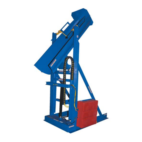
The drum dumper is powered by an electric motor directly coupled to a gear pump. The pump pressurizes the
hydraulic fluid. Fluid pressure causes the piston of the hydraulic cylinder to extend. Piston extension causes the
bottom of the chute to rotate until it is elevated above the top of the chute. A hydraulic manifold bolted directly onto
the gear pump houses the hydraulic control components. Each component is rated for 3,000psi working pressure.
Important components of the power unit include:
Electric motor: the motor is either AC powered (wall socket) or DC powered (battery). AC-powered motors can be
wired for either single-phase or three-phase operation. Regardless of phase configuration, every motor is dual-
voltage capable.
Gear pump: the pump shaft is directly coupled to the shaft of the electric motor. Several displacements are
available to match the horsepower of the motor selected.
Check valve: prevents backflow of fluid through the pump and to the reservoir. Because fluid can only flow in
response to an electrical signal from the pendant controller, the chute can maintain any position between the
raised and lowered configurations.
Pressure relief valve: opens a path for fluid to flow back to the reservoir if fluid pressure exceeds 3,000psi.
Lowering solenoid valve: electrically-operated cartridge valve with an integral screen to keep contaminants from
entering the valve.
Pressure compensated flow control spool: this feature regulates the flow of hydraulic oil from the cylinder back to
the reservoir. It is located beneath the lowering valve. This component allows the table to lower at a
predetermined constant rate regardless of the weight of the dumper and contents. Several sizes are available.
Displacement style hydraulic cylinder: each cylinder includes a bleeder valve located at top end for removing air
from the hydraulic system.
Velocity fuse: a safety device installed in the hose port of each cylinder. If a hose is punctured while the unit is
operating, the velocity fuse closes automatically. The chute remains stationary until pressure is reapplied to the
system.
Hydraulic fluid: HO150 hydraulic fluid. To replenish the fluid, add anti-wear hydraulic fluid with a viscosity grade
of 150 SUS at 100°F (ISO 32 @ 40°C) like AW-32 or Dexron transmission fluid.
Sequence of operation:
To raise/tilt the chute, press the white (UP) button. In response, the motor turns and rotates the gear pump. As
the pump rotates, oil is drawn from the reservoir, passes through the suction filter, and enters the pump.
The gear pump propels oil through the check valve to the lift cylinder.
Releasing the white button during operation immediately halts chute movement. Additionally, an electrical upper
travel limit switch automatically turns off the motor when the chute reaches a 45° angle to the ground (horizontal).
To lower the chute, press the black (DOWN) button.
Lowering valve opens which bypasses the check valve and allows oil in the cylinder to flow to the reservoir
(through return hoses). Oil flow to the reservoir is regulated by the pressure compensated flow control valve. By
regulating the volume of oil that can flow through the spool, the speed at which the chute lowers is kept constant.
Releasing the DOWN button during operation causes all chute movement to stop. The chute will remain in the
same position until you press either button on the pendant controller.