Heavy Duty
Electric Vibrators
800-633-0032
2215 Dunwin Dr., Mississauga, Ont. L5L 1X1
WARNING: Failure to read and follow these installation instructions and safety precautions could result in personal injury, equipment damage,
shortened service life or unsatisfactory equipment performance. All information in this document is vital to the proper installation and operation
of the equipment. It is important that all personnel who will be coming in contact with this product thoroughly read and understand this manual.
INSTRUCTION
MANUAL
©2019 VIBCO, Inc. IM_E_HD_19619
10 LUBRICATION
12 TROUBLESHOOTING
11 CHANGING OUTPUT SETTINGS
Warranty
All warranty claims must be submitted to VIBCO for approval prior to any repairs being done. Failure to do so will void any and all warranty coverage. All repairs will be
done at the VIBCO factory.
Errors, Shortages & Complaints
Complaints concerning goods received or errors should be made at once. Claims must be made within ve days after receipt of goods. Clerical errors are subject to cor-
rection. Damage during shipping must be reported to the carrier, not VIBCO.
Returning Parts **
Parts should not be returned to VIBCO without prior authorization. Call VIBCO’s customer service department at 800-633-0032 (800-465-9709 in Canada) for a Return
Goods Authorization (RGA) number. A return authorization will be emailed or faxed to you. Use this as your packing slip. Return shipping must be prepaid. Material
returned may be subject to a 10% restocking fee. All returned shipments should clearly display your name, address and original invoice number to ensure proper credit.
** Orders for custom equipment built to customer’s specications are not returnable.
Product Changes
VIBCO reserves the right to make changes in pattern, design or materials when deemed necessary, without
prior notice or obligation to make corresponding changes in previous models. To be sure of exact mounting
dimensions, it is recommended that you obtain a certied dimensional drawing from the factory.
Ordering Spare Parts
Parts can be ordered through authorized distributors or from VIBCO’s Spare Parts Department. The following
data should be provided when placing your spare parts order:
From label: Model number of unit.
From spare parts list: Reference number, part number, description & quantity required.
Shipping instructions: Specify shipping point and method of shipping.
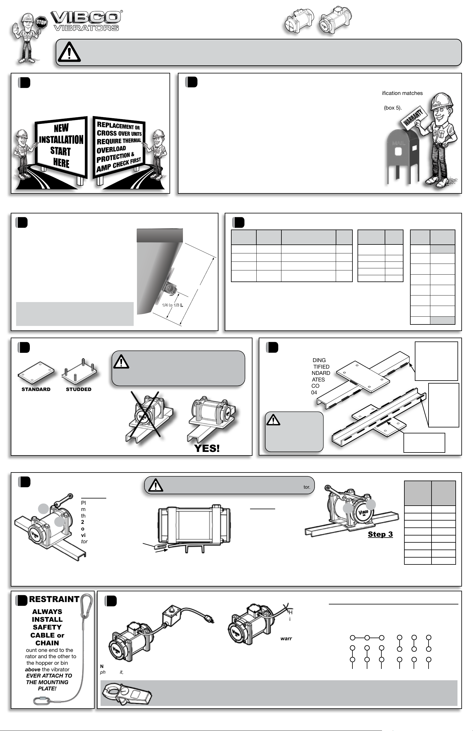
Models 2P-75, 2P-100, 2P-150, 2P-200, 2P-450, 4P-350,
4P-700, 4P-1000, and 6P-500 are pre-lubricated for life.
MODEL # INTERMITTENT
DUTY
CONTINUOUS
DUTY
2P-800, 2P-1700, 2P-2500,
2P-3500, 2P-4500, 2P-5500
Lubricate every
400-500 hours
Lubricate every
2 weeks
4P-1400, 4P-2000, 4P-3000,
4P-5000, 4P-10000
Lubricate every
1000-2000 hours
Lubricate every
4 weeks
6P-1000, 6P-1500,
6P-2500, 6P-5000
Lubricate every
1500-3000 hours
Lubricate every
6 weeks
8P-500, 8P-750,
8P-1250, 8P-2500
Lubricate every
3000-4000 hours
Lubricate every
8 weeks
HIGH TEMPERATURE
UNITS CONSULT FACTORY!
Grease Specications
Lubriplate Synxtreme HD-2 Calcium
Sulfonate Complex Grease. NLGI Grade 2.
Temperature range: -45° to 225ºF. Minimum
viscosity 90 -110 cSt at 40°C (104ºF).Use
2.5 to 3 grams (two pumps with standard
manual grease gun) per bearing. Do not
over grease! MY MATERIAL STILL ISN’T MOVING!
1. Did you put your vibrator in the right location? Did you mount
your vibrator properly?
2. Do you have the right vibrator for the job? Does it provide
enough force? Do you have the vibrator set to the maximum
force? (see left) Is it the right frequency? Still not sure? Call
VIBCO Technical Support at 800-633-0032.
THE VIBRATOR WON’T START!
1. Check power supply to unit. Are you getting the proper
voltage? Has the thermal overload protection tripped?
2. Check stator continuity, if “open” stator winding is burned or
has a short, replace stator. If unsure how to check continuity,
call VIBCO or consult a licensed electrician.
VIBRATOR STOPS RUNNING!
1. Check power supply to unit.
2. Has the thermal overload protection tripped? Single phase
units are supplied with overload switches. Three phase units
must be connected to three phase motor starters with proper
overload protection. If overload protection has tripped, wait a
minimum of two (2) minutes then reset by switching rmly off
and then on again.
3. Are you running the vibrator in a wet or wash down
environment? Consult VIBCO about wash down rated models.
4. Are you running the vibrator in a high temperature
environment? Consult VIBCO about high temp rated models.
Refer to full detail instructions for proper mounting in high
temp applications.
5. Are you running the vibrator continuously? All VIBCO heavy
duty models are rated for continuous duty but only at certain
eccentric settings. See diagrams to left for proper output force
settings for continuous duty.
NOTE: For best performance and vibrator life cycle, it
is best to run them intermittently. Consult VIBCO for
available timers.
6. Are you repeatedly stopping and starting the vibrator? This
can overload the vibrator. Use the following guidelines for
proper timing of starts and stops:
Single phase (2P-75, 100 & 150):
For run times of 10 seconds or less, use 1:7 ratio for run time
vs. off time. (example: 5 seconds on to 35 seconds off). For
run times longer than 10 seconds, use 1:1 ratio.
Single phase (2P-200, 450, 800; 4P-350, 700, 1000, 1400; 6P-300, 500):
These are capacitor start models and rated for a MAXIMUM
of 30 starts per hour.
Three phase:
For run times of 10 seconds or less, use 1:7 ratio for run time
vs. off time. (example: 5 seconds on to 35 seconds off). For
run times longer than 10 seconds, any cycle is acceptable.
NOTE: Proper force for full hopper can be excessive
for empty or near empty hopper.
MODELS: 2P-75, 100, 150, 200; 4P-350
MODELS: 2P-450, 800, 1700, 2500; 4P-600, 700, 1000, 1400, 2000, 3000, 5000, 10000
6P - ALL MODELS; 8P- ALL MODELS
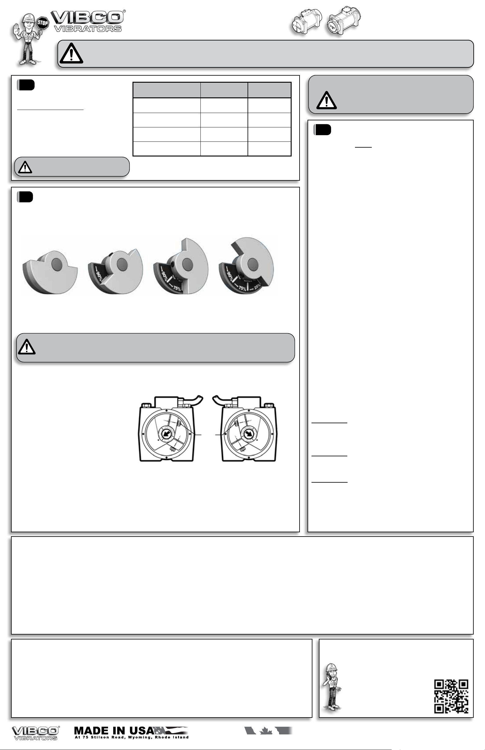
To adjust eccentric settings:
1. Remove both end covers from vibrator.
2. Loosen the bolt that holds the outer, labeled
eccentric to the shaft. NOTE: some models
have only one eccentric per side.
3. Turn the eccentric on the shaft to adjust force
output. Align the arrow on the shaft to the
desired setting. The higher the number, the
greater the force.
NOTE: You must set both ends of the
vibrator to the same setting.
4. Tighten eccentric bolts and reinstall end covers.
To produce linear motion you must make sure vibrators rotate opposite from one another. Force output labels
should be opposite to one another when viewed from the same side (one increases clockwise, the other counter-
clockwise as in picture above). Follow instructions as above, & be sure you set both vibrators & both ends to the same
setting. Consult VIBCO for more details.
NOTE: These vibrators are set to Setting #3 (Factory Setting).
LEFT RIGHT
BOLT
Settings 1 - 3 are continuous duty rated
Settings 4 - 6 are intermittent duty rated only
For vibrators mounted in tandem (side to side, not end-to-end)
to produce linear motion on table & feeder applications:
NOTE: If you INCREASE force of vibrator, you MUST take a new amperage draw reading to ensure vibrator is still
operating within specied limits.
NOTE: Only run intermittently when set to higher than factory set output forces (maximum running time of 30 min in
any one hour period).
ALWAYS DISCONNECT POWER SUPPLY BEFORE CHANGING SETTINGS! To increase or
reduce the force of your Small Impact Vibrator, remove the end cover and loosen the set screw that
holds the outer eccentric to the shaft and turn the outer eccentric so that it lines up with the desired
setting. Replace the end cover.
MINIMUM
25% OF FORCE
Optimum Setting for
Long Life of Vibrator
MAXIMUM
100% OF FORCE
Intermittent
Duty Only
90% OF MAXIMUM
Intermittent
Duty Only
75% OF MAXIMUM
Maximum Setting for
Continuous Duty
Skin temperature of vibrator should not exceed
180o F (82o C). If it exceeds this,
consult VIBCO for alternate solutions.
MAXIMUM OPERATING TEMPERATURE
For custom mounting
applications or any other questions:
800-633-0032
or
Use this handy QR Code to get
any of our Product Catalogs