VIBCO 50 User manual

Corporate HQ & Factory:
75 Stilson Road Wyoming, RI 02898
Phone: 800 633-0032 (401) 539-2392
Fax: (401) 539-2584
Western US:
Phoenix, AZ 85254
Phone: 800 633-0032 (480) 596-1809
Fax: (480) 596-1614
Canada:
2215 Dunwin Drive
Mississauga, ONT L5L 1X1
Phone: 800 465-9709 (905) 828-4191
Fax: (905) 828-5015
E-mail: [email protected]
Website: www.vibco.com
Mounting Instructions • Operating Instructions • Technical Data
Parts List • Troubleshooting
�
^
SILENT
Pneumatic Piston

Thank you for choosing VIBCO, Inc. for your vibration needs. You are now the owner of the
nest pneumatic piston vibrator available today, backed by complete manufacturer condence in
its quality and dependability. For reference, please complete the information below about your
new VIBCO vibrator.
Model Number: ____________________
Date of Purchase: ____________________
Safety Instructions & How It Works .............................................................................................2
Mounting Instructions: Checklist & Notes ..............................................................................3-4
Mounting Suggestions by Bin Type .........................................................................................5-8
Custom Mounting .......................................................................................................................8
Vibrator Installation and Pneumatic Hook-up ..........................................................................9-12
Operating Instructions ...............................................................................................................12
Troubleshooting................................................................................................................12-13
Technical Data and Dimensions
Model 50,55, & LI ...........................................................................................................14
Model 10, 30, 40, 70, 80 .................................................................................................15
Model 42 .........................................................................................................................16
Parts List and Breakdown
Model 50 .........................................................................................................................17
Model 55 .........................................................................................................................18
Model 10 .........................................................................................................................19
Model 30 .........................................................................................................................20
Model 40 .........................................................................................................................21
Model 70 .........................................................................................................................22
Model 80 .........................................................................................................................23
Model 42 .........................................................................................................................24
Warranty & General Information ................................................................................................25
TABLE OF CONTENTS
1
PHONE: 1-800-633-0032 FAX: 1-401-539-2584
WWW.VIBCO.COM [email protected]

Your new VIBCO pneumatic piston vibrator is constructed of fatigue-resistant steel alloys which
are heat treated to guarantee long service under high stress conditions. The at base plate
provides an efcient transmission of the shock energy to the system which is developed by the
reciprocating piston. The repetitive hammer action of the vibrator on the apparatus to which it is
attached is controllable by regulating the incoming applied air pressure.
Optional Features:
VIBCO pneumatic piston vibrators are available in many different congurations. Your piston
vibrator can be custom made to include features that will accomodate high impact, low noise,
high amplitude, and high temperature requirements. Some models (-EM sufx) are equipped
with an exhaust manifold to lead off exhausting air. Contact VIBCO if you would like more
information.
SAFETY INSTRUCTIONS
HOW IT WORKS
2
PHONE: 1-800-633-0032 FAX: 1-401-539-2584
WWW.VIBCO.COM [email protected]
WARNING: Failure to read and follow these installation instructions and safety
precautions could result in personal injury, equipment damage, shortened service
life or unsatisfactory equipment performance. All information in this document is
vital to the proper installation and operation of the equipment. It is important that
all personnel who will be coming in contact with this product thoroughly read and
understand this manual.
Thank you fo
r
choosing VIBCO
Vibrators.

Mounting Plate
For force up to 100 lbs. use a 1/4 in. thick plate, 100 to 500 lbs. use a 3/8 in. to 1/2 in. thick plate
and over 500 lbs. use a 1/2 in. thick plate.
MOUNTING INSTRUCTIONS CHECKLIST
3
PHONE: 1-800-633-0032 FAX: 1-401-539-2584
WWW.VIBCO.COM [email protected]
The warranty is void if vibrator is not properly installed. During installation follow and
check off the following steps and your vibrator should provide you with years of trouble-
free service.
NOTES ABOUT INSTALLATION
If you have any questions consult the Mounting Instructions section of this manual or call VIBCO
Technical Support at (800) 633-0032.
o Determine length of channel iron.
o Select thickness of mounting plate & method of mounting.
o STITCH weld mounting plate to channel iron.
o Determine vibrator placement on bin.
o STITCH weld channel iron to bin.
o Place vibrator on mounting plate.
Check the mounting plate for warping. Secure rmly.
o Install safety chain or wire.
o Connect pneumatics.
o FILL OUT WARRANTY CARD!!!!
PISTON DIAMETER " PLATE THICKNESS
5/8" to 1-1/4" 1/4" plate
1-1/2" to 2" 3/8" to 1/2" plate
3" to 4" 1/2" plate
CORRECT MOUNTING PLATES
SUGGESTED CHANNEL LENGTH
PISTON DIAMETER/BIN WALL WIDTH CHANNEL IRON WIDTH CHANNEL IRON LENGTH
5/8" to 1-1/4" / bin wall < 3/16" (thin) 3" channel iron 18" to 36" on both sides of vibrator
1-1/2" to 2" / bin wall = 3/16" 4" channel iron 3" to 4" on both sides of vibrator
3" to 4" / bin wall = 3/8" to 1/2" 4" channel iron 6" to 8" on both sides of vibrator
Mounting Channel
Never place the vibrator directly onto the skin of the bin. It should be mounted to either a plate or
a piece of channel iron that has been stitch welded to the bin. The proper mounting method is
to use either 3 in. or 4 in. channel iron. This will help to stiffen the structure to be vibrated as well
as spread the vibration over a larger surface, increasing the overall efciency and diminishing the
possibilities of fatigue cracks in the bin material.
The length and size of the channel iron is determined by the piston diameter. For 5/8 to 1-1/4 in.
diameters, use 3 in. channel iron and extend it 18 to 36 in. on both sides of the vibrator. 1-1/2 to
2 in. diameters should use 4 in. channel iron and extend it 3 to 4 in. on both sides of the vibrator.
3 to 4 in. diameters should use 4 in. channel iron and extend it to 6 to 8 in. on both sides of the
vibrator.

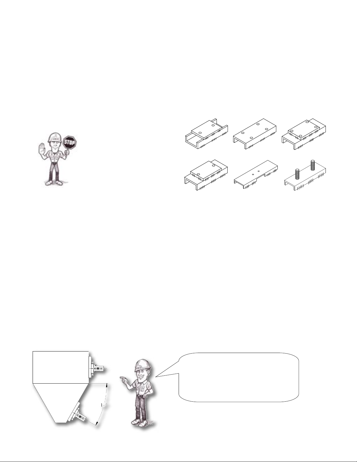
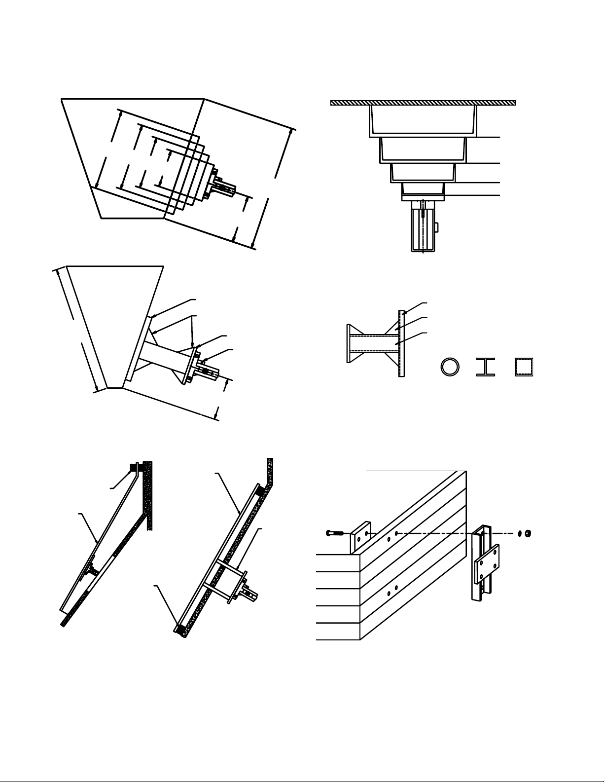
Different Suggestions for Mounting the Channel
1. Mounting plate welded to legs of channel iron.
2. 3 or 4 in. channel with holes drilled thru and nuts welded on back , or just holes drilled thru.
3. Mounting channel with mounting plate and holes drilled or tapped thru.
4. Notch the channel for access to mounting bolts.
5. Weld studs to back of channel.
NOTE: for a list of alternate mounting brackets, see pg. 35 of the VIBCO General Catalog.
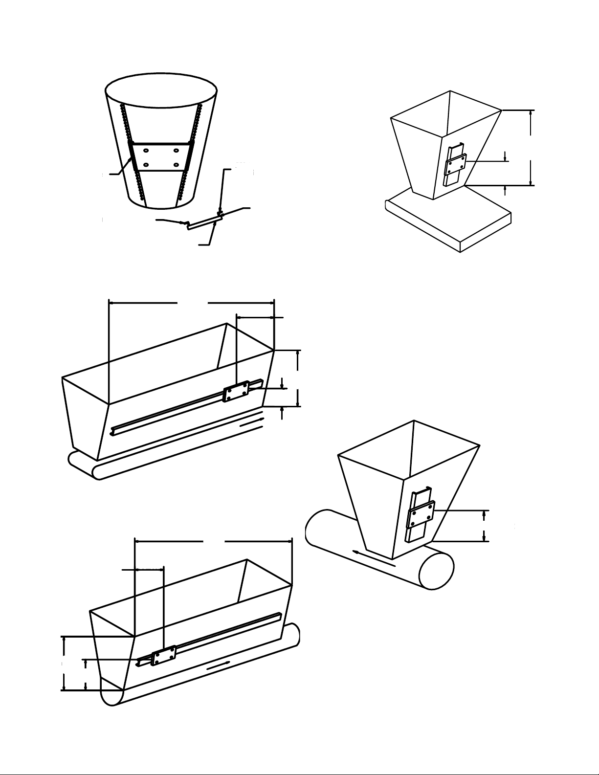
Placement
For coarse materials the vibrator should be mounted approximately 1/3 of the distance from
the discharge opening to the top of the sloped portion of the bin. For ne grain materials place
the vibrator approximately 1/4 of the same distance (see different mounting suggestions on the
following pages).
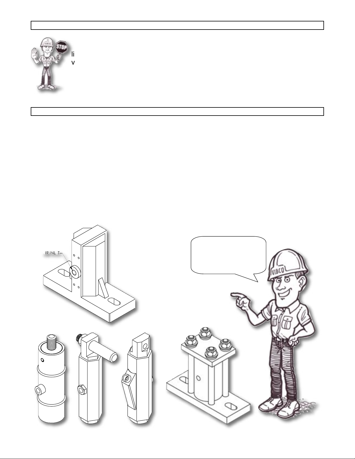
Welding Channel Iron to Bin
Where possible, the mounting plate or the channel iron should be placed 1/3 to 1/4 of the distance
from the discharge opening to the top of the sloped portion of the bin. Tack weld channel iron
in place, then weld intermittent welds 3 in. to 6 in. long with 3 in. between them along the entire
length of the channel. Stop weld a minimum of 1 in. from the ends. It is important that you do not
weld the ends of the channel iron. The heat concentration when welding the ends could cause
premature fatigue cracks.
Installing Safety Chain
It is important to install a safety chain or wire in order to prevent the vibrator from falling and
potentially causing injury if it comes loose from its mount.
1
54
3b
3a
2
4
PHONE: 1-800-633-0032 FAX: 1-401-539-2584
WWW.VIBCO.COM [email protected]
Always stop welds 1 in.
from ends to prevent heat
concentration and bin crack.
Stitch weld channel: weld 2 to
3 inches, skip 1 to 2 inches and
repeat until securely mounted.
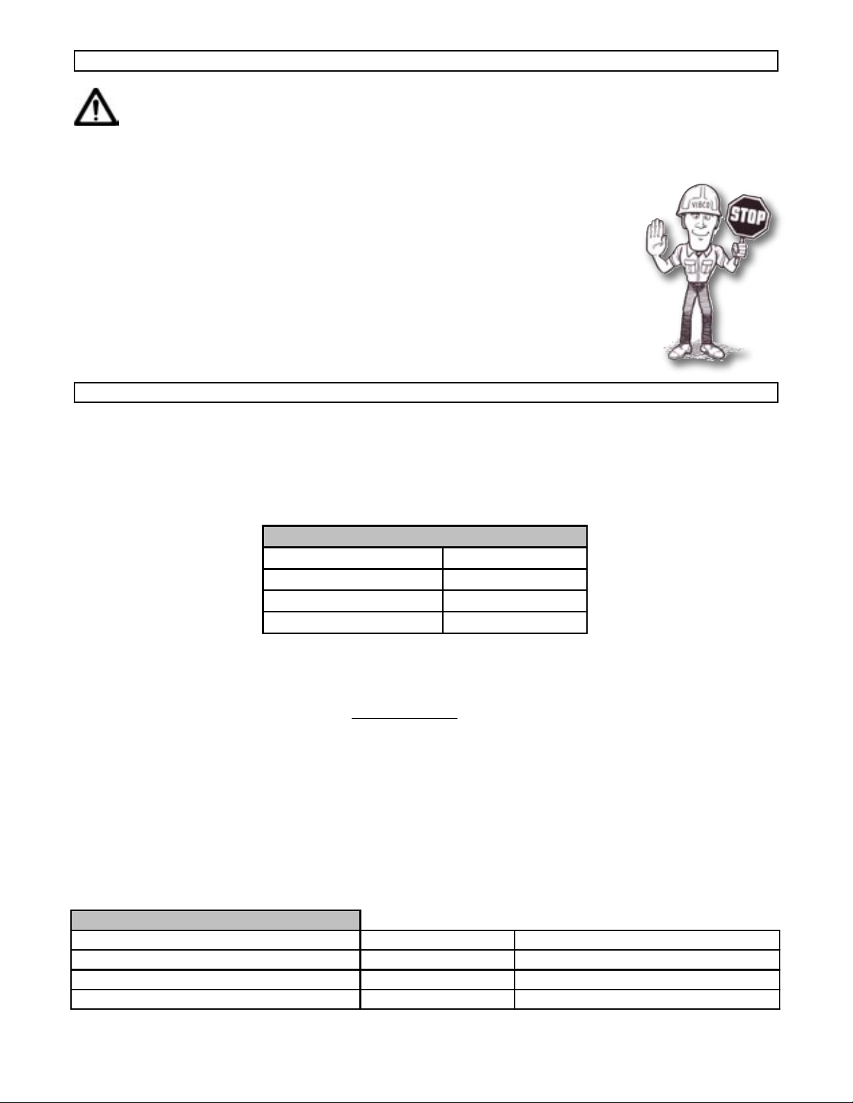
Standard piston models should
be mounted at least 15 degrees
from the ground. Anything less
than 15 degrees requires a
spring (-SP) model.
Welding Mounting Plate to Channel Iron
Stitch weld the mounting plate to the middle of the channel iron. If the bin plate is 3/16 in. or
less, weld the mounting plate to the back of the channel iron (see Figure 3 or 4). If the bin plate
is over 3/16 in. weld the mounting plate to the legs of the channel iron (see Figure 1). Drill and
tap holes or use studded plate (see Figure 1 or 5). Make sure the mounting plate does not warp
or distort. If this occurs, straighten, replace it or shim vibrator.
X

MOUNTING SUGGESTIONS
Conical
Bin
Rectangular
Bin
1/2 Rectangular
Bin
One Vibrator For A Double Bin
Bin With Stiffeners
Angle Iron Stiffeners
Instead of Channel Iron
Thin Skinned Bin
Corner Mount
5
Two Vibrators On
A Single Bin
PHONE: 1-800-633-0032 FAX: 1-401-539-2584
WWW.VIBCO.COM [email protected]
3/8” Gussets
Mounting Plate Vibrator
4 in. Channel
4 in. Square Tubing

Sheet Metal Bin Belt Conveyor and
Standard Bin
Long Bin
Belt conveyor feeds from the front. Vibrator
should be placed 1/3 from the front. If 2
vibrators are used, place second one directly
opposite 1/3 from the back. Do not operate
back vibrator until bin is empty in front and
the front vibrator has turned off. For more
details, consult VIBCO.
Feeds from back. Vibrator should be placed
1/3 from the back. If 2 vibrators are used,
place 2nd one directly opposite 1/3 from
the front. Do not operate front vibrator until
bin is empty in back and the back vibrator
has turned off. For more details, consult
VIBCO.
6
Belt Conveyors
Screw Conveyors
PHONE: 1-800-633-0032 FAX: 1-401-539-2584
WWW.VIBCO.COM [email protected]
Bolt To Bin
Angle Iron Feet
3/8 in. Mounting Plate
Weld Both Sides
Of Angle Iron
Drill Holes To Match
Bolt Pattern On Bin
W
1/3W
L
1/3L
As Close As Possible
Alternate Side
W
1/3W
L
1/3L
1/3L
L

Heat Mounts for Insulated Bins Containing High Temperature Materials: When materials in
the bin have a temperature over 150oF, it is advisable to use a “heat” mount to prevent excessive
heat from reaching the vibrator and causing overload or bearing failure. Also, ask for “high”
temperature grease in vibrator bearing. Consult VIBCO for vibrator size.
Wood Bin: Use steel plate on inside and bolt
to outside mounting channel.
Concrete Bin: Mount steel plate on inside of
bin so that the vibrator sits 1/3 up bin side.
Isolate the plate from the concrete by using
vibration shock absorbers. Consult VIBCO for
detailed drawings.
7
PHONE: 1-800-633-0032 FAX: 1-401-539-2584
WWW.VIBCO.COM [email protected]
2-1/2 TO 3 FT
2 FT
1-1/2 FT
1 FT
1/4 L
L
450-500o F
300o F
200o F
140o F
10 in. Channel Iron
8 in.
6 in.
4 in.
L
1/4 L
Channel Iron
Gusset
Mounting Plate
Vibrator
3 or 4 in. Channel Iron
Gusset
4 in. Pipe, I-Beam or Square Tube
Spacer
Rubber
Plate
Rubber
Plate

CHUTES: In order to successfully move material in a chute, the “angle of repose” of the material
has to be known. It can be found in most handbooks or can easily be measured by pouring a cup
of the material on a table. The angle between the table and the cone the material makes is the
“angle of repose”. To move the material in the chute, it should be inclined no less than 1/2 of the
“angle of repose” If this cannot be obtained, a feeder is necessary to move the material.
8
PHONE: 1-800-633-0032 FAX: 1-401-539-2584
WWW.VIBCO.COM [email protected]
CUSTOM MOUNTING APPLICATIONS
For custom mounting applications
Call 1-800-633-0032
or
E-mail [email protected]
• Force (impact) needed on vibrator is equal to weight of chute + vibrator + max material
in chute.
• Chutes must have an inclination of at least 10o for vibrators to be able to move the
material. If inclination is less the chute has to be made into a feeder. Contact VIBCO for
selecting the proper size vibrator or ask for the bulletin covering chutes.
• Chutes up to 6 ft. are generally handled by one vibrator mounted approximately 1/3 from
the discharge.
• On chutes over 6 ft. long, two vibrators are needed, one should be placed 18 - 24
inches from the discharge. The other approximately in the middle. Since chutes are
very sensitive to vibration, provision should be made to move the lower vibrator 6 inches
in either direction. This could mean the difference between moving the material or not
moving it.
For optimum performance follow these guidelines:
1/3 L
L = Up To 6 FT

Installation of the Vibrator
It is now time to put the VIBCO vibrator in place. Make sure that it is secured tightly. Retighten
the bolts after the rst 10 to 15 minutes of operation and check them periodically to maintain
proper tightness (gures 1 and 2).
VIBRATOR INSTALLATION
9
PHONE: 1-800-633-0032 FAX: 1-401-539-2584
WWW.VIBCO.COM [email protected]
Damage to the bin and the vibrator can occur if not mounted securely.
Remember:
Check those
bolts!
BOLT
SIZE
TORQUE
ft-lbs
1/4" 13
5/16" 25
3/8" 48
1/2" 115
5/8" 145
3/4" 260
FIGURE 1
FIGURE 2
Angle Iron Channel Iron

Flow Valve
A simple ow control valve is recommended to allow “tuning” the vibrator to the desired force.
The air ow determines the force and frequency of the vibrator. By throttling the air ow, you can
“nd” the desired material discharge rate. Watch for and avoid speeds (frequency) at which the
binwall and the vibrator shake violently. An increase or decrease of air ow usually stops the
excessive movement and will smooth out the operation, assuming the mount is rigid.
Quick Opening Valves
Recommended between the air regulator and the vibrator so the air enters the vibrator at full
starting force even with low regulator valve settings. The only requirement is that you install
the air regulator at least 12 inches away from the quick opening valve so that the air pressure
between the two valves will build up enough to yield the necessary starting force. Solenoid
(quick opening) valves are suggested for automatic operations. Automatic Timed Cycling is
programmed with the timer usually directly connected to the bin or hopper gate switch. When
the gate is opened the timed cycling system is activated.
Air Filter
It is recommended that you use an air lter in the line. Clean air will prolong the life of any
pneumatic vibrator. Dirty or moist air will harm the unit and impair it from operating at maximum
efciency and lowest air consumption.
Air Lubricator:
Lubricaton is required for the operation of the pneumatic piston vibrators. The lubricator should
be set at 1 drop for every 10 CFM the vibrator requires. Use SAE-10 oil or lighter.
Air Line To Vibrator
The hose to the inlet port of the vibrator should have the same or larger hose I.D. as the inlet I.D.
(pipe size) of the vibrator to minimize pressure loss from the compressor to the vibrator. Check
the technical data section of this manual, and nd the specications that meet your model to
ensure you have the correct sizes.
10
PHONE: 1-800-633-0032 FAX: 1-401-539-2584
WWW.VIBCO.COM [email protected]
PNEUMATIC HOOK-UP
PISTON
DIAMETER
MIN AIR
HOSE DIA
MIN FRL*
THREAD DIA CFM
5/8" to 1" 1/4" 1/4" 4 - 5
1-1/4" to 1-1/2" 3/8" 3/8" 9 - 11
2" & UP 1/2" 1/2" 15 - 50
* F=filter R=regulator L=lubricator
** these specs for installation of single unit;
for multiple units, adjust to maintain CFM
TO DETERMINE CORRECT AIR HOSE SIZE**
* F=lter R=regulator L=lubricator
** These specs are for installation of a single unit; for
multiple units, adjust to maintain CFM.
Use SAE-10 or lighter oil
1 drop per min for every 10 cubic ft/min (CFM)
LUBRICATION IS MANDATORY!
Timer
Flow
Valve
Air
Filter
Air
Regulator
Solenoid
Valve
To Control
Switch
To
Vibrator
To Gate
Air
Lubricator

11
Maximum Air Pressure
The operating pressure of the vibrator should not exceed 80 psi unless specially contructed for
higher pressure standards by VIBCO.
Maximum Temperature
The operating temperature of the vibrator should not exceed 200oF (93oC). High temperature
units are available.
PHONE: 1-800-633-0032 FAX: 1-401-539-2584
WWW.VIBCO.COM [email protected]
Contaminated air will shorten the life of the vibrator considerably, and will clog the critical
clearance between the cylinder and the piston. It will also increase the wear of the piston,
increasing the air consumption and diminishing vibrator efciency.
Water in the air line will reduce the effectiveness of the lubrication necessary to make the unit
operate and lubricate properly.
Water, dirt and air line rust at air pressures over 80 psi will create a sludge similar to grinding
compound and will wear down the piston and the cylinder very quickly.
IMPORTANT CONSIDERATIONS FOR LONG OPERATING LIFE
Figure 4
Figure 3
Not Recommended
Safe Operation
200o93o

To Obtain Maximum Performance
It is not necessary to operate the vibrator at its maximum capacity to obtain maximum performance.
Air regulators, timers, etc. should be used to tune the vibrator for optimum performance and
ensure longer life.
Continuous vs. Intermittent Operation
For bulk material bin applications, the vibrator should be used to reduce the material friction and
increase ow, not as a feeder. Once the friction of the particles is reduced, gravity ow takes
over and the vibrator should then be turned off for several reasons:
Economy. Most vibrators are run 60% to 80% longer than they should. Short bursts of vibration
are usually more effective than operating continuously. Experience has shown that for most
applications, short bursts of 10 to 30 seconds for every 1 to 5 minutes of discharge are more
effective and efcient.
Life of the Unit. The life of the vibrator will be determined by the length of operation and the
cleanliness of the air supply.
Guaranteed Success of the Application. The vibrator can only furnish material to the
discharge area. If more is furnished than conveyed, the remaining material will pack inside the
bin. We suggest the vibrators only run when the bin gates or doors are open, or when material
ow is needed.
OPERATING INSTRUCTIONS
12
PHONE: 1-800-633-0032 FAX: 1-401-539-2584
WWW.VIBCO.COM [email protected]
No oil in the air will cause the piston and cylinder walls to wear down rapidly, in some cases less
than 8 hours.
In extremely cold applications it is advised to mix antifreeze or kerosene with the oil.
Inject a small quantity of kerosene directly into the vibrator occasionally in order to clean out any
accumulated sludge.
Air pressure in excess of 80 psi will increase the velocity of the piston, diminishing the protective
oil lm and increasing the unit wear.
TROUBLESHOOTING
The Vibrator Won’t Start!
1. Check for dirt in the airline
2. Check to see if there’s any lubrication (remember 1 drop per minute per every 10 CFM)
3. Double check the size of your air line - is it large enough to give you the correct cubic feet per
minute (CFM) and correct air pressure (minimum required = 20 PSI)?
4. Did you mount the air regulator far enough away from the quick acting valve for the right
amount of air pressure to build up?
5. Is the vibrator mounted horizontally? If so, did you get the model with the spring?

The improper welding of vibrator to bin stiffeners often results in fatigue cracks in the bin. This
can be prevented by properly welding stiffeners to the bin side. A stiffener should be stitch
welded to the bin leaving 3 to 4 inches between welds. STOP WELDS 1 IN. FROM THE ENDS
OF THE STIFFENER. This will prevent fatigue cracks that occur due to crystalization of the
material. This crystalization is caused by the heat concentration that develops when the ends of
the channel iron are welded. To stop the cracks, drill a hole at the end of each crack and weld on
a piece of angle iron as shown above. When welding the angle iron STOP WELDS 1 IN. FROM
THE ENDS.
3 or 4 in.
channel
Do not weld 1 in. from
end of stiffener
Mounting plate
for vibrator
Stop welds at
least 1 in. from
ends
If cracks have developed, drill holes at the ends of the
cracks and weld on angle iron as shown
13
PHONE: 1-800-633-0032 FAX: 1-401-539-2584
WWW.VIBCO.COM [email protected]
Field repairs of piston vibrators are limited to replacing bolts, nuts, washers, o-rings and rubber
shocks. Any other repairs should be done at VIBCO.
Bolt breakage is caused by:
1) Air pressure in excess of 80 psi.
2) Loose mounting bolts.
3) Excessive movement of vibrator on hopper or bin caused by:
A) Too exible hopper or bin that cannot absorb vibration created.
B) Operation on empty hopper.
4) Dried up rubber buffers. Buffers are used to absorb shock energy and prolong bolt
life. Through aging the buffers will take a “set” and deteriorate. It is advisable to replace
all buffers and bolts at this time.
Rubber buffers should be replaced following these instructions. The bolts are not torqued but
tightened to compress the rubber buffers to dimension “A” of the chart.
Model "A" (in.)
50-1 3/16
50-1-1/4 7/32
50-1-1/2 9/32
50-2 1/4
50-2L 1/4
50-3 5/16
50-3L 5/16
50-4 3/4

MODEL 50, 55 AND LI TECHNICAL DATA
14
PHONE: 1-800-633-0032 FAX: 1-401-539-2584
WWW.VIBCO.COM [email protected]
Model Inch mm Inch mm Inch mm Inch mm Inch mm Inch mm Inch mm Inch mm
50-1 3-1/2 89 2 51 1/2 13 5/8 16 3/16 5 4-1/2 114 4-9/16 116
50-1-1/4 4-1/2 114 2-1/2 64 1/2 13 7/8 22 7/32 6 6 152 6-1/2 165
50-1-1/2 6* 152 3 76 3/4 19 7/8 22 9/32 7 7-1/2 191 7-15/16 202
50-2 6* 152 3-1/2 89 3/4 19 7/8 22 1/4 6 9 229 7-15/16 202
50-2L 6* 152 3-1/2 89 3/4 19 7/8 22 1/4 6 9 229 9-7/16 240
50-2EP 6* 152 3-1/2 89 3/4 19 7/8 22 1/4 6 9 229 *** ***
50-3 8-7/16 214 4-1/2 114 3/4 19 2-1/2 64 1 25 5/16 8 10-1/2 267 10-1/2 267
50-3L 8-7/16 214 4-1/2 114 3/4 19 2-1/2 64 1 25 5/16 8 10-1/2 267 13-1/2 343
50-4 8-7/16 214 5-1/2 140 1 25 2-1/2 64 1 25 3/4 19 10-1/2 267 11-5/8 295
55-1 3-1/2 89 2 51 1/2 13 5/8 16 4-1/2 114 3-7/8 98
55-1/4 4-1/2 114 2-1/2 64 1/2 13 7/8 22 6 152 5-5/8 143
55-1-1/2 7-1/2**** 191 3-1/2 89 5/8 16 1-1/8 29 9 229 7-1/4 184
55-2 7-1/2**** 191 3-13-16 97 5/8 16 1-1/8 29 9 229 7-1/4 184
55-3 7-3/4 197 5 127 7/8 22 3-1/4 83 1-1/8 29 10-1/2 267 9-7/16 240
LI-1-1/4 4-1/2 114 2-1/2 64 1/2 13 7/8 22 7/32 6 6 152 8-9/16 217
LI-2 6* 152 3-1/2 89 3/4 19 7/8 22 1/4 6 9 229 8-7/8 225
LI-3 8-7/16 214 4-1/2 114 3/4 19 2-1/2 64 1 25 5/16 8 10-1/2 267 13-1/2 343
-
-
-
-
-
-
-
-
-
-
-
-
-
3/8-NPT
1/2-NPT
1/2-NPT
-
-
-
-
-
-
-
-
-
-
-
-
**Bolt size
***See 50-2EP diagram
****Will also fit 6 in. center holes (see dimension A)
NOTE: Dimensions are subject to change without notice
I K
Air Inlet
*Also available with 7-1/2 in.
-
-
-
-
-
-
E F G HA B C** D
1/2-NPT
1/2-NPT
3/8-NPT
3/8-NPT
1/4-NPT
1/4-NPT
1/4-NPT
1/4-NPT
1/2-NPT
1/2-NPT
1/2-NPT
3/8-NPT
1/8-NPT
Air Inlet
1/4-NPT
1/4-NPT
1/4-NPT
1/4-NPT
Max lbs.
Piston Size CFM VPM CFM VPM CFM VPM Material in Bin (lbs)*
1S 3.5 3900 4 5400 5 6500 100-200
13.5 6500 4 9000 5 11000 200-400
1-1/4S 5 2400 7 3300 9 4200 200-400
1-1/4 5 4000 7 5500 9 7000 400-1000
1-1/2S 6.5 1700 9 2400 11 3200 400-1000
1-1/2 6.5 2800 9 4000 11 5200 1000-4000
2S 7.5 1950 12 2400 15 3000 1000-4000
27.5 3200 12 4000 15 5000 4000-10000
2LS 17 950 26 1200 31 1500 4000-10000
2L 17 1600 26 2000 31 2400 8000-20000
3S 18 1650 25 1950 30 2300 8000-20000
318 2700 25 3200 30 3800 10000-30000
3LS 31 800 42 900 51 1000 10000-30000
3L 31 1350 42 1500 51 1700 20000-70000
4S 33 1000 41 1200 50 1400 20000-70000
433 1400 41 1600 50 2000 Over 70000
containing dry, granular materials of 50 lbs/cu. ft. minimum bulk density. For other sizes and densities, contact
VIBCO.
80 PSI (5 Bar)60 PSI (4 Bar)40 PSI (3 Bar)
* This data is furnished as a guide in estimating the sizes of piston vibrators for standard hopper shapes
Model 50, 55 & LI Model 50-2EP & EPS

MODEL 10, 30, 40, 70, AND 80 TECHNICAL DATA
15
PHONE: 1-800-633-0032 FAX: 1-401-539-2584
WWW.VIBCO.COM [email protected]
Max lbs.
Piston Size CFM VPM CFM VPM CFM VPM Material in Bin (lbs)*
5/8 2.5 9500 3 12000 4.5 14500 Up to 100
3/4 3 7500 3.5 10500 5 13000 100-200
1S 3.5 3900 4 5400 5 6600 100-200
13.5 6500 4 9000 5 11000 200-400
1-1/4S 5 2400 7 3300 9 4200 200-400
1-1/4 5 4000 7 5500 9 7000 400-1000
1-1/2S 6.5 1700 9 2400 11 3200 400-1000
1-1/2 6.5 2800 9 4000 11 5200 1000-4000
2S 7.5 1950 12 2400 15 3000 1000-4000
27.5 3200 12 4000 15 5000 4000-10000
3S 18 1650 25 1950 30 2300 8000-20000
318 2700 25 3200 30 3800 10000-30000
standard hopper shapes containing dry, granular materials of 50 lbs/cu. ft. minimum bulk
density. For other sizes and densities, contact VIBCO.
40 PSI (3 Bar) 60 PSI (4 Bar) 80 PSI (5 Bar)
* The following data is furnished as a guide in estimating the sizes of piston vibrators for
Model Inch mm Inch mm Inch mm Inch mm Inch mm Inch mm Inch mm
10-5/8 5-1/2 140 1-1/4 38 5/16 8 1-5/16 33 1/2 12
10-3/4 5-1/2 140 1-5/8 41 3/8 10 1-3/8 35 1/2 12
10-1 5-5/8 143 1-7/8 48 3/8 10 1-7/8 48 1/2 12
10-1-1/4 9-1/4 235 2-5/16 59 1/2 12 2-5/16 59 11/16 18
10-1-1/2 9-11/16 246 2-1/2 64 5/8 16 2-15/16 75 7/8 22
30-5/8 6-5/16 160 1-1/4 32 5/16 8 1-5/16 33 1/2 12 5-7/16 136
30-3/4 6-5/16 160 1-5/8 41 3/8 10 1-5/16 33 1/2 12 5-7/16 136
30-1 6-9/16 167 1-7/8 48 3/8 10 1-7/8 48 1/2 12 5-7/16 136
30-1-1/4 10-1/2 267 2-5/16 59 1/2 12 2-5/16 59 11/16 17 9-1/8 228
30-1-1/2 11-3/8 289 2-7/8 73 5/8 16 2-15/16 73 7/8 22 9-1/2 241
40-1 6-3/16 157 1-7/8 48 1/2 13 2-3/4 70 7/16 11
40-1-1/4 9-1/2 241 2-5/16 59 1 25 4-3/4 121 3/4 19
70-5/8 4-3/4 120 1-1/4 32 5/16-24 M8X1.25 1-5/16 33 5/8 16 2-3/8 60 2-3/8 60
70-3/4 4-3/4 120 1-5/8 41 3/8-24 M10X1.5 1-5/8 41 5/8 16 2-3/8 60 2-3/8 60
70-1 4-3/4 120 1-7/8 48 1/2-20 M12X1.75 1-7/8 48 5/8 16 2-3/8 60 2-3/8 60
70-1-1/4 8 203 2-5/16 59 1/2-20 M12X1.75 2-5/16 59 5/8 16 4 101 4 101
80-1 4-1/2 114 1-1/2 38 1/2-20 - 2-1/8 54 1 25 2-1/2 64 2-1/2 64
80-1-1/4 5-1/8 130 1-3/4 44 5/8-18 - 2-1/8 54 1-5/16 33 2-13/16 71 2-13/16 71
80-1-1/2 6 152 2 51 5/8-18 - 2-1/2 64 1-5/16 33 4-1/8 105 4-1/8 105
80-2 8 203 2-1/2 64 7/8-14 - 3-1/16 78 1-3/8 35 4-1/8 105 4-1/8 105
NOTE: Data and dimensions subject to change without notice
A B C D E F G H* I
*For EM Models
Air Inlet
1/8-NPT
1/8-NPT
1/8-NPT
1/4-NPT
1/4-NPT
1/8-NPT
1/8-NPT
1/8-NPT
1/8-NPT
1/4-NPT
1/8-NPT
1/4-NPT
1/8-NPT
1/8-NPT
1/8-NPT
1/4-NPT
-
-
-
-
-
1/4-NPT
1/4-NPT
1/4-NPT
1/4-NPT
-
-
-
-
-
-
-
Air Exhaust
-
-
-
-
-
-
-
-
-
-
-
-
1/4-NPT
1/4-NPT
-
-
1/4-NPT
1/4-NPT
-
-
-
-
-
-
-
-
-
Model 10 Model 30 Model 40
Model 80Model 70

MODEL 42 TECHNICAL DATA
Model Inch mm Inch mm Inch mm Inch mm Inch mm
42-2 2-1/2 63.5 3-1/2 89 5-11/16 144 3/4 19 1/4 6.5
42-3 2-1/2 63.5 6 152 5-11/16 144 3/4 19 5/16 8
Inch mm Inch mm Inch mm Inch mm
5-7/8 150 10-1/8 257 8-5/16 211
7-3/4 197 13-7/16 341 8-1/2 216
NOTE: Dimensions are subject to change without notice
1/2-NPT
1/4-NPT
FE
G H I
ABD
L
Material Weigh
t
Model CFM
V
PM CFM
V
PM CFM
V
PM (lbs,)
42-2 7.5 3200 12 4000 15 5000 1000-4000
42-3 18 2700 25 3200 30 3800 8000-20000
materials of 50 lbs/cu.ft. minimum bulk density. For other sizes and densities, contact VIBCO.
40 PSI (3 BAR) 60 PSI (4 BAR) 80 PSI (5 BAR)
This data is furnished as a guide in estimating the sizes of piston vibrators for standard hopper shapes containing dry, granular
PHONE: 1-800-633-0032 FAX: 1-401-539-2584

17
!
"##!$%%!
&'(
)!*+,
*'+-.*+/!
(!*+,0
*'+
'1*+2!''3/
$''4
5!12/-(
0(!*+,+/!/'+222+/6' !3*#!'!'+. 3(!*+,*+4'/6
!"
"
!
"##!$%%!
&'(
)!*+,
*'+-.*+/!
(!*+,0
*'+
'1*+2!''3/
$''4
5!12/-(
0(!*+,+/!/'+222+/6' !3*#!'!'+. 3(!*+,*+4'/6
!"
"
PHONE ORDER: 1-800-633-0032 FAX: 1-401-539-2584
WWW.VIBCO.COM [email protected]

FAX: 905-828-5015
VIBCO, INC.
800-465-9709
P.O. Box 8
Wyoming, RI 02898
Phon : 401-539-2392
FAX: 401-539-2548
In Canada:
2215 Dunwin Driv
Mississauga, Ont. L5L 1X1
905-828-4191
800-465-9709
Model 55 Air Piston Vibrator
3
?
2
5
4
6
1 2 3 4 5 6
HOUSING SPRING PISTON O-RING PLUG SNAP RING
55-1" 100PS18 100PS32 100PS22/100PS26* 117 100PS05 5000-100
55-1 1/4" 125PS04 125PS07 125PS02/125PS06* 121 125PS05 5000-125
55-150 150PS19 150PS08+ 150PS20/150PS21* 218 150PS22 5000-150
55-1 1/2" 150PS04 150PS08
+
150PS02/150PS06* 218 150PS05 5000-150
55-2" 200PS04 200PS07
+
200PS02/200PS06* 224 200PS05 5000-206
55-3" 300PS04 300PS07
+
300PS02/300PS06* 232 300PS05 5000-300
+
ONLY AVAILABLE ON -SP MODELS *SILENT PISTON

19
! ! ! ! !
"
#"
!"
!
! ! ! ! !
"
#"
!"
!
PHONE ORDER: 1-800-633-0032 FAX: 1-401-539-2584
WWW.VIBCO.COM [email protected]
This manual suits for next models
7
Table of contents
Other VIBCO Industrial Equipment manuals
Popular Industrial Equipment manuals by other brands

Panblast
Panblast ZVP-PC-0075-01 Product Operating Manual

Pfeiffer Vacuum
Pfeiffer Vacuum HIPACE 1500 I Translation of the original

SMC Networks
SMC Networks IBG Series Operation manual

Siemens
Siemens LD-BV-KE-B-WP installation instructions

ixtur
ixtur MAP-40 Product instructions

Grant Fidelity
Grant Fidelity DAC-09 Modification Instructions

ABB
ABB HT584081 Operation manual

Schmalz
Schmalz SEAC 10 ECO operating instructions

Stratasys
Stratasys Finishing Touch Site preparation and installation guide

Allen-Bradley
Allen-Bradley Guardmaster LRTS installation instructions

Graco
Graco Xtreme L085C1 Repair and parts

Renishaw
Renishaw QUANTIC RESM40 installation guide