VICOR 3 Phase MegaPAC-ELTM User manual

UG:108 vicorpower.com Applications Engineering: 800 927.9474 Page 1
3 Phase MegaPAC-ELTM (Low Noise)
4kW MegaPAC-ELTM (Low Noise)
AC-DC Switchers
USER GUIDE | UG:108
September 2013
Overview
The 3 Phase MegaPAC - EL and 4kW MegaPAC - EL are field-configurable, single or
multiple output switchers, providing up to 2,000 W (3 Phase MegaPAC/EL- Low Noise)
to 4,000 W of output power (4kW MegaPAC/EL-Low Noise). The chassis has 10 slots
and provides up to 20 regulated, fully isolated outputs. It achieves power densities of
3.6 W per cubic inch (3 Phase MegaPAC/EL (Low Noise)) to 6.4 W per cubic inch (4kW
MegaPAC/EL (Low Noise). The dimensions for the 3 Phase MegaPAC/EL (Low Noise)
are 4.9"H x 7.5"W x 15.2"L (124,5mm x 190,5mm x 429,3mm) and the dimensions for
the 4kW MegaPAC/EL (Low Noise) are 4.9"H x 7.5"W x 16.9"L (124,5mm x 190,5mm x
386,1mm). The 4kW MegaPAC/EL (Low Noise) is longer than the 3 Phase MegaPAC/EL
(Low Noise) to accommodate a 2nd fan.
A complete power supply is configured by selecting and inserting up to ten same
length slide-in output assemblies called ConverterPACs. ConverterPACs incorporate
one or two VI-200/VI-J00 and/or MaxiVicor DC to DC converters and are available in
a wide selection of output voltage and power levels. The net result is a power supply
that oers the advantages of a custom supply, but is assembled from standard and
modular building blocks. For detailed information about all ConverterPACs, refer to
the ConverterPAC information sheets. The 4kW MegaPAC-EL (Low Noise) uses VI-200/
VI-J00 and Maxi Vicor DC to DC converters while the 3 Phase MegaPAC-EL (Low Noise)
uses VI-200/VI-J00 Vicor DC to DC converters.
Manufactured at Westcor, a division of Vicor, the entire family of MegaPAC power
supplies is completely user-configurable. If output requirements change, i.e., more
power or a dierent output voltage is needed, upgrading is easy: simply unlock a
single screw and replace the slide-in ConverterPAC with another Extended Length
ConverterPAC that has the desired voltage power rating. For additional flexibility, same
length ConverterPACs can be connected in parallel to increase output power (booster
ConverterPACs), or in series for higher voltages (total output voltage should not exceed
400 V). The driver is to the le of the boosters when looking at the output end of the
supply. A user-friendly interface provides control and output sequencing capability,
in addition to useful status indicators. Please consult our Applications Engineering
Department if you have other special requirements.
Contents Page
Overview 1
of Product
Mechanical 2
Considerations
MegaPAC 3
Do’s and Don’ts
Technical Description 4
Configuring and 5
Reconfiguring
MegaPACs
ConverterPAC 6
Description
Part Numbering 10
Quick Install 12
Instructions
Mechanical Drawings 15
Interface Connections 17
Specifications 24
Current Share Boards 26
Low Leakage Version 29
S
NRTL
CUS
CUS
®
3 Phase MegaPAC
4kW MegaPAC

UG:108 vicorpower.com Applications Engineering: 800 927.9474 Page 2
Standard Features
nInput: 3Æ 208/240 Vac Wye or Delta, 1Æ 180-264 (47-500Hz) or 260–352 Vdc
nPower Output: 3 Phase MegaPAC: 2,000 W with 3Æ input; 1,200 W with 1Æ input
4kW MegaPAC: 4,000 W with 3Æ input; 1,500 W with 1Æ input
n10 slots (upto 20 outputs)
nFan cooled (4kW MegaPAC-EL has 2 fans)
nFull power to 45°C; half power to 65°C
nPower Factor Correction - passive - to 0.92 PF (3Æ input)
nConducted EMI meets EN 55022 Level A
nAC Power OK and AC Power Fail status signals
nOutput Sequencing and General Shutdown
(Consult Applications Engineering for automatic sequencing circuitry.)
nAuto Sense capability Refer to page 12 and page 16 for more information on Autosense
nOvercurrent protection on all outputs
nOvertemperature limiting (not applicable with VI-J00)
nOvervoltage protection (not applicable with VI-J00 modules)
nSize: 3 Phase MegaPAC - EL: 4.9"H x 7.5"W x 15.2"L
(124,5mm x 190,5mm x 429,3mm) Extended chassis
Size: 4kW MegaPAC - EL: 4.9"H x 7.5"W x 16.9"L
(124,5mm x 190,5mm x 386,1mm) Extended chassis
nSafety Agency Approvals: cURus, cTUVus, CE Mark
Optional Features
nDC OK status signal
nOutput voltage adjustment range with built-in potentiometer
nReversed fan airflow direction
nCurrent Share Boards - see page 25
Mechanical Considerations
The 3 Phase MegaPAC - EL and 4kW MegaPAC - EL can be mounted on any of four
surfaces using standard 8-32 or 4mm screws. The chassis comes with four mounting
points on each surface; maximum allowable torque is 20 lb-in. The maximum
penetration is 0.15 in. (3,8mm).
When selecting a mounting location and orientation, the unit should be positioned so
air flow is not restricted. Maintain a 2" minimum clearance at both ends of the 3 Phase
MegaPAC - EL and 4kW MegaPAC - EL and route all cables so airflow is not obstructed.
The standard unit draws air in at the fan side/AC input side and exhausts air out the load
side. If airflow ducting is used, use caution, as sharp turns could present back pressure
to the 3 Phase MegaPAC - EL and 4kW MegaPAC - EL. For the 4kW MegaPAC - EL, the
fans move approximately 50 CFM of air while for the 3 Phase MegaPAC -EL, the fan
moves approximately 30 CFM of air. The 4kW MegaPAC - EL has a second fan for
additional cooling.
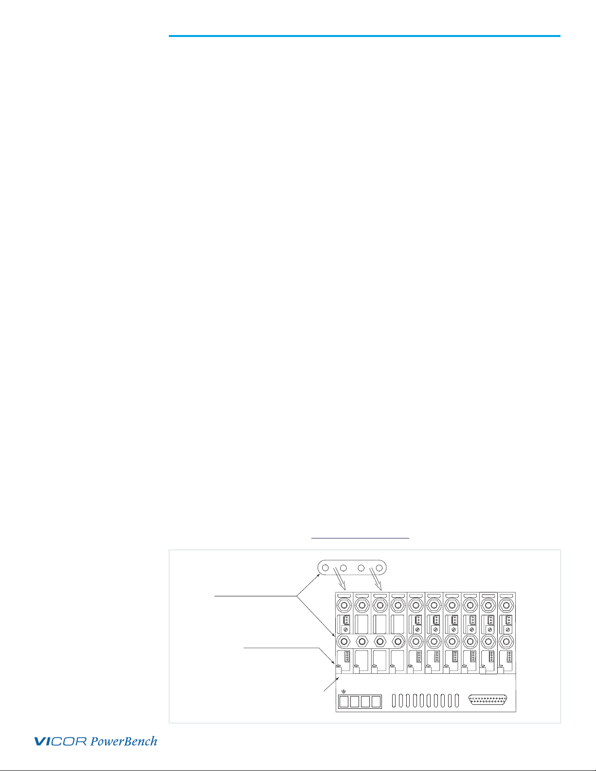
Avoid excessive bending of output power cables aer they are connected to the 3
Phase MegaPAC - EL or the 4kW MegaPAC - EL. For high-current outputs, use cable
ties to support heavy cables in order to minimize mechanical stress on output studs.
Be careful not to short-out to neighboring output studs. The 3 Phase MegaPAC - EL and

UG:108 vicorpower.com Applications Engineering: 800 927.9474 Page 3
4kW MegaPAC - EL are supplied with serrated, flanged hex-nuts on all output studs.
Therefore, thread locking compounds or lock washers are not required. The maximum
torque recommended on flanged nuts is 45 lb-in. Never loosen the inner nut on a
ConverterPAC. This nut supports the hardware inside the ConverterPAC and
is factory torqued.
Avoid applications in which the unit is exposed to excessive shock or vibration levels. In
such applications, a shock absorption mounting design is required.
MegaPAC Do’s and Don’ts
nFor units without Autosense, do not leave ConverterPAC Sense lines open. Always
terminate them to their respective outputs locally or at the load. Use twisted
pair 22-24 AWG wire. If ConverterPAC has Autosense, no local sense connection
is required. See page 12 and 16 for more information on Autosense.
nIf needed, use Connector Kit # 19-130041 for the 3 Phase/4kW
MegaPACs/EL - Low Noise.
nAlways fill all output slots of the MegaPAC. If a slot is not filled with a
ConverterPAC, it should be filled with an airblock. Airblocks are plastic assemblies
whose main function is to fill up an empty slot. Any airlfow escape from an empty
slot significantly degrades thermal performance, and can result in overheating and
damage to the power supply.
nDo not unplug ConverterPACs while input power is applied. They are not
designed for hot-plug applications.
nDo not restrict airflow to the unit. Leave 2 inch minimum space in front and
behind the supply. The cooling fan draws air into the unit and forces it out at the
output power terminals.
nFor power expansion, use booster ConverterPACs. Viewing the unit from the output
terminal side, always insert boosters to the right side of the driver.
nDo not use boosters as independent outputs. Disconnecting bus bars will damage
booster ConverterPACs.
nAlways ensure that output hex-nuts are properly torqued before applying
power to supply.
nFor booster arrays, do not remove busbars.
nRun the output (+/–) power cables next to each other to minimize inductance.
nWait 5 minutes aer shutting o power before inserting or removing ConverterPACs.
nThe MegaPACs does not have user serviceable components. They must be returned to
the factory for repairs. Contact Customer Service for a RMA number before returning
the unitDo not attempt to repair or modify the power supply in any manner other
than the exchange of ConverterPACs as described in this Design Guide.
nInsert proper fault protection at power supply input terminals (i.e., a fuse).
nUse proper size wires to avoid overheating and excessive voltage drop.
nNever loosen the inner nut on a ConverterPAC.
nVerify output nuts are tight before powering up.
nKeep in mind that the Regular Length ConverterPACs cannot be inserted in
the 3 Phase/4kW MegaPAC/ELs - Low Noise chassis because the Regular Length
ConverterPACs are too short to fit in the extended length chassis. The Extended
Length ConverterPACs are sometimes referred to as the QuietPAC (or QPAC)
Family of Low Noise ConverterPACs.
nCurrently, the QPAC (XQ) is only used in the 4kW MegaPAC/EL (Low Noise).

UG:108 vicorpower.com Applications Engineering: 800 927.9474 Page 4
Technical Description
The 3 Phase MegaPAC - EL and 4kW MegaPAC - EL are configured by installing same
length ConverterPAC assemblies into the chassis. The chassis takes AC input power and
performs filtering and rectification functions. The ConverterPACs plug into a high-
voltage backplane and provide low-noise, independently regulated and fully
isolated outputs.
Input AC mains voltage (L1, L2, L3 and GND) is applied to an agency approved mating
plug. The input current is passed through an EMI filter designed to meet EN 55022 Level
A before it is passed to a three-phase full-wave bridge rectifier. The rectifier charges
storage capacitors and delivers unregulated 300 Vdc to a backplane aer passing
through a large choke that improves input power factor. The power factor typically
exceeds 0.9 depending upon load, line voltage, frequency and line balance. Inrush
current is actively controlled with an IGBT and never exceeds 30 A peak regardless of
hot or cold starts or input volatage.
A housekeeping supply, isolated from the AC input, powers the brushless DC cooling
fan and other input monitoring circuits, in addition to providing an auxiliary +5 V
power source for the user. The 4kW MegaPAC - EL has a second fan for extra cooling.
Excessive input currents caused by loss of a phase or excessive output loading in single
phase operation will safely shut down the unit until input power is recycled. This occurs
when the peak input current reaches 30 A. An analog temperature monitor is provided,
as well as overtemperature shutdown. An active-high TTL compatible Enable control is
included for each ConverterPAC assembly, as well as an active-low General Shutdown
control; the polarities, active-high or active-low, are factory set. Two (or more) 3 Phase
MegaPAC - ELs can be safely paralleled with accurate current sharing for high power
systems. Two (or more) 4kW MegaPAC - ELs can be safely paralleled with accurate
current sharing for high power systems All interface signals are safety isolated using a
common floating return.
Upon power-up, all outputs are first disabled to limit the inrush current, and to allow
the unregulated bus to reach correct operating levels for ConverterPAC assemblies. The
internal housekeeping supply comes up within 500 ms aer input power is applied, and
the AC Power OK signal asserts to a TTL "1," indicating the input power is OK. The low
voltage power outputs come up within 10-20 ms aer the AC Power OK asserts to a
TTL "1." Output ramp-up time from Enable or General Shutdown is 10-20 ms.
Output fall time from Disable is dependent on load, but is typically a few hundred
microseconds.
Fuse
Isolated
Housekeeping
Power Supply
DC Brushless
Cooling Fan
EN 55022
Level A
3 Phase
Full-Wave
Rectifier
PFC Choke
IGBT
Opto-isolated
Control/Status
J10
Customer
Interface
J1
Input
Power
+P, -P
Output
Power
Remote Sense,
Trim Interface
Power Good
Interface
3 Phase/4kW MegaPAC/EL (Low Noise) Chassis QPAC ConverterPACs (Up to 10)
DC/DC
Converter
Start-up Control
Circuits
Figure 1.
3 Phase MegaPAC - EL and
4kW MegaPAC - EL Architecture
2nd Fan here
in the 4kW
MegaPAC-EL

UG:108 vicorpower.com Applications Engineering: 800 927.9474 Page 5
Configuring and Reconfiguring MegaPACs
Most ConverterPACs of the same length can be easily added, replaced, or moved
by sliding the assemblies in or out of a MegaPAC chassis. They are driver QPAC
ConverterPACs and can be inserted into any available slot. For outputs greater than
200 Watts, a driver QPAC and one or more booster QPACs will be used. For outputs
greater than 500 Watts, a driver QPAC (XQ) (in the 4kW MegaPAC - EL) and one or more
booster QPAC (XQs) will be used. Arrays of drivers and boosters should be configured so
all boosters are placed in the slots to the immediate right of the driver when looking at
the output end of the MegaPAC.
Prior to removing or installing ConverterPACs, you must remove power from the
MegaPAC and wait 5 minutes. Failure to do so can result in personal injury or
damage to the supply.
Take standard ESD precautions when handling ConverterPACs.
Removing QPAC ConverterPACs
ConverterPACs can be removed by loosening the captive screw at the base. Once
this screw has been loosened, the ConverterPAC will slide out of the chassis. Once a
ConverterPAC has been removed, the empty slot MUST be filled with either another
ConverterPAC or an airblock. If the slot is le empty, it will provide an airflow escape
and cause failure to the power supply.
Installing ConverterPACs as Drivers
ConverterPACs can be installed in empty slots by simply sliding in the new
ConverterPAC and securing the screw at the base. Power and interface connections can
be made aer the ConverterPAC has been installed.
Installing Booster ConverterPACs to Increase Output Power
Most ConverterPACs of the same length can be paralleled for more power. Additional
power to an output is obtained by connecting one or more boosters in parallel with a
single driver. The driver can be placed in any open slot. All boosters should be inserted
in the slots to the immediate right of the driver, as viewed from the output end of the
MegaPAC. Figure 2 shows a driver placed in slots #1 and 3 boosters placed in slots # 2 to
4. Aer inserting the driver and boosters, they are paralleled using bus bars across the
positive and negative output studs. Drivers should not be paralleled with each other. For
the 3 Phase/4kW MegaPAC/ELs (Low Noise), all the driver and booster ConverterPACs
must consist of the Extended Length ConverterPACs. Bus bars between a driver and
booster (s) should never be disconnected. For help in identifying boosters and drivers,
refer to the section on Part Numbering on page 9. Please note that total output voltage
should not exceed the converter baseplate-output isolation rating of 400 V. For detailed
guideline on how outputs should be placed in series, please refer to the Applications
note available on the website at www.vicorpower.com.
Driver
Bus Bars for Paralleling
Loosen screw to
remove ConverterPAC
Boosters: Slots 2, 3, 4
12345678
L1 L2 L3
910
Figure 2.
Paralleling ConverterPACs

UG:108 vicorpower.com Applications Engineering: 800 927.9474 Page 6
ConverterPAC Functional Description (See ConverterPAC Datasheet/Design Guide for
complete information on all ConverterPACs.)
ConverterPACs are the family of slide-in output assemblies used in MegaPAC power
supplies. Most ConverterPACs of the same length are interchangeable within a MegaPAC
or between dierent AC input MegaPAC chassis. They can be added, moved, or
changed as necessary. A key feature of the Extended Length ConverterPAC is the low
ripple and noise output to 10mV p-p or 0.15%, whichever is greater. The following
ConverterPACs can be used in the 3 Phase MegaPAC - EL and 4kW MegaPAC - EL.
QPAC (L or XQ)
The QPAC (L) and QPAC (XQ) output assemblies consist of a VI-200/VI-J00 and a Maxi
Vicor DC to DC converters respectively. They convert the unregulated high voltage bus
to the desired regulated output voltage. Each QPAC (L) can provide up to 200 Watts of
output power, and booster QPACs can be added in parallel for more power. Each QPAC
(XQ) can provide up to 500 Watts of output power and slave QPACs can be added in
parallel for more power. The QPAC (XQ) can only be used in the 4kW MegaPAC-EL (Low
Noise). An active preload ensures the DC to DC converter operates in its highest noise
performance range. As the load on the module increases, the preload removes itself
from the circuit. Ripple and common mode noise filters on the output reduce ripple
under any load condition to 10 mV p-p or 0.15%, whichever is greater. QPACs can only
be ordered in the extended length Low Noise MegaPAC products. Please note that for
all QPACs, the output voltage from either output terminal to chassis should not
exceed 400 Volts DC, or peak.
DualQPAC (LD)
The DualQPAC output assembly consists of two VI-J00 Vicor DC to DC converters that
provides two isolated output voltages. DualQPACs can provide up to 100 Watts of output
power from each output. An active preload ensures the DC to DC converters operate in
their highest noise performance range. As the load on the module increases, the preload
removes itself from the circuit. Ripple and common mode noise filters on the output
reduce ripple under any load condition to 10 mV p-p or 0.15%, whichever is greater.
DualQPACs can only be ordered in the extended length Low Noise MegaPAC products.
Please note that for all DualQPACs, the output voltage from either output terminal
to chassis should not exceed 400 Volts DC, or peak.
Junior QPAC (LJ)
The Junior QPAC output assembly consists of one VI-J00 Vicor DC to DC converters
that provide one isolated output voltages. The Junior QPAC can provide up to 100 Watts
of output power from each output and can only be ordered in the extended length Low
Noise MegaPAC products. Please note that for all Junior QPACs, the output voltage
from either output terminal to chassis should not exceed 400 Volts DC, or peak.
+
_
VI-200
QPAC (L)
QPAC (XL)
DualQPAC
Junior QPAC
VI-J00 VI-J00
VI-J00

UG:108 vicorpower.com Applications Engineering: 800 927.9474 Page 7
List of ConverterPACs used and their features
ConverterPAC OVP OCP OTL RS/AS* LS/AS* PG TrimPot
QPAC (L ) Std Std Std AS* AS* Opt Opt
QPAC (XQ)** Std Std Std Std Opt Opt Opt
DualQPAC (LD) N/A Std N/A AS* AS* Std N/A
Junior QPAC (LJ) N/A Std N/A AS* AS* Opt Opt
* See page 12 and 16 for more information on Autosense.
** Currently, the QPAC (XQ) can only be used in the 4kW MegaPAC/EL.
OVP Overvoltage Protection (latching) OCP Overcurrent Protection (auto-recovery)
OTL Overtemperature Limiting (latching) RS Remote Sense
PG Power Good (DC OK TTL Signal) LS Local Sense
AS Autosense

UG:108 vicorpower.com Applications Engineering: 800 927.9474 Page 8
ConverterPAC Output and Connector Pin Identification -
3 Phase/4kW MegaPACs/EL (Low Noise)
QPAC (L and XQ)
Jr. QPAC
DualPAC
QPAC (L and XL)
TERMINALS- MOLEX P/N: 39-00-0031
HOUSING- MOLEX P/N: 39-01-0073
CRIMP TOOL MOLEX P/N: 57005-5000
MATING HDWR:
+SENSE
POWER GOOD
SIGNAL GROUND
POWER GOOD INVERTED
Vcc IN
2
1
3
P2-PIN1
TRIM
4
5
-SENSE
7
6
OUTPUT ADJUST
P2 REMOTE SENSE TRIM/SC
& POWER GOOD
- VOUT
+ V0UT
J1-B-PIN1
(OUTPUT CONNECTORS)
1 AND 4 +V OUT
33 +R/SENSE 6 -R/SENSE
1
2
J1-A
TERMINALS- MOLEX P/N: 39-00-0039
HOUSING- MOLEX P/N: 39-01-2060
CRIMP TOOL MOLEX P/N: 11-01-0197
MATING HDWR:
6
5
4
2 AND 5 -V OUT
DUAL QPAC
POWER GOOD INVERTED
N/C
SIGNAL GROUND
POWER GOOD
Vcc IN
TRIM TOP
J1-A-PIN1
3 +R/SENSE 6 -R/SENSE
6
5
4
J1-B
2 AND 5 -V OUT
3
2
(OUTPUT CONNECTORS)
1 AND 4 +V OUT
1
TERMINALS- MOLEX P/N: 39-00-0039
CRIMP TOOL MOLEX P/N: 11-01-0197
HOUSING- MOLEX P/N: 39-01-2060
MATING HDWR:
TRIM BOT
5
3
2
4
1
7
6

UG:108 vicorpower.com Applications Engineering: 800 927.9474 Page 9
Part Numbering
3Ø MegaPAC-EL MP*xA-5xBxxx-EL
eg. MP4-510108-EL
MP = MP
xA= number of outputs
5= 3Ø MegaPAC - EL Prefix
xB= number of modules
xxx = assigned by Westcor
EL = Indicates extended length chassis for use with QPACs
4kW MegaPAC-EL MP*xA-4xBxxx-xG-xH-EL
With VI-200/VI-J00 eg. MP10-410008-23-EL
With Maxi eg. MX10-410008-23-EL
MP = MP
xA= number of outputs
4= 4kW MegaPAC chassis
xB= number of modules
xxx = assigned by Westcor
xG= Optional Code 2 = VI-J00 or VI-200 module in slot #1; 3 = Maxi in Slot 1
xH= Optional Code 2 = VI-J00 or VI-200 module in slot #10; 3 = Maxi in Slot 10
EL = Indicates extended length chassis for use with QPACs
* If a Maxi module is used, the part number changes from MP to MX.
ConverterPAC XxDV/xEAxF
eg. L15V/10A
eg. L15V/10ADFIL
eg. LD15V/6.7A-12V/8.3AT
X= ConverterPAC type - If RoHS precede with a “G”
L = QPAC LD = DualQPAC LJ = Jr QPAC XU = Maxi QPAC
XU = UniPAC (currently only used in the 4kW MegaPAC)
xD= Voltage out
xE= Current out (rounded to 1 decimal point)
xF= Can be multiple options* (see below)

UG:108 vicorpower.com Applications Engineering: 800 927.9474 Page 10
* ConverterPAC options
BBooster module MMilitary Grade module
DDC OK or Power Good1PPreload
FFull 50-110% output adjustment2RRAM external3
F1 50-107.5% output adjustment STrimpot removed for external BatPAC adjustment
F2 50-105% output adjustment T90-110% output adjustment4
F3 50-102.5% output adjustment T1 90-107.5% output adjustment
F4 50-100% output adjustment T2 90-105% output adjustment
F5 60-110% output adjustment T3 90-102.5% output adjustment
F6 70-110% output adjustment T4 90-100% output adjustment
F7 80-110% output adjustment T5 100-105% output adjustment
F8 90-110% output adjustment T6 100-110% output adjustment
F9 100-110% output adjustment V1 "VXI" low noise (150 mV or less) for 24 V outputs5
IIndustrial Grade module V2 "VXI" low noise (50 mV or less) for outputs <24 V
KCustom SRF module used V3 1% ripple for outputs >24 V
[1] D option: Optional for all ConverterPACs EXCEPT the DualPAC, BatPAC
[2] F option: Optional for all ConverterPACs EXCEPT the BatPAC and DualQPAC
[3] R option: When using an external RAM, components such as autosense resistors and local sense
jumpers must be removed before turning on the supply. In addition, in order to insure proper operation,
sense pins must be connected either locally or remotely after the RAM's output. For further information,
contact Applications Engineering.
[4] T options: Optional for all ConverterPACs EXCEPT the BatPAC and DualQPAC
[5] V options: Optional ONLY on the ModuPAC, DualPAC and JuniorPAC. N/A on all other
ConverterPACs.

UG:108 vicorpower.com Applications Engineering: 800 927.9474 Page 11
3 Phase and 4kW MegaPAC-EL
“Quick Install” Instructions (For Mechanical Drawing, see page 14 & 15)
Mounting the 3 Phase MegaPAC-EL and/or 4kW MegaPAC-EL
nThe 3 Phase MegaPAC - EL and 4kW MegaPAC - EL can be mounted on any
of four sides.
nUse #8-32 or 4mm mounting screws. Maximum penetration should not
exceed 0.15" (3,8mm).
nA minimum of 2" (5,1cm) clearance must be maintained at either end of
the supply in order to insure proper airflow and cooling.
nMaximum allowable torque is 20 lb-in.
Input Connections
Input Power J1
nInput AC power is applied to terminal block J1 using mating receptacle
AMP #54483-4 with #53892-4 crimp or #54329-1 solder terminals provided.
nUse size 12 AWG wire with soldered terminals.
nA fuse or circuit breaker in the input line is required for safety reasons.
Output Connections
Power Connections
Installing ring lugs and/or bus bars on output studs:
nThe upper stud is Positive and the lower stud is the Return.
nRemove outer nut. Do not remove or loosen inner nut.
nPlace ring lug over output stud.
nReplace and tighten outer nut to a maximum torque of 45 lb-in.
Do Not Over-Tighten Nuts.
nVerify all output nuts are properly installed before turning on supply.
Installing power connectors on DualPACs (J1A and J1B):
nUse Molex mating receptacle #39-01-2060 with #39-00-0039 terminals povided.
nPins 1 and 4 are Positive, while pins 2 and 5 are the Return.
nAttach terminals to 18-24 AWG stranded wire using Molex tool #11-01-0197.
QPAC (L)
P2-PIN1
OUTPUT ADJUST
- VOUT
+ V0UT
(OUTPUT CONNECTORS)
1 AND 4 +V OUT
33 +R/SENSE 6 -R/SENSE
1
2
J1-A
6
5
4
2 AND 5 -V OUT
3 +R/SENSE 6 -R/SENSE
6
5
4
J1-B
2 AND 5 -V OUT
3
2
(OUTPUT CONNECTORS)
1 AND 4 +V OUT
1
Input Panel Connectors
Single Output ModuPAC
DualPAC Output Connector
J1-4 Earth Ground
J1-1 Line 3
J1-2 Line 2
J1-3 Line 1
J1

UG:108 vicorpower.com Applications Engineering: 800 927.9474 Page 12
3 Phase and 4kW MegaPAC-EL “Quick Install” Instructions (Cont.)
Sense Connections
Note: Newer power supplies may have a new feature installed called Autosense. For
units with Autosense, if Remote Sense connections are not made or needed, no Local
Sense selection is necessary - simply connect the output to the load and the unit will
automatically operate in Local Sense. If Remote Sense connections are made, the unit
will operate in a Remote Sense mode. Remote Sense terminals should be terminated to
their respective outputs i.e. - RS to - Output and + RS to + Output. See page 16 for more
information on Autosense.
For units without Autosense, sense connections must always be made. Not
connecting Sense lines to their respective outputs can cause failure to the unit.
Sense Connections on QPACs and Junior QPAC:
nSense connections do not have to be made if the Local Sense option has been ordered.
(An “L” aer the current rating means the Local Sense option has been installed;
e.g., L5 V/40 AL.)
nUse Molex mating receptacle #39-01-0073 and #39-00-0031 terminals provided.
nP2-7 is the +Sense and P2-6 is the -Sense.
nAttach terminals to 22-28 AWG twisted pair wire using Molex tool
#57005-5000.
nAttach opposite end of Sense lines to point where regulation is desired.
nVerify that Sense lines are not cross-connected before applying input power.
Sense Connections on DualQPACs:
nSense connections do not have to be made if the Local Sense option has been
ordered. (An “L” in the ConverterPAC part number means the Local Sense option has
been installed; e.g. D5 V/20 AL-12 V/4.2 AL.)
nSense connections are available on the P2 connector or the J1A and J1B
connectors. Either can be used.
nUsing J1A, J1B, pin 3 is the +Sense and pin 6 is the -Sense.
nUse Molex mating receptacle #39-01-2060 with #39-00-0039 terminals provided.
nAttach terminals to 18-24 AWG stranded wire using Molex tool #11-01-0197.
nAttach opposite end of Sense lines to point where regulation is desired.
nVerify that Sense lines are not cross-connected before applying input power.
P2 Trim Connection for QPACs and Junior QPAC
nThe P2 remote Trim connection should only be used if the local Trim option has not
been installed. (A “T” or an “F” in the ConverterPAC part number means the Trim
option is installed; e.g. M5 V/40 AT.)
nP2-5 provides Trim access.
nUse Molex mating receptacle #39-01-73 with #39-00-0031 terminals provided.
nAttach terminals to 22-28 AWG stranded wire using Molex tool 57005-5000.
+SENSE
POWER GOOD
SIGNAL GROUND
POWER GOOD INVERTED
Vcc IN
2
1
3
TRIM
4
5
-SENSE
7
6
QPAC and Jr. QPAC
Sense Connectors
(OUTPUT CONNECTORS)
1 AND 4 +V OUT
33 +R/SENSE 6 -R/SENSE
1
2
J1-A
6
5
4
2 AND 5 -V OUT
3 +R/SENSE 6 -R/SENSE
6
5
4
J1-B
2 AND 5 -V OUT
3
2
(OUTPUT CONNECTORS)
1 AND 4 +V OUT
1
Dual QPAC
Sense Connectors
+SENSE
POWER GOOD
SIGNAL GROUND
POWER GOOD INVERTED
Vcc IN
2
1
3
TRIM
4
5
-SENSE
7
6
Trim Pin Connector
for QPACs and Jr. QPAC

UG:108 vicorpower.com Applications Engineering: 800 927.9474 Page 13
3 Phase and 4kW MegaPAC-EL “Quick Install” Instructions (Cont.)
P2 Trim Connection for DualQPACs
nThe P2 Trim connection should only be made if the Trim option has not been
installed. (A “T” or an “F” in the ConverterPAC part number means the Trim option is
installed; e.g. M5 V/40 AT.)
nP2-7 is Trim A and P2-6 is Trim B.
nUse Molex mating receptacle #39-01-0073 and #39-00-0031 terminals provided.
nAttach terminals to 22-28 AWG twisted pair wire using Molex tool #57005-5000.
DC OK (Power Good) for QPACs and Junior QPAC
nDC OK is only available as an option and is not always present.
nP2-3 is Power Good
nUse Molex mating receptacle #39-01-0073 with #39-00-0031 terminals provided.
nAttach terminals to 22-28 AWG stranded wire using Molex tool #57005-5000.
DC OK (Power Good) for DualQPACs
nDC OK is standard on DualQPACs and gives notice if either output fails to regulate.
nP2-3 is Power Good.
nUse Molex mating receptacle #39-01-0073 and #39-00-0031 terminals provided.
nAttach terminals to 22-28 AWG twisted pair wire using Molex tool #57005-5000.
Interface Connections J10
nJ10-7 to 11 and J10-20 to 24 are Enable/Disable for slots 1-10.
nJ10-16, 17 are Vcc, J10-12 and 15 are Signal Ground, J10-18 is AC Power OK,
and J10-5 is General Shutdown.
POWER GOOD INVERTED
N/C
5
3
2
4
1SIGNAL GROUND
POWER GOOD
Vcc IN
7
6
TRIM TOP
J2-PIN1
TRIM BOT
Trim Pin Connector
for DualQPAC
+SENSE
POWER GOOD
SIGNAL GROUND
POWER GOOD INVERTED
Vcc IN
2
1
3
TRIM
4
5
-SENSE
7
6
DC OK (Power Good) for
QPACs and Jr. QPAC
POWER GOOD INVERTED
N/C
5
3
2
4
1SIGNAL GROUND
POWER GOOD
Vcc IN
7
6
TRIM TOP
J2-PIN1
TRIM BOT
DC OK (Power Good)
for DualQPAC
Gate # 1 Input (isolated)
25
J10 INTERFACE CONNECTOR IDENTIFICATION
Analog Temperature
Overtemperature Warning
14
1
1615
234
191817
56
222120
78 9
2423
1110 12
Signal Ground1
Enable/Disable # 8
Enable/Disable # 10
No Connection
General Shutdown
Signal Ground
Signal Ground
Enable/Disable # 2
Enable/Disable # 4
Enable/Disable # 6
7
13
12
11
1O
9
8
4
6
5
3
2
13
A.C. Power Fail
A.C. Power OK
Vcc +5 volt, 300 mA
Vcc +5 volt, 300 mA
Signal Ground
Enable/Disable # 7
Enable/Disable # 9
Phase Fail
Gate # 10 (Output (Isolated)
Enable/Disable # 1
Enable/Disable # 3
Enable/Disable # 5
14
19
18
17
16
15
21
25
24
23
22
20

UG:108 vicorpower.com Applications Engineering: 800 927.9474 Page 14
3 Phase MegaPAC - EL Mechanical Drawings
4.90 (124.5 MM)
(EXAMPLE)
AIRBLOCK
-P8 TYP
IS SPECIFIED
ADJUSTABLE OPTION
PRESENT WHEN
R4 "TRIMPOT"
+P8 TYP
J1-PIN 1
J10-PIN1
10 PLACES
TO SECURE QPAC-200
#4-40 CAPTIVE SCREWS
.560 (14.2 MM)
6.56 (166.6 MM)
(18.5 MM)
9=SP @.7285
+P1 TYP
J2 PIN 1
-PI TYP
q
(6.1 MM)
.250
(29.2 MM)
(13.7 MM)
.54
1.15
L1 L2 L3
2.068
(30.5 MM)
1.20 (52.5 MM)
(47.0 MM)
1.852
.240
(47.0 MM)
1.852
10X 1/8 X 1/2 SLOTS
(10.2 MM)
.40
.46 (11.7 MM)
1.900
15A 47-440 HZ
208/240 VAC 3ÿ
LABEL LOCATED
APPROXIMATELY
(QPAC MODEL NO.)
AS SHOWN (TYP)
STANDARD AIR FLOW
3n
MegaPAC
WESTCOR
AS SHOWN
QPAC REMOVAL
APPROXIMATELY
LABEL LOCATED
SERRATED FLANGED NUTS
1/4 - 20 PLATED STEEL,
45 lbf-in
BOTTOM VIEW
1.20
5.10
(3.5 MM)
(129.5 MM)
(190.5 MM)
(12X) #8-32 PEMNUT
.15 MAX. PENETRATION
.150 (3.8 MM)
7.50
(57.2 MM)
(57.2 MM)
2.25
11.95 (303.5 MM)
12.28 (311.2 MM)
(57.2 MM)
6.50
(12.7 MM)
.50
2.25
(171.5 MM)
6.75
.65 (16.5 MM)
(35.6 MM)
1.40
(101.6 MM)
4.00
(15.2 MM)
.60
(165.1 MM)
6.75 (171.5 MM)
2.25
15.17 (385.31 MM)
6.75 (171.5 MM)
(4X) M4 TAPPED HOLE - TOP SIDES ONLY
.15 MAX. PENETRATION
(FOR #8-32 SCREWS ONLY)
V
COR
I

UG:108 vicorpower.com Applications Engineering: 800 927.9474 Page 15
4kW MegaPAC - EL Mechanical Drawings
4.90 (124.5 MM)
(EXAMPLE)
AIRBLOCK
-P8 TYP
IS SPECIFIED
ADJUSTABLE OPTION
PRESENT WHEN
R4 "TRIMPOT"
+P8 TYP
J1-PIN 1
J10-PIN1
10 PLACES
TO SECURE QPACS
#4-40 CAPTIVE SCREWS
.560 (14.2 MM)
6.56 (166.6 MM)
(18.5 MM)
9=SP @.7285
+P1 TYP
J2 PIN 1
-PI TYP
(6.1 MM)
.250
(29.2 MM)
(13.7 MM)
.54
1.15
L1L2L3
2.068
(30.5 MM)
1.20
(52.5 MM)
(47.0 MM)
1.852
.240
(47.0 MM)
1.852
10X 1/8
X 1/2 SLOTS
(10.2 MM)
.40
.46 (11.7 MM)
1.900
15A 47-440 HZ
208/240 VAC 3ÿ
---
LABEL LOCATED
APPROXIMATELY
4kW
MegaPAC
WESTCOR
AS SHOWN
QPAC REMOVAL
(QPAC MODEL NO.)
AS SHOWN (TYP)
APPROXIMATELY
LABEL LOCATED
SERRATED FLANGED NUTS
1/4 - 20 PLATED STEEL,
45 lbf-in
BOTTOM VIEW
1.20
5.10
(3.5 MM)
(129.5 MM)
(190.5 MM)
(12X) #8-32 PEMNUT
.15 MAX. PENETRATION
STANDARD AIR FLOW
7.50
(57.2 MM)
(57.2 MM)
2.25
11.95 (303.5 MM)
12.28 (311.2 MM)
(57.2 MM)
6.50
(12.7 MM)
.50 2.25
(171.5 MM)
6.75
.65 (16.5 MM)
(35.6 MM)
1.40
(101.6 MM)
4.00
(15.7 MM)
.62
(6.35 MM)
.25
(165.1 MM)
6.75 (171.5 MM)
2.25
16.72 (424.6 MM)
6.75 (171.5 MM)
(4X) M4 TAPPED HOLE - TOP SIDES ONLY
.15 MAX. PENETRATION
(FOR #8-32 SCREWS ONLY)
1.646 (41.8 MM)
V
COR
I

UG:108 vicorpower.com Applications Engineering: 800 927.9474 Page 16
Interface Connections
Chassis Input Power Terminals (J1)
Input AC power is applied to a plug-in connector, J1, that accepts soldered terminals
with a wire size of 12 AWG. For operation on high voltage DC input, input power can be
connected to any two input lines. A fault-clearing device should be installed at the input
of the unit. A user-accessible input fuse is not present within the unit. For an output of
2,000 W - 4,000 W with operation on 208 Vac, 3Æ input, a 20 A fuse in each input line is
acceptable. Input power cables should be shielded to minimize radiated noise eects.
Output Power Connections (+P, -P for Single Output, or J1A/J1B for Dual Outputs)
For single output ConverterPACs, these terminals are two 1/4-20 plated steel studs. The
upper stud is positive with respect to the lower stud. For dual output ConverterPACs,
there is a 6-pin Molex connector for each output. J1A pins 1 and 4 are the +Output,
and J1A pins 2 and 5 are the -Output. Pins 3 and 6 are the Remote Sense terminals. Use
appropriate wire size rated to handle the full output current, including short circuit
levels. Avoid large current loops in output cables; run power and return cables next
to one another to minimize inductive eects. All outputs are isolated and can provide
positive or negative outputs.
Output +/-Sense Connections (P2 for Single Output, or J1A/J1B for Dual Outputs)
Newer power supplies may have some outputs configured with the Autosense feature
that automatically locally senses the output if remote sense is not used. To check if an
output has the Autosense feature, measure the impedance from the + Out to + Sense and
- Out to - Sense pins. If the impedance is 5 ohms, then the output has Autosense and
does not require local sense jumpers.
For units without Autosense, sense connections must be made. When making sense
connections, keep in mind that although all outputs are open-Sense protected, the
+/-Sense terminals MUST be connected to their respective outputs before the 3
Phase MegaPAC - EL and 4kW MegaPAC - EL is powered up. Regardless of the output
polarity configured, the +Sense should always connect to the +Power output. The
-Sense connects to the -Power output. Sense connections are not required on booster
ConverterPACs, BatPACs, or if the Local Sense option is specified. Sense pins can be
accessed either on P2-6/P2-7 or J1A/J1B on dual output units.
Figure 3.
Input Panel Connector
J1-4 Earth Ground
J1-1 Line 3
J1-2 Line 2
J1-3 Line 1
J1

UG:108 vicorpower.com Applications Engineering: 800 927.9474 Page 17
Interface Connections (Cont.)
Signal Ground (J10-1, J10-2, J10-12, J10-15)
Signal Ground (see Figure 4) is an isolated ground reference for all J10 interface signals
used as a reference for ConverterPAC output status signals such as Power Good. This is
not the same as Earth Ground on input power connector J1.
Enable/Disable and General Shutdown (GSD)
The Enable/Disable control lines allow ConverterPAC outputs to be sequenced either
on or o. For DualQPACs, both outputs are sequenced. In parallel arrays, only the
driver ConverterPAC needs to be sequenced. The GSD control line on J10-5 allows
simultaneous shutdown of all ConverterPAC outputs. An internal factory-configured
jumper selects polarity, either active-high or active-low. Another jumper selects a pull-
up or pull-down source for the HCMOS control inputs.
The standard Enable/Disable controls are configured as active-low with internal pull-
up; outputs are enabled when these pins are open-circuited or allowed to exceed 4.5 V
with respect to Signal Ground. Outputs are disabled when the Enable/Disable control
lines are pulled low to less than 0.7 V. The GSD control line is configured to be active-low
with internal pull-up; all outputs are simultaneously inhibited when the GSD control
line is pulled low to less than 0.7 V. All outputs are enabled when GSD is open circuited
or allowed to exceed 4.5 V. The polarity of both the ED and GSD lines as well as pullup
or pull down can be reversed as a factory option per below diagramDo not apply more
than 5 V to these inputs at any time. The E/D and GSD circuits will sink up to 0.6 mA. If
driven from an electromechanical switch or relay, a small capacitor should be connected
between the control line and Signal Ground to eliminate latch-up due to the eects of
switch bounce (1mF, typical).
Figure 4.
Interface Connector (J10)
Gate # 1 Input (isolated)
25
J10 INTERFACE CONNECTOR IDENTIFICATION
Analog Temperature
Overtemperature Warning
14
1
1615
234
191817
56
222120
78 9
2423
1110 12
Signal Ground1
Enable/Disable # 8
Enable/Disable # 10
No Connection
General Shutdown
Signal Ground
Signal Ground
Enable/Disable # 2
Enable/Disable # 4
Enable/Disable # 6
7
13
12
11
1O
9
8
4
6
5
3
2
13
A.C. Power Fail
A.C. Power OK
Vcc +5 volt, 300 mA
Vcc +5 volt, 300 mA
Signal Ground
Enable/Disable # 7
Enable/Disable # 9
Phase Fail
Gate # 10 (Output (Isolated)
Enable/Disable # 1
Enable/Disable # 3
Enable/Disable # 5
14
19
18
17
16
15
21
25
24
23
22
20

UG:108 vicorpower.com Applications Engineering: 800 927.9474 Page 18
Interface Connections (Cont.)
Enable/Disable Control of Maxi Module Arrays
When using the Enable/Disable function on an output that consists of two or more Maxi
modules, it is necessary to connect the E/D pins of the corresponding module locations
together such that both modules are commanded to turn ON or OFF simultaneously.
Example: Slots 1 through 6 have been configured as a single output parallel array
(see Fig. 6)
In order to disable this array, E/Ds 1 through 6 should be shorted together as shown in
Fig. 6. With the E/Ds connected together, a single switch can then be used to remotely
enable and disable the output.
**Note: Note: For single output power supply configurations, the simplest method of remotely
enabling and disabling the output is to use the General Shutdown (GSD) function.
Figure 6.
Enable/Disable Control
of Maxi Arrays
L1 L2 L3
14
12
15 16
34
17 18
56
19 20
78
21 22
910
23 24
11 12
25
13
12345678 109
Figure 5.
Enable/Disable and
General Shutdown
10K
Signal Ground 1, 2, 12, 15
J10
General Shutdown 5
Enable/Disable Output #1 24
+5 Volt Vcc 16
10K
499
499
JP1 JP2
1 2
3
1 2 3

UG:108 vicorpower.com Applications Engineering: 800 927.9474 Page 19
Interface Connections (Cont.)
AC Power OK (J10-18)
This signal on J10-18 provides a status indication of the AC input power (see Figure 7).
It is active high, TTL compatible and capable of sourcing 10 mA maximum. This signal
switches to a TTL “1” when the high voltage bus exceeds low-line condition during turn-
on, and switches to a TTL “0” 3 ms (minimum) before loss of output regulation due to
the loss of input AC power. This signal can be used to warn external control circuits of
an impending loss of power.
AC Power Fail (J10-19)
J10-19 is the inverse of AC Power OK, and goes to a TTL “1” when the input AC power is
not OK. It is capable of sourcing 10 mA maximum. The fan out is 20.
Phase Fail (Input Overcurrent) (J10-14)
J10-14 is a TTL level active-high signal that is asserted when the peak input current
reaches 30 A due to the loss of an input phase or severe line imbalance. This occurs
when one input phase is lost with approximately 1,400 W output loading. Maximum
current that can be sourced is 10 mA.
Overtemperature Warning (J10-3)
J10-3 is a signal that asserts a TTL level "1" if the air temperature exceeds the following
factory set levels. The warning trip point is 65°C to 76°C, typically, and recovery point is
60°C to 71°C, typically.
Overtemperature Shutdown
If the inlet ambient air temperature exceeds the following factory set levels, the outputs
are disabled. The shutdown trip point is 70°C to 81°C, typically, and recovery point is
40°C to 48°C, typically.
Analog Temperature Monitor (J10-4)
This signal on J10-4, referenced to Signal Ground, provides an analog DC voltage output
between 0 V and 10 V that represents the air temperature of 0°C to 100°C inside the
power supply. The inlet air temperature is monitored close to the fan.
Figure 7.
AC OK/Power Fail
10K
1, 2, 12,15 Signal Ground
19 AC Power Fail
+5V J10
2.49K
2N
2222
2.49K
2
N222
2
2
N
222
2
14 Phase Fail
18 AC Power OK
4.99K

UG:108 vicorpower.com Applications Engineering: 800 927.9474 Page 20
Interface Connections (Cont.)
Gate IN/Gate OUT (J10-13, 25)
The 3 Phase MegaPAC - EL can be paralleled with other 3 Phase MegaPAC - ELs and the
4kW MegaPAC - EL can be paralleled with other 4kW MegaPAC - ELs to increase output
power. Paralleling the chassis is similar to paralleling VI-200 (QPAC-L) or Maxi
(QPAC-XQ) DC to DC converters. The Gate Out (or PC) pin of the ConverterPAC in slot
#10 is available on J10-25, and can be used to provide input to the Gate In (or PC) pin
of the ConverterPAC in slot #1 of a dierent 3 Phase MegaPAC - EL and 4kW MegaPAC -
EL. The ConverterPAC in slot #1 of the second chassis must be a booster, and additional
boosters can be connected in parallel to it. The ConverterPAC in slot #10 of the first 3
Phase MegaPAC - EL or the 4kW MegaPAC - EL must be either a driver or a booster in
a parallel array. ConverterPACs paralleled from chassis to chassis must be of the same
type, voltage, and power.
The 3 Phase MegaPAC - EL and 4kW MegaPAC - EL are configured at the factory to allow
box-to-box paralleling using the ConverterPACs originally shipped in the chassis. Since
the MegaPAC is a field configurable supply, the proper configuration must be verified
before paralleling from chassis to chassis. The last two digits of the 4kW MegaPAC - EL
part number will identify whether slot #1 and slot #10 were configured for use with
VI-200 (QPAC-L) or Maxi (QPAC-XQ) DC to DC converters.
Using the example of MX7-410108-32, the last two digits, "-32," identify the type of
module in slot #1 and slot #10, respectively. A "3" indicates the chassis is configured to
parallel box-to-box using a Maxi converter. A "2" indicates the chassis is configured to
parallel box-to-box using a VI-200 converter. The above example shows the chassis is
configured for a Maxi converter in slot #1 and a VI-200 converter in slot #10.
When connecting multiple chassis in parallel, the signal ground on J10 of each chassis
should be tied together. Chassis outputs should be tied together near the power supply
and then cabled to the load. Using separate cables to provide power to the load will limit
the supplies' ability to current share properly.
Auxiliary Vcc +5V/0.3A (J10-16, 17)
The Vcc on J10-16, 17 is an auxiliary 5 V regulated power source (see Figure 8 and
Connector Pin Identification of page 17). It is +5Vdc +/–5% with respect to Signal
Ground and can supply 300 mA maximum. It is short-circuit-proof, but if shorted all
outputs will shut down through the Enable/Disable circuitry. The Auxiliary Vcc typically
powers user circuitry or is used with the Power Good circuitry to provide a pull-up
reference for the outputs of the DC Power Good circuit on a ConverterPAC. If used for
this purpose, a J10 Signal Ground must also be connected to the P2-1 Signal Ground pin
of the ConverterPAC.
Figure 8.
Auxiliary Vcc
78M05 Auxiliary Vcc
16, 17
0.1 µF
Signal Ground
J10
1, 2, 12, 15
+5V/300 mA
This manual suits for next models
1
Table of contents
Other VICOR Switch manuals

VICOR
VICOR UG:106 User manual

VICOR
VICOR PFC MegaPAC User manual

VICOR
VICOR DC MegaPAC User manual

VICOR
VICOR FlatPAC-EN Guide

VICOR
VICOR FlatPAC-EN User manual

VICOR
VICOR PFC MegaPAC-EL User manual

VICOR
VICOR MegaPAC 3-Phase User manual

VICOR
VICOR 3 Phase MegaPAC User manual

VICOR
VICOR PFC Mini User manual

VICOR
VICOR FlatPAC Family AC Supplement
Popular Switch manuals by other brands

Alarm Controls Corporation
Alarm Controls Corporation 4152 installation instructions

Lindy
Lindy 38084 V2 user manual

The GigRig
The GigRig G3 quick start guide

NETGEAR
NETGEAR ProSAFE M6100 XCM8944 installation guide

Gefen
Gefen Digital Audio Switcher user manual

NETGEAR
NETGEAR GS750E Hardware installation guide