VICOR FlatPAC Family AC Supplement

FlatPAC Family
50 to 600 Watt
AC-DC Switchers
Application Notes
Functional and Mechanical Layout
Installation and Operation Guidelines
Product Description
The FlatPAC family of user-definable offline power supplies provides a complete
power solution that incorporates one, two, or three standard Vicor DC-DC
converters and a front-end subassembly in a modular package. FlatPAC is available
with one, two, or three outputs and total output ratings of 50–600 W. These power
supplies feature an autoranging input, which automatically senses the input line
voltage and sets the power supply’s input range accordingly. FlatPAC’s unique
modular design accommodates over 10,000 different configurations.
FlatPAC power supplies that contain BatMod current source modules instead of
VI-200 converters are indicated by the suffix -BM following the FlatPAC part
number. BatMod converters provide a programmable output current, rather than a
regulated output voltage. Consequently, the output supervisory terminal functions
differ on FlatPACs with BatMod modules.
U-Series

Product is internally fused
Application Notes
MOD DIS Input. Apply a current of
1–30 mA to disable output. Forward
voltage drop of internal opto diode is
1.65 V max. at 30 mA max.
AC OK and BUS OK Status Outputs.
Outputs low when OK.
Vce sat. = < 0.4 V @ 1.5m A. Maximum
external pullup is 70 Vdc. AC OK and
BUS OK signals are isolated and can
have different reference levels.
V
+r
AC OK
+
–
1.5mA
max.
V
+
r
BUS OK
+
–
30mA max.
Disable
MOD DIS
V
+
+
–
1.5mA
max.
FlatPAC
AC Mains and Supervisory Connections
External Supervisory Functions (2-up and 3-up models only)
MOD DIS –
MOD DIS +
AC OK –
AC OK +
BUS OK –
BUS OK +
Internal
Supervisory
Circuits
(Optocouplers)
AC Mains
Earth Ground
L1
L2/N
GND
2-Up
and
3-Up
1-Up
2

3
+Sense and –Sense must be connected locally or remotely (shown).
RESISTOR VALUES FOR TRIMMING STANDARD OUTPUT VOLTAGES
Nominal 5 V 12 V 15 V 24 V 28 V 48 V Trim Range
Output Voltage
R1(KΩ) .953 15.8 22.1 41.2 48.7 90.9 +10%, -10%
R2(KΩ) 90 90 90 90 90 90 +10%, -10%
VLINE > 90 (180)Vac
AC Line
Interrupted
AC
Line
AC OK
BUS OK
T0 T1 T2 T3 T4
Conditions: Full Load 90 (180)Vac, AC Line
Timing Diagram—Status Signals (2-up and 3-up models only)
Output Sense and Trim (All models with VI-200s)
Load
+
–
Battery
Charger
External
Control
Functions
Programmable Current
or Voltage Source
12–48V
Battery
+
–
+Out
VTRIM
ITRIM
IMON
–Out
External
Control
Functions
+Out
VTRIM
ITRIM
IMON
–Out
Typical Applications (Models with BatMods only)
Time Interval Min Typ Max Units Notes
T1-T0 0 0.1 1.0 ms
T3-T2 0 – – ms Ride-through time
T4-T2 5 – – ms Hold-up time
T4-T3 5 – – ms AC fail warning time
+Out
+Sense
Trim
–Sense
–Out
+ V
OUT
V
OUT
RTN
R2
R1
10K

Functional and Mechanical Layout
NU-, QU-, and RU-Series
MU-, PU-Series
LU-Series
Inputs
7
8
9
2.156 ±0.010
(54,76 ±0,25)
0.192 ±0.010
(4,88 ±0,25) 0.18
(4,57)
6.00
(152,4)
2.540 ±0.030
(64,52 ±0,76)
1.27
(32,26)
7
8
9
4.562 ±0.010
(115,87 ±0,25)
2.281 ±0.010
(57,94 ±0,25)
0.199 ±0.010
(5,05 ±0,25) 0.18
(4,57)
6.00
(152,4)
4.960 ±0.030
(125,98 ±0,76)
3.83
(97,16)
1.17
(29,72)
7
8
9
1
2
3
4
5
6
7.000 ±0.010
(177,8±0,25)
4.710 ±0.010
(119,63±0,25)
2.290 ±0.010
(58,17 ±0,25)
0.190 ±0.010
(4,83 ±0,25) 0.18
(4,57)
6.00
(152,4)
7.380 ±0.030
(187,45 ±0,76)
5.48
(139,19)
1.93
(49,02)
4
LU-Series
Single output
50-200 W
MU-Series
Single output
200-400 W
NU-Series
Single output
300-600 W
PU-Series
Dual output
100-400 W
QU-Series
Dual output
150-600 W
RU-Series
Triple output
150-600 W
Inputs
1 MOD DIS–
2 MOD DIS+
3 AC OK–
4 AC OK+
5 BUS OK–
6 BUS OK+
7 AC in L1
8 AC in L2/N
9 Chassis Ground
Outputs
10 +Power Out
11 +Out**
12 +Sense*
13 Trim*
14 –Sense*
15 –Out**
16 –Power Out
*On FlatPACs
containing BatMods:
12 VTRIM
13 ITRIM
14 IMON
**For local sense
connection only—
not for load
connection
FlatPAC units are shipped with pins 11-12
and 14-15 connected via jumper plugs
(Vicor P/N 02589) for local sense. For
remote sense, remove these connections
and connect pins 10-12 and 14-16, as
shown in the Output Sense and Trim
drawing on page 3.
All FlatPAC models are available
with a conduction cooled flat plate
instead of the top heat sink. Contact
factory for outline drawings.

NU-Series QU-Series RU-Series
MU-Series PU-Series
LU-Series
Outputs
All Models
1.375 ±0.020
(34,91 ±0,51)
0.50
(12,57) 9.245 ±0.030
(234,82 ±0,76)
1.11
( 28,19)
10
11
12
13
14
15
16
MOUNTING HOLE
ø 0.15 ±0.01 THRU
4 PLACES
OUTPUT 1
MOUNTING HOLE
ø 0.15 ±0.01 THRU
5 PLACES
10
11
12
13
14
15
16
10
11
12
13
14
15
16
10
11
12
13
14
15
16
OUTPUT 1 OUTPUT 2
+
+
–
10
11
12
13
14
15
16
10
16
10
11
12
13
14
15
16
10
11
12
13
14
15
16
10
11
12
13
14
15
16
10
11
12
13
14
15
16
10
16
10
16
10
11
12
13
14
15
16
MOUNTING HOLE
ø 0.15 ±0.01 THRU
6 PLACES
OUTPUT 1 OUTPUT 2 OUTPUT 3
OUTPUT 1
OUTPUT 1
OUTPUT 2
+
–
+
–
+
–
5
OUTPUT STUD CONNECTIONS
*SUPPLIED WITH FLATPAC
#10 WASHER*
USER OUTPUT
TERMINAL
#10 WASHER*
#10 LOCK WASHER*
#10 NUT*
#10 NUT* TORQUED TO
25 in-lbs (2.8 N-m)
AT THE FACTORY
DO NOT LOOSEN
Notes:
• Connect paralleled outputs as shown
(MU-, NU-, and QU-Series) for >40 A out.
• All output studs 10-32 UNF.
Torque to 20 in-lbs (2.3 N-m).
• Input supervisory terminals (1–6): use
mating connector Vicor P/N 33100,
AMP P/N 644083-6
• Output supervisory terminals (11–15):
use mating connector Vicor P/N 16385R,
AMP P/N 644083-5
• AMP Termination Tool Pistol Grip
Handle P/N 58074-1; with
interchangeable head P/N 58246-1
• Do not loosen bottom nut.

Installation and Operation Guidelines
Fusing. The FlatPAC’s internal fuses are not user-replaceable. Please return the
unit to vendor if servicing is necessary.
Grounding. To satisfy IEC 950 Class I grounding requirements, connect a ground
lead to the terminal marked (GND). For one-up FlatPAC models (max. output
200 W), use 1.5 mm2 / #16 AWG wire; for two-up and three-up models (max. output
400 W and 600 W), use 2.5 mm2 / #14 AWG wire.
Input Voltage Connections. Connect the line voltage to L1 (hot) and L2N (neutral).
For one-up FlatPAC models (max. output 200 W), use #16 AWG input wire; for two-
up and three-up models (max. output 400 W and 600 W), use #14 AWG input wire.
Recommended connector screw torque is 5 to 7 in-lbs (0.5 to 0.8 N-m).
Recommended strip length is 8 mm. Use your FlatPAC model only with the
corresponding input voltages and frequencies shown in the table below.
Model 90–132 Vac 180–264 Vac
C– Grade VI–■■U–C ■■47– 63 Hz 47– 63 Hz
I– Grade VI– ■■U– I ■■47– 440 Hz 47– 440 Hz
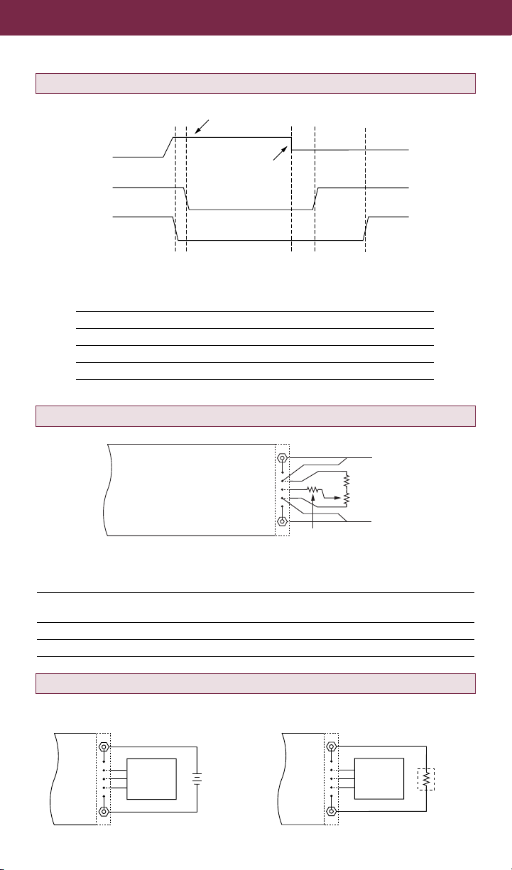
Output Wire Gauge. Use the output wire gauge that corresponds to the output
current of your FlatPAC unit, below: Do not loosen bottom nut.
100 A–160 A : #2 AWG 30 A–50 A : #8 AWG 10 A–15 A : #14 AWG
75 A–100 A : #4 AWG 20 A–30 A : #10 AWG 6 A–10 A : #16 AWG
50 A–75 A : #6 AWG 15 A–20 A : #12 AWG 0 A–6 A : #18 AWG
Output Voltage Trimming. Do not trim the outputs higher than 110% of their
nominal output voltage. When an output is trimmed up, do not exceed its maximum
rated output power.
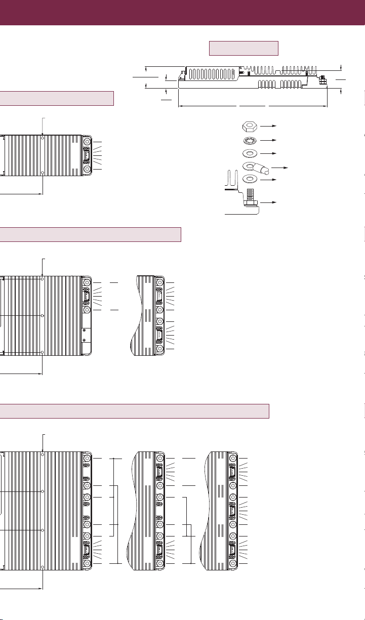
Operating Temperature. Do not allow the FlatPAC to exceed its maximum
operating temperature, which is reached when the heat sink is 85°C. (Full power can
be delivered up to this temperature.) Heat sink temperature is a function of the
output power and voltage of the supply, ambient temperature, and airflow across the
heat sink. Refer to the Vicor Applications Manual to determine the maximum ambient
temperature for your application. Always use worst-case conditions when
calculating operating temperature. Note 1: To ensure proper heat transfer from the
internal module(s) to the heat sink, the mounting holes through the heat sink (2, 3,
and 4 holes on one-, two-, and three-up models, respectively) must contain torqued
screws at all times during operation, whether or not the unit is mounted. If the unit is
operated unmounted, insert a #6 or metric panhead screw through each hole from
below and secure with a nut on top, torqued to 6 in-lbs (0.7 N-m). Note 2: All
FlatPAC models are available with a conduction cooled flat plate instead of the top
heat sink. Contact factory for outline drawings.
6

7
Input/Output Retrofit Connections. A hardware kit available from Vicor allows
the input and output supervisory terminals to be connected in the same manner as
for the earlier style FlatPAC (two-up model only). The retrofit output terminals are
sized to accept AMP Faston®insulated receptacle #2-520184-2.
For More Information
The Vicor Applications Manual and product data sheet contain complete information
about FlatPAC AC-DC power supplies. To receive literature or to consult an
applications engineer about installation or operation of this product, contact your
nearest Vicor office or visit the Vicor Website. (See back panel.)
(Bitte lesen Sie die Sicherheits-Vorschriften auf Seite 8.)
“AMP” and “Faston” are registered trademarks of AMP, Incorporated, Harrisburg, PA.
Input Retrofit Kit
Part Number: 14136
Output Retrofit Kit
Part Number: 14137

Printed in U.S.A. Pt. No. 24436 Rev 6.2 03/11
Sicherungen. Die internen Sicherungen im FlatPAC können nicht vom Anwender
ausgetauscht werden. Für Servicearbeiten schicken Sie das Teil bitte an den Händler
zurück.
Erdung. Um den IEC 950 Klasse I Erdungsforderungen zu entsprechen, muß ein
Erdungskabel an den Anschluß (GND) angeschlossen werden. Für FlatPAC
Modelle mit einem Modul (max. Leistung 200 W) benutzen Sie bitte 1.5 mm2AWG
16- und für Modelle mit 2 und 3 Modulen (max. Leistung 400 W und 600 W) bitte 2.5
mm2AWG 14-Kabel.
Betriebstemperatur. Die maximale Betriebstemperatur des FlatPAC-Gerätes darf
nicht überschritten werden. Dies ist gegeben, wenn der Kühlkörper eine Temperatur
von 85 Grad Celsius erreicht hat. Die Kühlkörpertemperatur ist eine Größe, die sich
aus der Ausgangsleistung und Spannung der Stromversorgung, der
Umgebungstemperatur und der Luftzirkulation über dem Kühlkörper ergibt. Bitte
bestimmen Sie mit Hilfe des Vicor Applikationshandbuches die maximale
Umgebungstemperatur Ihrer Applikation.
Weitere Informationen. Das Vicor Applications Manual und Produkt-Datenblätter
enthalten ausführliche Informationen über FlatPAC AC-DC Wandler. Fordern Sie
bitte Unterlagen bei Vicor oder Ihrer nächsten Vicor Vertretung an.
Sicherheits-Vorschriften
8
Vicor Corporation
Andover, MA, U.S.A
Tel: 800-735-6200
Fax:978-475-6715
Vicor France
Tel: +33-1-3452-1830
Fax:+33-1-3452-2830
Vicor Germany
Tel: +49-89-962-439-0
Fax: +49-89-962-439-39
Chicago, IL
Tel: 630-769-8780
Fax:630-769-8782
Vicor Italy
Tel: +39-02-2247-2326
Fax:+39-02-2247-3166
Vicor U.K.
Tel: +44-1276-678-222
Fax:+44-1276-681-269
Sunnyvale, CA
Tel: 408-522-5280
Fax:408-774-5555
Vicor Hong Kong
Tel: +852-2956-1782
Fax:+852-2956-0782
Vicor Japan Co., Ltd.
Tel: +81-3-5487-3880
Fax:+81-3-5487-3885
Visit Vicor’s Website at:
vicorpower.com
This manual suits for next models
3
Table of contents
Other VICOR Switch manuals

VICOR
VICOR 3 Phase MegaPAC-ELTM User manual

VICOR
VICOR PFC MegaPAC User manual

VICOR
VICOR PFC MegaPAC-EL User manual

VICOR
VICOR PFC Mini User manual

VICOR
VICOR FlatPAC-EN Guide

VICOR
VICOR 3 Phase MegaPAC User manual

VICOR
VICOR FlatPAC-EN User manual

VICOR
VICOR AC-DC Supplement

VICOR
VICOR MegaPAC 3-Phase User manual

VICOR
VICOR DC MegaPAC User manual