UG:123 Page 5
ConverterPAC™ Functional Description
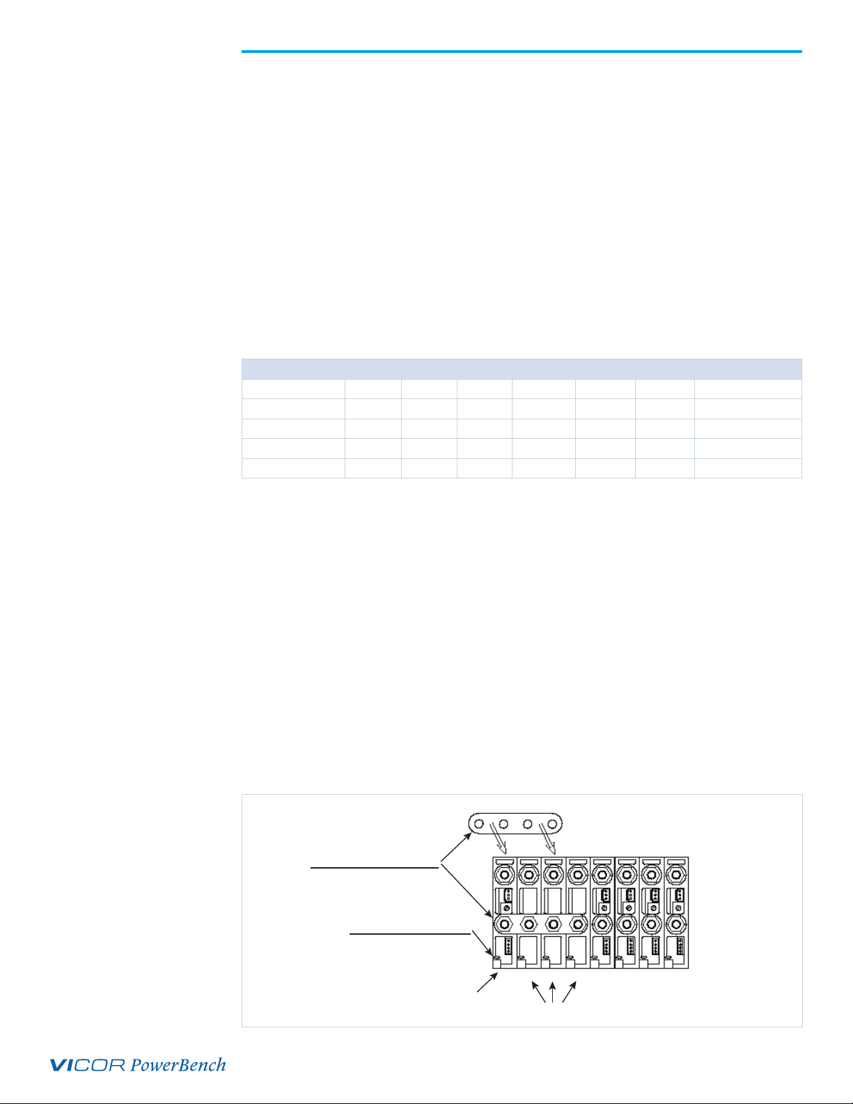
ConverterPACs are the family of slide-in output assemblies used in MegaPAC™power supplies.
ConverterPACs are interchangeable within a MegaPAC so they can be added, moved or changed as
necessary. They are also interchangeable between different AC input MegaPAC chassis. A ConverterPAC
removed from a Mini MegaPAC could be used in a three-Phase MegaPAC, for example. ConverterPACs
can be selected with a variety of options and in voltages from 2 – 95VDC.
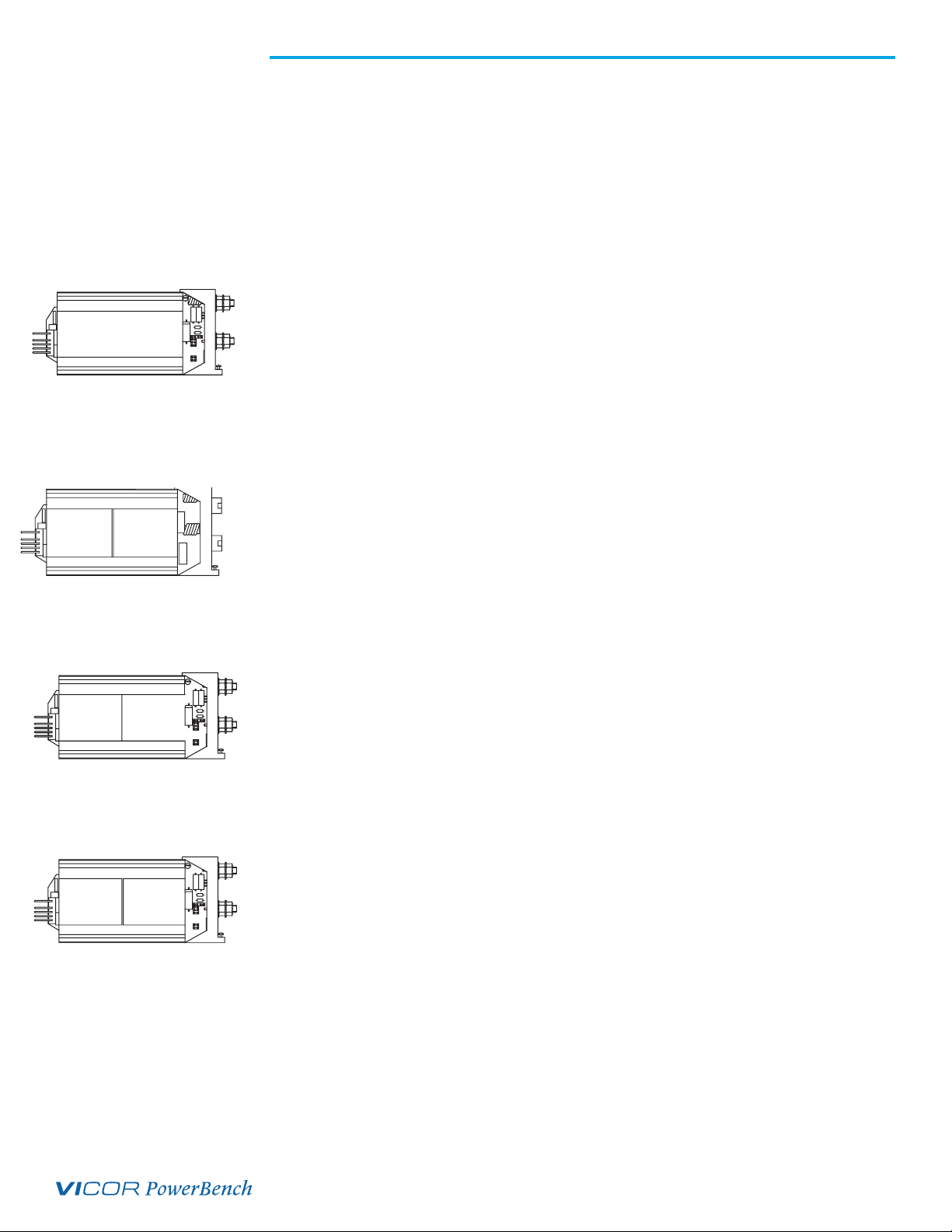
ModuPAC™
The ModuPAC output assembly consists of a VI-200 DC-DC converter that converts the high-voltage bus
to the desired regulated output voltage. Each ModuPAC can provide up to 200 watts of power. Multiple
ModuPACs can be paralleled in a driver-booster configuration to provide more power. ModuPACs are
fused with a PC-Tron, DC-rated, fast-acting fuse. A passive LC filter is used to reduce output ripple/noise
down to 1% typical, and 2% maximum peak-to-peak from 10% to 100% of rated load. An optional
DC Power Good signal or output voltage Trim potentiometer can be specified. The ModuPAC contains
overvoltage protection (OVP), overcurrent protection (OCP), and overtemperature protection (OTP). The
OCP has automatic recovery when the overcurrent condition is removed. The OVP and OTP are latching
functions and require recycling of the AC input power to restart.
DualPAC™
This output assembly consists of two VI-J00 DC-DC converters that convert the high-voltage bus to the
desired regulated output voltages. Each output on a DualPAC can provide up to 100 watts of power
and is fused with a single PC-Tron, DC-rated, fast-acting fuse. A passive LC filter is used to reduce output
ripple/noise down to 1% typical and 2% maximum peak-to-peak from 10% to 100% of rated load. An
optional output voltage trim potentiometer can be specified. DC Power Good signal is not available. The
DualPAC contains overcurrent protection, which recovers automatically when the overcurrent condition
is removed. Overvoltage and overtemperature protection are not available.
JuniorPAC™
The JuniorPAC consists of one VI-J00 DC-DC converter that converts the high-voltage bus to the desired
regulated output voltage. JuniorPACs can provide up to 100 watts of output power and are fused with
a single PC-Tron, DC-rated, fast-acting fuse. A passive LC filter is used to reduce output ripple/noise
down to 1% typical, and 2% maximum peak-to-peak from 10% to 100% of rated load. An optional
DC Power Good signal or output voltage trim potentiometer can be specified. The JuniorPAC contains
output overcurrent protection, which recovers automatically when the overcurrent condition is removed.
Overvoltage and overtemperature protection are not available.
RamPAC™
This output assembly consists of a VI-J00 DC-DC converter with a Ripple Attenuator Module (RAM) and
is designed for applications requiring low-output ripple/noise. The RamPAC can attenuate the ripple/
noise down to 10mV peak-to-peak over a 20MHz bandwidth from 10% to 100% of rated load of the
converter. Each RamPAC can provide up to 100 watts of output power, and outputs from 5 to 50V are
available. An optional DC Power Good signal or output voltage trim potentiometer can be specified. The
RamPAC contains output overcurrent protection, which recovers automatically when the overcurrent
condition is removed. Overvoltage and overtemperature protection are not available.
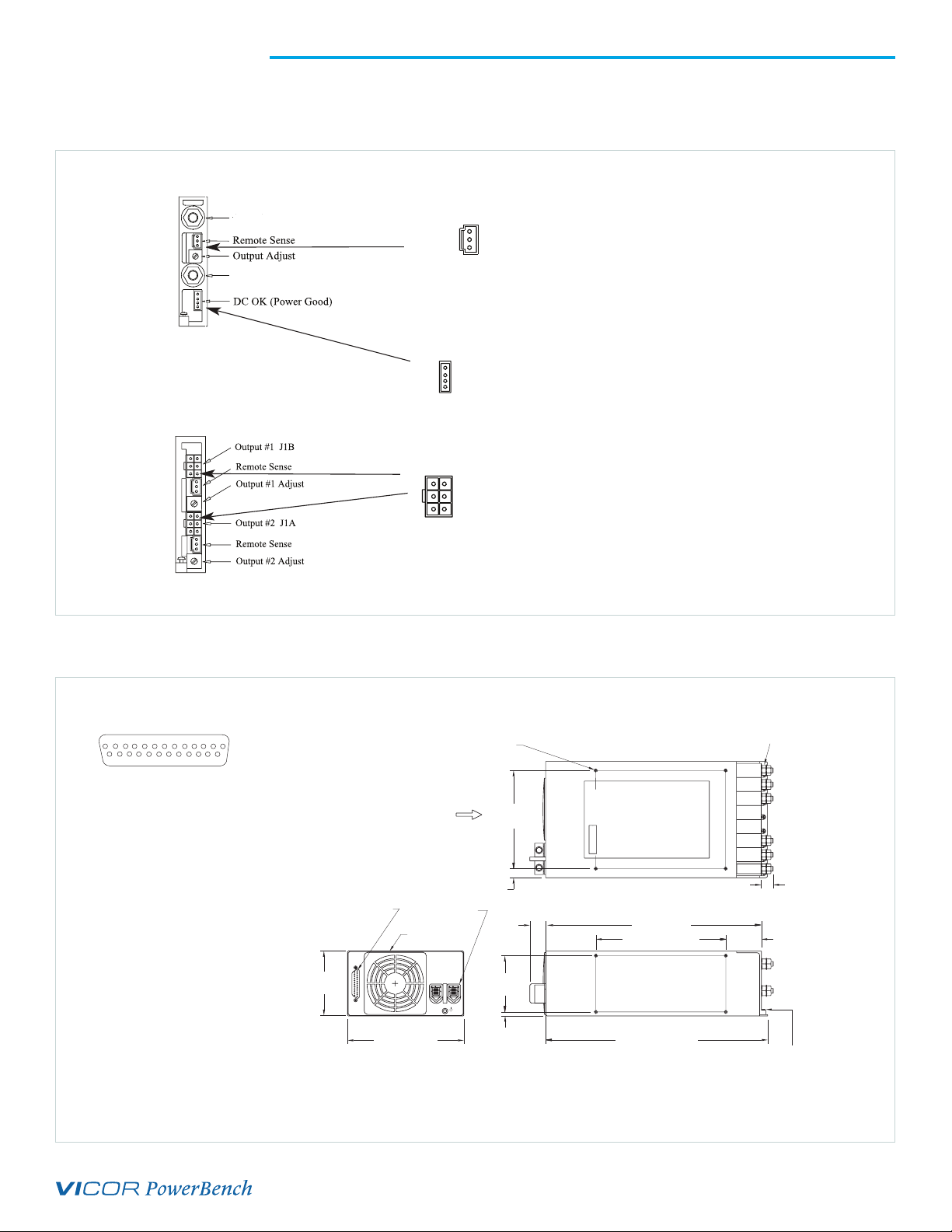
+
_
VI-200
Output Adjust
–VOUT
+VOUT
DC OK (Power Good)
VI-J00
Remote Sense
Output Adjust
–VOUT
+VOUT
DC OK (Power Good)
Remote Sense
Output #2 Adjust
Output #2
Output #1
Remote Sense
Output #1 Adjust
VI-J00VI-J00
VI-J00 RAM
Remote Sense
Output Adjust
–VOUT
+VOUT
DC OK (Power Good)
ModuPAC
JuniorPAC
DualPAC
RamPAC