UG:110 vicorpower.com Applications Engineering: 800 927.9474 Page 3
MegaPAC Do’s and Don’ts
nFor units without Autosense, do not leave ConverterPAC Sense lines open. Always
terminate them to their respective output locally or at the load. Use twisted pair 22-24
AWG wire. If ConverterPAC has Autosense, no local sense connection is required. See
Page 10 and Page 14 for more information on Autosense.
nIf needed, use Connector Kit # 19-130040 for the Mini MegaPAC.
nAlways fill all output slots of the MegaPAC. If a slot is not filled with a
ConverterPAC, it should be filled with an airblock. Airblocks are plastic assemblies
whose main function is to fill up an empty slot. Any airflow escape from an empty
slot significantly degrades thermal performance, and can result in overheating and
damage to the power supply.
nDo not unplug ConverterPACs while input power is applied. They are not
designed for hot-plug applications.
nDo not restrict airflow to the unit. The fan draws air into the unit and forces it out at
the output power terminals.
nSingle output ConverterPACs should NOT be paralleled directly together.
nFor power expansion, use booster ConverterPACs. Viewing the unit from the output
terminal side, always insert boosters to the right side of the driver. For booster arrays,
do not power up with bus bars removed.
nAlways ensure that output hex-nuts are properly torqued before applying
power to supply.
nDo not use boosters as independent outputs. Disconnecting bus bars will damage
booster ConverterPACs.
nRun the output (+/–) power cables next to each other to minimize inductance.
nWait 5 minutes aer shutting o power before inserting or removing ConverterPACs.
nThe MegaPACs do not have user-serviceable components. They must be returned to
the factory for repairs. Contact Customer Service for a RMA number before returning
the unit. Do not attempt to repair or modify the power supply in any manner other
than the exchange of ConverterPACs as described in this User Guide.
nInsert proper fault protection at power supply input terminals (i.e., a fuse).
nUse proper size wires to avoid overheating and excessive voltage drop.
nNever loosen the inner nut on a ConverterPAC. Verify output nuts are tight
before powering up.
nOutput voltages over 60 Vdc, whether from individual modules or series arrays, are
considered as hazardous secondary outputs under UL60950. Appropriate care must
be taken in design implementation of the supply.
nOnly use the regular length ConverterPACs in the Mini MegaPAC. One cannot use any
of the Extended Length ConverterPACS in the Mini MegaPAC. The ELs are only used
in the EL (Low Noise) products.
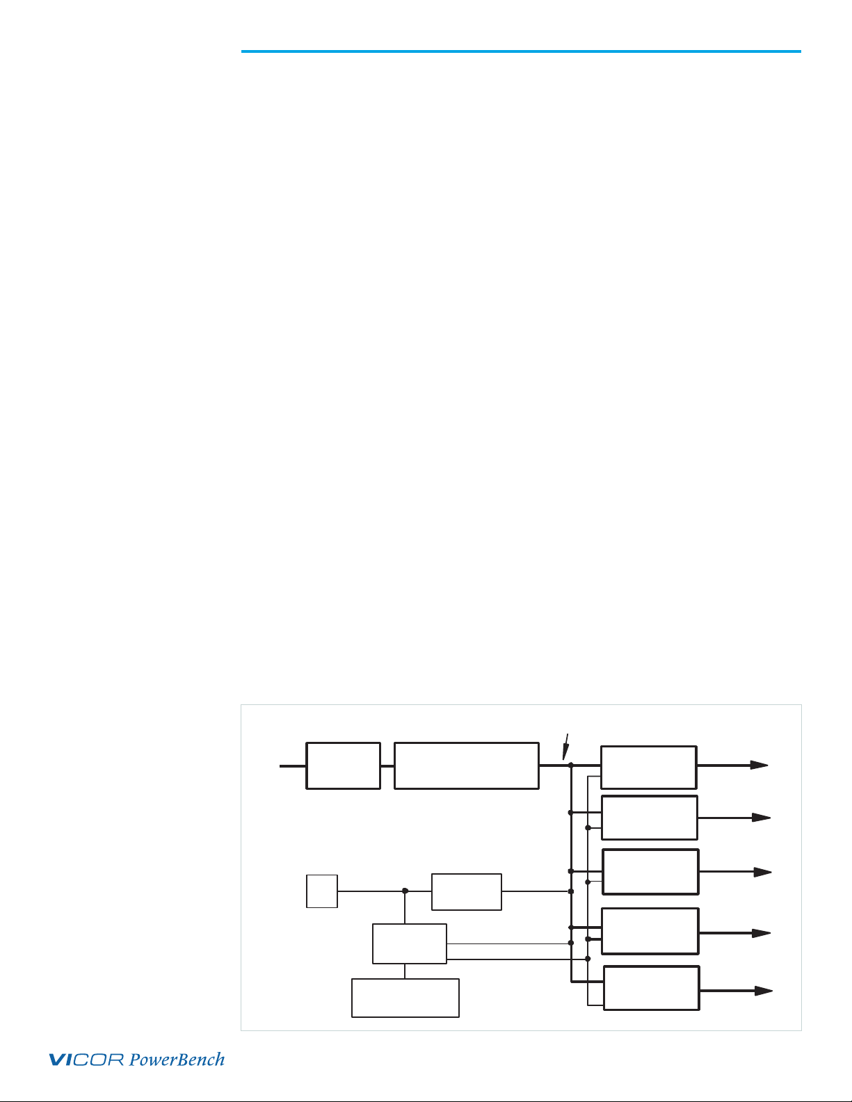
Technical Description
The Mini MegaPAC chassis consists of an o-line single phase AC front end, EMI filter,
cooling fan, customer interface and associated housekeeping circuits. Input AC mains
voltage (L1/N, L2 and GND) is applied to a terminal block. The input current is passed
through an EMI filter designed to meet EN55022 Class A and B. At start-up, inrush
current is limited by an NTC thermistor prior to being passed to the power rectifiers.
The power rectifiers and filter capacitors are arranged in a conventional full wave bridge