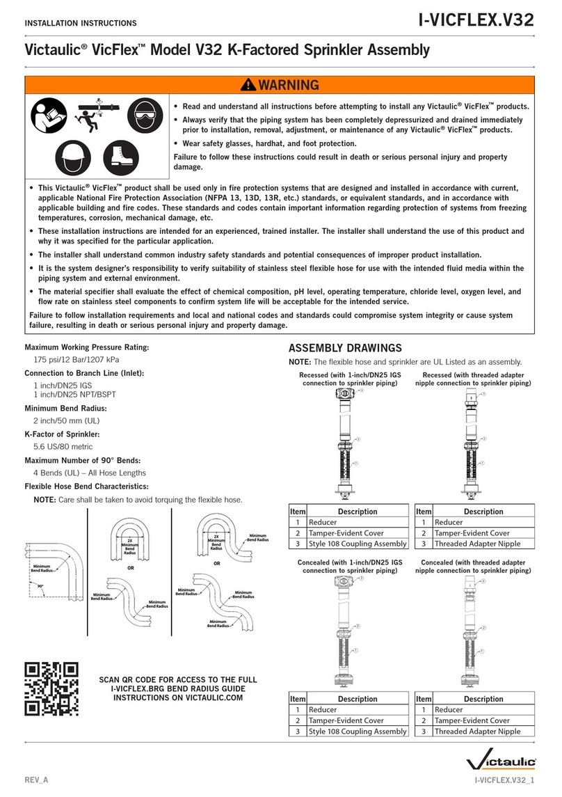
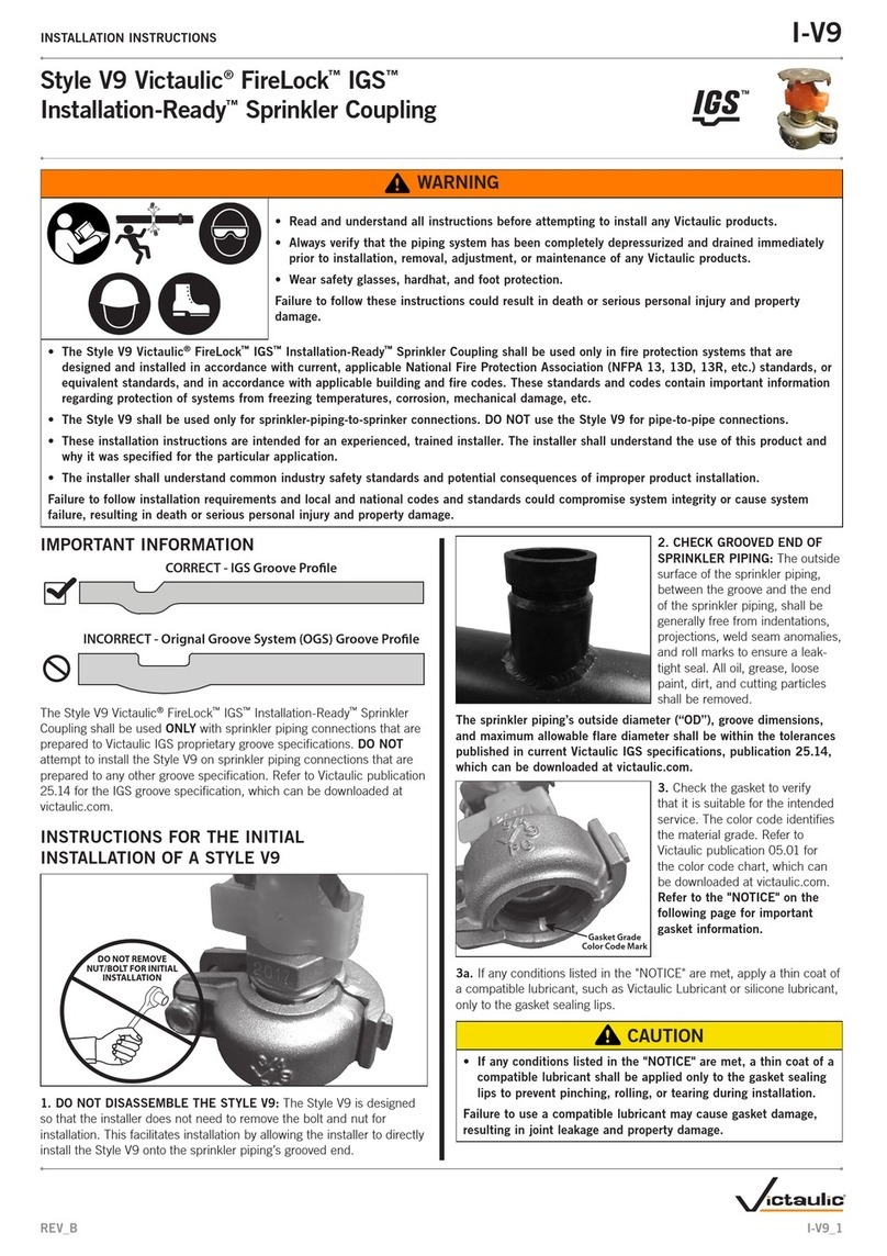
Victaulic FireLock Series User manual

victaulic.com
46.03 16398 Rev BUpdated 04/2021 © 2021 Victaulic Company. All rights reserved.
ALWAYS REFER TO ANY NOTIFICATIONS AT THE END OF THIS DOCUMENT REGARDING PRODUCT INSTALLATION, MAINTENANCE OR SUPPORT.
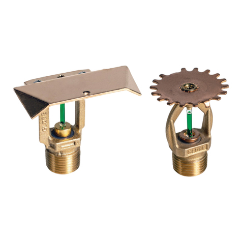
F L-S A / D S , V 5 6 21 FL-SA/GAP, V5623 FL-SA/BB, V8122 FL-SA/BB, V8123 FL-SA/BB, V8124
1.0 PRODUCT DESCRIPTION
SPECIFIC APPLICATION ATTIC SPRINKLERS
SIN V5621 V5623 V8122 V8123 V8124
ORIENTATION UPRIGHT UPRIGHT UPRIGHT UPRIGHT UPRIGHT
K-FACTOR1 5.6 Imp./8.1 S.I. 5.6 Imp./8.1 S.I. 8.0 Imp./11.5 S.I. 8.0 Imp./11.5 S.I. 8.0 Imp./11.5 S.I.
CONNECTION ½”NPT/15mm BSPT ½” NPT/15mm BSPT ¾" NPT/ 20mm BSPT ¾" NPT/ 20mm BSPT ¾" NPT/ 20mm BSPT
MAX. WORKING PRESSURE 175 psi (1200 kPa) 175 psi (1200 kPa) 175 psi (1200 kPa) 175 psi (1200 kPa) 175 psi (1200 kPa)
GLOBE RE-DESIGNATION GL5621 GL5623 GL8122 GL8123 GL8124
AVAILABLE WRENCHES
SPRINKLER V56 Open End V81 Open End
Upright ■ ■
Factory Hydrostatic Test: 100% @ 500 psi/3447 kPa/34 bar
Min. Operating Pressure: UL: 7 psi/48 kPa/.5 bar
Temperature Rating: See tables in section 2.0
1 For K-Factor when pressure is measured in bar, multiply S.I. units by 10.0.
2.0 CERTIFICATION/LISTINGS
Sprinkler Model SIN Nominal K Factor
Listing Agency/
Approved
Temperature Ratings Area of Use
Maximum
Roof Span Roof Pitch
Imperial ft
BB46 V8122 8.0 cULus 200°F/93°C RIDGE/GABLE 60 4:12 to less than 7:12
BB46/GAP V8122/V5623 8.0/5.6 cULus 200°F/93°C RIDGE/GABLE and
GAP at EAVE 84 4:12 to less than 7:12
BB79 V8123 8.0 cULus 200°F/93°C RIDGE/GABLE 60 7:12 to less than 10:12
BB79/GAP V8123/V5623 8.0/5.6 cULus 200°F/93°C RIDGE/GABLE and
GAP at EAVE 84 7:12 to less than 10:12
BB1012 V8124 8.0 cULus 200°F/93°C RIDGE/GABLE 60 10:12 to 12:12
BB1012/GAP V8124/V5623 8.0/5.6 cULus 200°F/93°C RIDGE/GABLE and
GAP at EAVE 84 10:12 to 12:12
GAP V5623 5.6 cULus 200°F/93°C EAVE/HIP N/A SEE LAYOUT CRITERIA
DS V5621 5.6 cULus 200°F/93°C HIP/SINGLE SLOPE N/A SEE LAYOUT CRITERIA
NOTES
• Listings and approval as of printing.
• Listed to be utilized per NFPA 13 in conformance with the New Technology and Equivalency Sections.
Victaulic®FireLock™Series FL-SA/GAP and FL-SA/BB
Specific Application Back-To-Back Attic Protection Scheme,
Quick Response Upright, K5.6 (8.0), K8.0 (11.5) 46.03
1

46.03 16398 Rev BUpdated 04/2021 © 2021 Victaulic Company. All rights reserved.
victaulic.com
3.0 SPECIFICATIONS – MATERIAL
Deflector: Bronze
Bulb Nominal Diameter: 3.0 mm
Load Screw: Brass
Pip Cap: Brass
Spring Seal Assembly: PTFE coated Beryllium nickel alloy
Frame: Brass
Lodgement Spring: Stainless steel
Installation Wrench: Ductile iron
Sprinkler Frame Finishes: Plain brass
NOTE
• For cabinets and other accessories refer to separate sheet.
4.0 DIMENSIONS
FL- SA / GA P FL- SA / DS
FL- SA / BB
2
victaulic.com

46.03 16398 Rev BUpdated 04/2021 © 2021 Victaulic Company. All rights reserved.
victaulic.com
5.0 PERFORMANCE
Sprinkler Selection
Identify Areas of the Attic
• Identify each space in your attic as a Gable area,
a Hip area or a Single Slope area. Refer to Figure
1 and Figure 5 through Figure 8 to choose the
appropriate use of sprinklers for your application.
Gable/Peak and Eave Areas
• The areas in which the Model FL-SA/BB can be
used are areas of the attic space where the roof
joists/ trusses run perpendicular to the ridgeline. In
the areas where the structure is perpendicular to
the ridgeline and the attic span is in both directions
of the ridgeline the Model FL-SA/BB shall be used.
In each of the areas being protected with the Model
FL-SA/BB sprinklers, identify the pitch/slope of the
roof in that area. Ensure that the correct Model
FL-SA/BB is chosen from the Table 1 based on the
pitch/slope.
• The span must be identified in the area being
protected by the Model FL-SA/BB. If the total span
of the attic is over 60 ft, a row of Model FL-SA/
GAP sprinklers must be located near the eave in
accordance with Figure 5 Option 2 and the layout
rules must be in accordance with Figure 9 and
Figure 10.
Single Slope Areas
• Single Slope areas are similar to the Gable/ Peak
areas, except a vertical wall or obstruction impeade
the flow of hot gasses to the apex or is located
directly at the apex of the attic space. When the hot
gasses hit a vertical obstruction the gasses keep
much of their velocity and tend to travel along the
ridgeline. In a true gable with an apex and sloped
ceiling on both sides, the hot gasses tend to run up
one side of the gable roof and partly down the other
section. This decreases the velocity of the gasses
running along the gable section. Ensure the spacing
rules are followed in accordance with Figure 11.
Under-Hip Areas
• With Hip areas the important features to identify in
the under-hip areas are the structurial members. It
is important to identify if the structural members run
parallel to the slope or perpendicular to the slope
("Step Down" trusses). If the structural members
run parallel to the slope, use Figure 13 or Figure 14.
If the structural members are "Step Down" trusses
framed into "Jack" trusses use Figure 12.
Adjacent-Hip Areas
• In the Ajdacent-HIP areas, either the Model FL-SA/
GAP or the Model FL-SA/DS sprinklers can be used.
If using Model FL-SA/DS refer to Figure 15 and if
using Model FL-SA/GAP refer to Figure 16.
TABLE 1: SPRINKLER SELECTION CRITERIA
SPRINKLER MODEL SIN AREA OF USE K FACTOR SPAN ROOF PITCH
BB46 V8122 RIDGE/GABLE 8 MAX 60 ft 4:12 to less than 7:12
BB46/GAP V8122/ V5623 RIDGE/GABLE and at EAVE 8.0/5.6 MAX 84 ft 4:12 to less than 7:12
BB79 V8123 RIDGE/GABLE 8 MAX 60 ft 7:12 to less than 10:12
BB79/GAP V8123/ V5623 RIDGE/GABLE and at EAVE 8.0/5.6 MAX 84 ft 7:12 to less than 10:12
BB1012 V8124 RIDGE/GABLE 8 MAX 60 ft 10:12 to 12:12
BB1012/GAP V8124/ V5623 RIDGE/GABLE and at EAVE 8.0/5.6 MAX 84 ft 10:12 to 12:12
GAP V5623 EAVE/HIP 5.6 NA SEE LAYOUT CRITERIA
DS V5621 HIP/SINGLE SLOPE 5.6 NA SEE LAYOUT CRITERIA
FIGURE 4A FIGURE 4B
FIGURE 4: SPAN MEASUREMENT/SPRINKLER
SPACING LOCATIONS
3
victaulic.com
46.03 16398 Rev BUpdated 04/2021 © 2021 Victaulic Company. All rights reserved.
victaulic.com
5.0 PERFORMANCE (CONTINUED)
Sprinkler Selection
Gable Style Roof Option 1:
FL-SA/BB Sprinklers Only at Gable/Peak
• When utilizing this option, Model FL-SA/BB sprinklers
are used to protect the entire width of the attic space.
The span of the attic is measured along the floor (or
ceiling of floor below) of the attic space from the peak
to the intersection of the top chord and bottom chord
of the roof trusses. See Figure 5a and Figure 5b.
The span is twice the longer of the two measured
half spans.
• The maximum span that can be protected by a single
line of FL-SA/BB sprinklers at the peak is 60 ft.
• See minimum required flow rates and pressures for
spans up to 40 ft. and spans over 40 ft. and up to
60 ft. is shown in Table 2 of this data sheet.
• See Figure 9 for detailed layout criteria.
TRUSS MEMBERS MUST BE
PARALLEL WITH DIRECTION
OF THROW OF FL-SA/BB
SPRINKLERS
FIGURE 5A
Gable Style Roof Option 2:
FL-SA/BB Sprinklers And FL-SA/GAP Sprinklers Adjacent
• This option utilizes the FL-SA/BB sprinklers at the
Gable/Peak and FL-SA/GAP sprinklers at the eave
areas. With this option, a maximum total span of
84 ft. can be achieved. The FL-SA/BB may cover a
maximum horizontal span of 60 ft. as stated in
Option 1 above. GLSS/ GAP sprinklers may be used
in conjunction with the FL-SA/BB sprinklers to achieve
up to an additional 12 ft. measured horizontally to each
eave. It should be noted that the "zone of coverage"
for the "GAP" sprinklers is only measured from the
centerline of the sprinkler to the eave. No credit for
coverage "upslope" can be assumed.
• See Figure 9 and Figure 10 for detailed layout criteria.
TRUSS MEMBERS MUST BE
PARALLEL WITH DIRECTION
OF THROW OF FL-SA/BB
SPRINKLERS
FIGURE 5B
FIGURE 5: PROTECTION OPTIONS
FL-SA/BB
FL-SA/GAP
4
victaulic.com

46.03 16398 Rev BUpdated 04/2021 © 2021 Victaulic Company. All rights reserved.
victaulic.com
5.0 PERFORMANCE (CONTINUED)
Sprinkler Selection
Single Slope Roof Option 1:
FL-SA/DS Sprinklers at the Highpoint Only
• When utilizing this option, Model FL-SA/DS sprinklers
are used to protect the entire width of the attic space
from the eave to the vertical barrier of the single slope.
The span of the attic is measured along the floor (or
ceiling of floor below) of the attic space from the
peak/vertical barrier to the intersection of the top
chord and bottom chord of the roof trusses. See
Figure 4a and Figure 4b.
• The maximum span that can be protected by a single
line of FL-SA/DS sprinklers at the peak is 16 ft or 30 ft
(measured horizontally from the sprinkler to eave).
• See Figure 11A and Figure 11B for detailed sprinkler
layout criteria.
Single Slope Roof Option 2:
FL-SA/DS Sprinklers at the Highpoint and Downslope
• When utilizing this option, Model FL-SA/DS sprinklers
are used to protect the entire width of the attic space
from the eave to the vertical barrier of the single
slope. The span of the attic is measured along the
floor (or ceiling of floor below) of the attic space
from the peak to the intersection of the top chord
and bottom chord of the roof trusses. See Figure 4a
and Figure 4b.
• The maximum span that can be protected by two
lines of FL-SA/DS sprinklers at the peak is 32 ft +
(depending on sprinkler placement).
• See Figure 11A and Figure 11C for detailed sprinkler
layout criteria.
FIGURE 6: SINGLE SLOPE PROTECTION OPTIONS
= Model Gap
= Model DS
5
victaulic.com

46.03 16398 Rev BUpdated 04/2021 © 2021 Victaulic Company. All rights reserved.
victaulic.com
5.0 PERFORMANCE (CONTINUED)
Sprinkler Selection
Under-Hip Layout Option 1:
Under-Hip Layout Option FL-SA/GAP Sprinklers Only
• When utilizing this option, Model FL-SA/GAP
sprinklers are used to protect the entire area
between the hip rafters. This option may be used
when the framing under the hip roof consists of
stepdown hip trusses running perpendicular to the
slope in conjuction with jack trusses near the eave.
• See Figure 12 for detailed layout criteria.
Under-Hip Layout Option 2:
Under-Hip Layout Option Using FL-SA/GAP Sprinklers or
Using FL-SA/DS Sprinklers
• When the framing runs parallel to the slope of the
hip, forming a 90 degree intersection at the hip
rafter, either Model FL-SA/DS in accordance with
Figure 13 or Model FL-SA/GAP in accordance with
Figure 14 may be utilized.
FIGURE 7: UNDER-HIP PROTECTION OPTIONS
FL-SA/GAP
FL-SA/DS
6
victaulic.com

46.03 16398 Rev BUpdated 04/2021 © 2021 Victaulic Company. All rights reserved.
victaulic.com
5.0 PERFORMANCE (CONTINUED)
Sprinkler Selection
Adjacent Hip Layout Option 1:
FL-SA/DS Sprinklers Only
• When utilizing this option, Model FL-SA/DS sprinklers
are used to protect the section of the attic space
adjacent to the HIP area.
• See Figure 15 for detailed layout criteria
Adjacent Hip Layout Option 2:
FL-SA/GAP Sprinklers Only
• When utilizing this option, Model FL-SA/GAP sprinklers
are used to protect the section of the attic space
adjacent to the HIP area.
• See Figure 16 for detailed layout criteria.
FIGURE 8: ADJACENT HIP PROTECTION OPTIONS
FL-SA/GAP
FL-SA/DS
7
victaulic.com

46.03 16398 Rev BUpdated 04/2021 © 2021 Victaulic Company. All rights reserved.
victaulic.com
5.0 PERFORMANCE (CONTINUED)
Layout Criteria – Gable
Sprinkler Model
• F L- SA / BB
Flow Rate
• ≤ 40 ft. span: 24 gpm
• >40 ft. up to and including 60 ft. span 38 gpm
Distance Between Sprinklers Along Ridge
• Minimum 4 ft.
• Maximum 6 ft.
Deflector Distance Below Ceiling
• Minimum 16 in.
• Maximum 24 in.
Lateral Maximum Distance From Peak
• 6 in.
Distance From Hip Apex Or Wall
• Maximum 3 ft.
Installation
• When installed for Peak protection, the FL-SA/BB
Sprinkler has a zone of protection of 60 ft. wide (as
measured horizontally) across the ridgeline. The
maximum zone of protection on either side of the
ridgeline is 30 ft. (as measured horizontally). The
zone of protection along the ridgeline is 6 ft. per FL-
SA/BB sprinkler. (3 ft. to either side)
• When a FL-SA/BB sprinkler is installed under a
horizontal Ridge, the deflector is to be positioned
parallel with the floor/ceiling below. (Regardless of
allowed offset from directly below ridge)
• Maximum span for FL-SA/BB sprinkler to cover is 60
ft wide attic.
• Sprinklers must be installed with the frame arms
perpendicular to the trusses.
• A minimum of 6" must be kept from the sprinkler
and the lateral face of any truss. (see Figure 28).
• For obstruction criteria, see Obstruction section
within this data sheet.
• Minimum lateral distance from FL-SA/BB and FL-SA/
GAP is 6 ft.
• Minimum lateral distance from FL-SA/BB and FL-
SA/DS is 4 ft.
• When installed under a flat sloped ceiling
(noncombustible insulation filled joist channels)
maximum deflector to ceiling distance is measured
to the bottom of the insulation.
HYDRAULIC CALCULATIONS
• See Hydraulic Design Section
TRUSS MEMBERS MUST BE
PARALLEL WITH DIRECTION
OF THROW OF FL-SA/BB
SPRINKLERS
NOTE
• If a flat sloped ceiling is present
utilizing non combustible
insulation, the insulation must
completely fill the pockets
between the joists, and the
insulation must be secured in
place with metal wire netting or
equivalent. The metal wire
netting is intended to hold the
insulation in place should the
insulation become wetted by the
operation of the sprinkler. Attic
sprinklers have not been
evaluated for use with spray
foam insulation.
FIGURE 9: GABLE LAYOUT CRITERIA MODEL FL-SA/BB
8
victaulic.com

46.03 16398 Rev BUpdated 04/2021 © 2021 Victaulic Company. All rights reserved.
victaulic.com
5.0 PERFORMANCE (CONTINUED)
Layout Criteria – Eave
Sprinkler Model
• FL-S A / G A P
Flow Rate
• 20 gpm
Distance Between Sprinklers Perpendicular To Slope
• Minimum 6 ft
• Maximum 8 ft
Distance to Attic Eave
• Minimum 4 ft
• Maximum 12 ft
Minimum Distance From FL-SA/BB Sprinkler (Measured
Along The Slope)
• Minimum 21 ft (Located in Adjacent Channel)
Deflector Distance Below Ceiling
• Install with deflector below bottom of top chord 1"
minimum to 3" maximum.
Installation
• When installed for Eave protection, the FL-SA/GAP
Sprinkler has a zone of protection of 12 ft. in the
downslope direction to the eave (measured on the
horizontal) and 8 ft. wide (4 ft. laterally to either
side of the sprinkler). There is no zone of protection
allowance "upslope" of the FL-SA/GAP sprinklers
when used along eaves in conjunction with the FL-
SA/BB sprinklers upslope.
• Ensure that the sprinkler is installed with the
deflector parallel to the sloped roof above.
• Centerline of sprinkler must be a minimum of 6"
laterally from face of truss (See Figure 28).
• Must be offset at least one channel laterally from
any upslope sprinkler.
• Sprinklers must be installed with the frame arms
perpendicular to the roof slope.
• For obstruction criteria, see Obstruction section
within this data sheet.
• When installed under a flat sloped ceiling
(noncombustible insulation filled joist channels),
maximum deflector to ceiling distance is the same
as maximum distance below bottom of top chord.
Distance to be measured to bottom of insulation.
Hydraulic Calculations
• See Hydraulic Design Section
FL-SA/GAP SPRINKLERS MUST BE
OFFSET AT LEAST ONE CHANNEL
FROM FL-SA/BB SPRINKLERS
UPSLOPE
FIGURE 10: EAVE LAYOUT CRITERIA
NOTE
• If a flat sloped ceiling is present utilizing non combustible insulation, the insulation must completely fill the pockets between the joists, and the insulation
must be secured in place with metal wire netting or equivalent. The metal wire netting is intended to hold the insulation in place should the insulation
become wetted by the operation of the sprinkler. Attic sprinklers have not been evaluated for use with spray foam insulation.
FL-SA/BB
FL-SA/GAP
9
victaulic.com

46.03 16398 Rev BUpdated 04/2021 © 2021 Victaulic Company. All rights reserved.
victaulic.com
5.0 PERFORMANCE (CONTINUED)
Layout Criteria – Single Slope
Sprinkler Model
• F L- SA / D S
Slope
• 4:12 Up to and Including 12:12
Flow Rate
• 20 gpm
Deflector Distance Below Peak (See Figure 14A)
• Minimum 16 in.
• Maximum 24 in.
Deflector Distance Below Sloping Roof Deck (See Figure
14a)
• Install with deflector below bottom of top chord to a
maximum of 2 in.
Distance Between Sprinklers Perpendicular To The Slope
• Minimum 4 ft.
• Maximum 8 ft.
Maximum Allowed Sprinkler Throw (Measured
Horizontally)
• Downslope – 16 ft.
Minimum Distance Between Sprinklers Downslope of The
FL-SA/DS (Throw Direction)
• 15 ft. (as measured on the slope) INSTALLATION
• Ensure that the sprinkler deflector is installed with
the deflector parallel to the sloped roof above.
• Centerline of sprinkler must be a minimum of 6"
laterally from face of truss. See Figure 28.
• When two rows of FL-SA/DS sprinklers are utilized,
the adjacent rows of sprinklers must be offset at
least one channel laterally from each other.
• Sprinklers must be installed with the frame arms
perpendicular to the roof slope. See Figure 35.
• For obstruction criteria, see Obstruction section
within this data sheet.
• When installed under a flat sloped ceiling
(noncombustible insulation filled joist channels),
maximum deflector to ceiling distance is the same
as maximum distance below bottom of top chord.
Distanceto be measured to bottom of Insulation.
Hydraulic Calculations
• See Hydraulic Design Section
NOTE
• If a flat sloped ceiling is present utilizing non combustible insulation, the
insulation must completely fill the pockets between the joists, and the
insulation must be secured in place with metal wire netting or equivalent.
The metal wire netting is intended to hold the insulation in place should
the insulation become wetted by the operation of the sprinkler. Attic
sprinklers have not been evaluated for use with spray foam insulation.
FIGURE 11A: SECTION VIEW DS SPRINKLER & DEFLECTOR PLACEMENT AT PEAK
FL-SA/DS
FIGURE 11B: 1 ROW DS SPRINKLER (HIP SHOWN AT CORNER) FIGURE 11C: 2 ROW DS SPRINKLER (HIP SHOWN AT CORNER)
FIGURE 11: SINGLE SLOPE SPACING CRITERIA
10
victaulic.com

46.03 16398 Rev BUpdated 04/2021 © 2021 Victaulic Company. All rights reserved.
victaulic.com
5.0 PERFORMANCE (CONTINUED)
Layout Criteria – Under-Hip Sprinkler: Hip Truss/Jack Truss Construction
Sprinkler Model
• FL-S A / G A P
Flow Rate
• 20 gpm
Distance Between Sprinklers
First Row From Eave (Measured Horizontally)
• Minimum 6 ft
• Maximum 8 ft
Distance Between Sprinklers
All Other Rows Upslope (Measured Horizontally)
• Minimum 6 ft
• Maximum 12 ft
Distance From Eave To First Row
(measured horizontally)
• Minimum 5 ft
• Maximum 12 ft
Distance Between Rows (Measured Horizontally)
• Minimum 6 ft
• Maximum 10 ft
Deflector Distance Below Ceiling
• Install with deflector below bottom of top chord 1"
minimum to 3" maximum.
Sprinkler at Apex
• A FL-SA/GAP Sprinkler must be installed between 1
ft. to 5 ft. down from the intersection of the ridgeline
and hip lines (Apex)
Sprinklers Adjacent to Hip Line
• All FL-SA/GAP Sprinklers directly adjacent to hip
line shall be 1 ft. to 3 ft. from hip line (as measured
perpendicular to hip line)
Installation
• Ensure that the sprinkler is installed with the
deflector parallel to the sloped roof above.
• Sprinklers must be installed with the frame arms
perpendicular to the roof slope (see Figure 35).
• When installed under a flat sloped ceiling
(noncombustible insulation filled joist channels),
maximum deflector to ceiling distance is the same
as maximum distance below bottom of top chord.
Distance to be measured to bottom of Insulation.
Hydraulic Calculations
• See Hydraulic Design Section
FIGURE 12A: HIP LAYOUT CRITERIA WHEN FIRST ROW OF SPRINKLERS
PLACED "WITHIN" JACK TRUSSES
FIGURE 12B: HIP LAYOUT CRITERIA WHEN FIRST ROW OF SPRINKLERS
PLACED "BEYOND" JACK TRUSSES
FIGURE 12: HIP LAYOUT CRITERIA – HIP TRUSS/JACK TRUSS CONSTRUCTION
NOTE
• If a flat sloped ceiling is present utilizing non combustible insulation, the insulation must completely fill the pockets between the joists, and the insulation must
be secured in place with metal wire netting or equivalent. The metal wire netting is intended to hold the insulation in place should the insulation become
wetted by the operation of the sprinkler. Attic sprinklers have not been evaluated for use with spray foam insulation.
11
victaulic.com

46.03 16398 Rev BUpdated 04/2021 © 2021 Victaulic Company. All rights reserved.
victaulic.com
5.0 PERFORMANCE (CONTINUED)
Sprinkler Layout – Under-Hip Criteria: Framing Members Parallel To Roof Slope
Sprinkler Model
• FL-SA/DS (FL-SA/GAP @ apex)
Flow Rate
• 20 gpm
Distance Between Sprinklers
• Minimum 6 ft
• Maximum 8 ft
Distance From Eave to First Row (measured horizontally)
• Minimum 5 ft
• Maximum 20 ft
Deflector Distance Below Ceiling
• Install with deflector below bottom of top chord 1"
minimum to 4" maximum.
Sprinkler at Apex
• A FL-SA/GAP Sprinkler must be installed between 1
ft. to 5 ft. down from the intersection of the ridgeline
and hip lines (Apex)
Sprinklers Adjacent To Hip Line
• All FL-SA/GAP Sprinklers directly adjacent to hip
line shall be 1 ft. to 3 ft. from hip line (as measured
perpendicular to hip line)
Installation
• Ensure that the sprinkler is installed with the
deflector parallel to the sloped roof above Sprinklers
must be installed with the frame arms perpendicular
to the roof slope (see Figure 4).
• For obstruction criteria, see Obstruction section
within this data sheet.
• When installed under a flat sloped ceiling
(noncombustible insulation filled joist channels),
maximum deflector to ceiling distance is the same
as maximum distance below bottom of top chord.
Distance to be measured to bottom of Insulation.
Hydraulic Calculations
• See Hydraulic Design Section
FIGURE 13: UNDER-HIP LAYOUT CRITERIA
FRAMING MEMBERS PARALLEL TO ROOF SLOPE USING FL-SA/DS
NOTE
• If a flat sloped ceiling is present utilizing non combustible insulation, the insulation must completely fill the pockets
between the joists, and the insulation must be secured in place with metal wire netting or equivalent. The metal
wire netting is intended to hold the insulation in place should the insulation become wetted by the operation of the
sprinkler. Attic sprinklers have not been evaluated for use with spray foam insulation.
MODEL FL-SA/DS
12
victaulic.com

46.03 16398 Rev BUpdated 04/2021 © 2021 Victaulic Company. All rights reserved.
victaulic.com
5.0 PERFORMANCE (CONTINUED)
Sprinkler Layout – Under-Hip Criteria: Framing Members Parallel To Roof Slope
Sprinkler Model
• FL-S A / G A P
Flow Rate
• 20 gpm
Distance From Eave to First Row (measured horizontally)
• Minimum 5 ft
• Maximum 12 ft
Maximum Distance Between Sprinklers
• See Figure 12
Deflector Distance Below Ceiling
• Install with deflector below bottom of top chord 1"
minimum to 3" maximum
Sprinkler at Apex
• A FL-SA/GAP Sprinkler must be installed between 1
ft. to 5 ft. down from the intersection of the ridgeline
and hip lines (Apex)
Sprinklers Adjacent To Hip Line
• All FL-SA/GAP Sprinklers directly adjacent to hip
line shall be 1 ft. to 3 ft. from hip line (as measured
perpendicular to hip line) Installation
• Ensure that the sprinkler is installed with the
deflector parallel to the sloped roof above Sprinklers
must be installed with the frame arms perpendicular
to the roof slope.
• For obstruction criteria, see Obstruction section
within this data sheet.
Hydraulic Calculations
• See Hydraulic Design Section
FIGURE 14: UNDER-HIP LAYOUT CRITERIA
FRAMING MEMBERS PARALLEL TO ROOF SLOPE USING FL-SA/GAP
NOTE
• If a flat sloped ceiling is present utilizing non combustible insulation, the insulation must completely fill the pockets
between the joists, and the insulation must be secured in place with metal wire netting or equivalent. The metal
wire netting is intended to hold the insulation in place should the insulation become wetted by the operation of the
sprinkler. Attic sprinklers have not been evaluated for use with spray foam insulation.
FL-SA/GAP
13
victaulic.com

46.03 16398 Rev BUpdated 04/2021 © 2021 Victaulic Company. All rights reserved.
victaulic.com
5.0 PERFORMANCE (CONTINUED)
Sprinkler Layout – Adjacent Hip Criteria
Sprinkler Model
F L- SA / D S
Flow Rate
• 20 gpm
Distance Between Sprinklers
• Minimum 6 ft
• Maximum 8 ft
Distance From Eave To First Row (measured horizontally)
• Minimum 5 ft
• Maximum 20 ft
Deflector Distance Below Ceiling
• Install with deflector below bottom of top chord 1"
minimum to 4" maximum.
Sprinklers Adjacent To Hip Line
• All FL-SA/GAP Sprinklers directly adjacent to hip
line shall be 1 ft. to 3 ft. from hip line (as measured
perpendicular to hip line)
Installation
• Ensure that the sprinkler is installed with the
deflector parallel to the sloped roof above
• Sprinklers must be installed with the frame arms
perpendicular to the roof slope (see Figure 35).
• For obstruction criteria, see Obstruction section
within this data sheet.
Hydraulic Calculations
• See Hydraulic Design Section
FIGURE 15: ADJACENT HIP LAYOUT CRITERIA USING FL-SA/DS SPRINKLERS
NOTE
• If a flat sloped ceiling is present utilizing non combustible insulation, the insulation must completely fill the pockets
between the joists, and the insulation must be secured in place with metal wire netting or equivalent. The metal
wire netting is intended to hold the insulation in place should the insulation become wetted by the operation of the
sprinkler. Attic sprinklers have not been evaluated for use with spray foam insulation.
MODEL FL-SA/DS
14
victaulic.com

46.03 16398 Rev BUpdated 04/2021 © 2021 Victaulic Company. All rights reserved.
victaulic.com
5.0 PERFORMANCE (CONTINUED)
Adjacent Hip Sprinkler Layout Criteria
Sprinkler Model
F L- SA / D S
Flow Rate
• 20 gpm
Distance Between Sprinklers
• Minimum 6 ft
• Maximum 8 ft
Distance From Eave To First Row (measured horizontally)
• Minimum 5 ft
• Maximum 20 ft
Deflector Distance Below Ceiling
• Install with deflector below bottom of top chord 1"
minimum to 3" maximum.
Sprinklers Adjacent To Hip Line
• All FL-SA/GAP Sprinklers directly adjacent to hip
line shall be 1 ft. to 3 ft. from hip line (as measured
perpendicular to hip line)
Installation
• Ensure that the sprinkler is installed with the
deflector parallel to the sloped roof above
• Sprinklers must be installed with the frame arms
perpendicular to the roof slope (see Figure 35).
• For obstruction criteria, see Obstruction section
within this data sheet.
Hydraulic Calculations
• See Hydraulic Design Section
FIGURE 16: ADJACENT HIP LAYOUT CRITERIA USING FL-SA/GAP SPRINKLERS
NOTE
• If a flat sloped ceiling is present utilizing non combustible insulation, the insulation must completely fill the pockets
between the joists, and the insulation must be secured in place with metal wire netting or equivalent. The metal
wire netting is intended to hold the insulation in place should the insulation become wetted by the operation of the
sprinkler. Attic sprinklers have not been evaluated for use with spray foam insulation.
FL-SA/GAP
15
victaulic.com

46.03 16398 Rev BUpdated 04/2021 © 2021 Victaulic Company. All rights reserved.
victaulic.com
5.0 PERFORMANCE (CONTINUED)
Dormer Protection Criteria
Dormers Built Entirely Over (on top) of Main Roof Sheathing – 4 Sprinklers or Less
• FL-SA/BB, FL-SA/GAP, and FL-SA/DS sprinklers allowed (CPVC allowance applies for wet systems only)
• Standard Spray Sprinklers allowed
Dormers Built Entirely Over (on top) of Main Roof Sheathing – More than 4 Sprinklers
• FL-SA/BB, FL-SA/GAP, and FL-SA/DS Sprinklers allowed- Protection scheme utilized shall be in accordance with
this document
• Standard Spray Sprinklers allowed for any slope
Dormers Open to Attic Space Below – 4 Sprinklers or Less
• FL-SA/BB, FL-SA/GAP, and FL-SA/DS Sprinklers allowed (CPVC allowance applies for wet systems only)
• Standard Spray Sprinklers allowed
Dormers Open to Attic Space Below – More than 4 Sprinklers
• FL-SA/BB, FL-SA/GAP, and FL-SA/DS Sprinklers allowed. Protection scheme utilized, shall be in accordance with
this document
• Standard Spray Sprinklers allowed but required to calculate Attic in accordance with NFPA 13 (i.e. 2535 sq. ft.
for Dry Systems)
FIGURE 17A: DORMER OPEN TO ATTIC SPACE FIGURE 17B: DORMER ENTIRELY OVER MAIN ROOF SHEATHING
FIGURE 17: DORMERS SECTION VIEW
NOTE
• If a flat sloped ceiling is present utilizing non combustible insulation, the insulation must completely fill the pockets between the joists, and the insulation must
be secured in place with metal wire netting or equivalent. The metal wire netting is intended to hold the insulation in place should the insulation become
wetted by the operation of the sprinkler. Attic sprinklers have not been evaluated for use with spray foam insulation.
16
victaulic.com

46.03 16398 Rev BUpdated 04/2021 © 2021 Victaulic Company. All rights reserved.
victaulic.com
5.0 PERFORMANCE (CONTINUED)
Hydraulic Design
The Specific Application Attic protection scheme shall be hydraulically calculated in accordance with the following
guidelines. These calculation guidelines are applicable only to the special Attic Protection scheme utilizing FL-SA/BB,
FL-SA/GAP, and FL-SA/DS sprinklers. These requirements are based on special full scale fire testing and in no way
should be utilized when designing other than these specially Listed and tested sprinklers for use in sloped com-
bustible attic structures. As with Hydraulic Calculations performed in accordance with NFPA 13, multiple areas of
piping may need to be investigated and multiple calculations performed should it not be readily obvious of the
hydraulically most demanding area due to non-typical pipe layout.
• FL-SA/BB Minimum Sprinkler Demand- The minimum required flow and pressure is shown below in Table 2. The
minimum sprinkler demand is dependent on the span that the FL-SA/BB is covering.
• FL-SA/GAP and FL-SA/DS Minimum Sprinkler Demand- The minimum required sprinkler demand for the FL-SA/
GAP, and FL-SA/DS is always 20 gpm and 12.8 psi.
TABLE 2: HYDRAULIC CRITERIA
Sprinkler Model Sin K Factor Span Roof Pitch Minimum Flow Rate Minimum Pressure
gpm psi
BB46 V8122 8.0 >40 ft to ≤60 ft 4:12 to less than 7:12 38 22.6
BB46 V8122 8.0 ≤40 ft 4:12 to less than 7:12 24 9
BB79 V8123 8.0 >40 ft to ≤60 ft 7:12 to less than 10:12 38 22.6
BB79 V8123 8.0 ≤40 ft 7:12 to less than 10:12 24 9
BB1012 V8124 8.0 >40 ft to ≤60 ft 10:12 to 12:12 38 22.6
BB1012 V8124 8.0 ≤40 ft 10:12 to 12:12 24 9
GAP V5623 5.6 NA SEE LAYOUT CRITERIA 20 12.8
DS V5621 5.6 NA SEE LAYOUT CRITERIA 20 12.8
17
victaulic.com

46.03 16398 Rev BUpdated 04/2021 © 2021 Victaulic Company. All rights reserved.
victaulic.com
5.0 PERFORMANCE (CONTINUED)
Hydraulic Criteria FL-SA/BB Only or FL-SA/BB with FL-SA/GAP and/or FL-SA/DS for Wet and Dry Systems
Perform the following calculations:
Calculation #1:
• Calculate the most hydraulically demanding sprinklers consisting of 5 FL-SA/BB and up to a maximum of 2 FL-
SA/ GAP or FL-SA/DS sprinklers (if applicable) for wet systems or 7 FL-SA/BB and up to a maximum of 2 FL-SA/
GAP or FL-SA/DS sprinklers (if applicable) for dry systems. See Figure 18 for wet systems and Figure 19 for dry
systems. See Table 2 for minimum flow and pressure requirements for the specific span, pitch and sprinkler type.
Calculation #2:
• If a HIP is present, find the appropriate Figure in the Hydraulic Criteria Section and perform the required
calculations.
NOTE
• If additional sprinklers are required beyond an obstruction, calculate up to 2 additional sprinklers beyond the obstruction.
HIP may or may not be present HIP may or may not be present
FIGURE 18:
HYDRAULIC CRITERIA FL-SA/BB AND/OR FL-SA/GAP AND/OR FL-SA/DS WET SYSTEM
FIGURE 19:
HYDRAULIC CRITERIA FL-SA/BB AND/OR FL-SA/GAP AND/OR FL-SA/DS DRY SYSTEMS
NOTE
• If a flat sloped ceiling is present utilizing non combustible insulation, the insulation must completely fill the pockets between the joists, and the insulation must
be secured in place with metal wire netting or equivalent. The metal wire netting is intended to hold the insulation in place should the insulation become
wetted by the operation of the sprinkler. Attic sprinklers have not been evaluated for use with spray foam insulation.
18
victaulic.com

46.03 16398 Rev BUpdated 04/2021 © 2021 Victaulic Company. All rights reserved.
victaulic.com
5.0 PERFORMANCE (CONTINUED)
Hydraulic Criteria For Hip With Hip Truss/Jack Truss Construction – Wet System Only
When a Hip is included in the design of the attic, there are three calculations required. One calculation for the “Ridge/
Hip Transition” area. The second and third calculations determine the pipe sizing for the Hip area itself. For the
purposes of these hydraulic calculations the Hip is broken into two areas; the “Lower Hip” area; and the “Upper Hip”
area. See above Figure.
Hip Calculation (Hip Truss/Jack Truss Construction) – Wet System
Calculation #1 – Lower Hip Area
• Calculate up to the 7 most demanding contiguous sprinklers along the eave. This may include sprinklers on both
sides of the hip line as shown. See Figure 20A and Figure 20B.
• Minimum sprinkler flow rate is 20 gpm per sprinkler.
Calculation #2 – Upper Hip Area
If there are 4 sprinklers or less in the shaded area (Figure 20A):
• Calculate up to the 7 most demanding contiguous sprinklers in the "Upper Hip" area. This may include sprinklers
on both sides of the hip line as shown.
• Minimum sprinkler flow rate is 20 gpm per sprinkler.
If there are more than 4 sprinklers in the shaded area (Figure 20B):
• Calculate the hydraulically most demanding 75% of the total number of sprinklers located within the "Upper Hip"
area, rounding up to the nearest sprinkler. (Minimum number of sprinklers to be calculated is 7)
• Minimum sprinkler flow rate is 20 gpm per sprinkler.
• Example shown in FIGURE 20B results in 12 sprinklers to be calculated. (18 x 0.75 = 12)
FIGURE 20A FIGURE 20B
FIGURE 20: HYDRAULIC CALCULATIONS REQUIRED FOR HIP – WET SYSTEM (HIP TRUSS/JACK TRUSS CONSTRUCTION)
FL-SA/GAP
FL-SA/DS
19
victaulic.com

46.03 16398 Rev BUpdated 04/2021 © 2021 Victaulic Company. All rights reserved.
victaulic.com
5.0 PERFORMANCE (CONTINUED)
Hydraulic Criteria For Hip With Hip Truss/Jack Truss Construction – Dry System Only
Calculation #1 – Lower Hip Area
• Calculate the 8 most demanding contiguous sprinklers along the eave. This may include sprinklers on both sides
of the hip line as shown. See Figure 21A.
• Minimum sprinkler flow rate is 20 gpm per sprinkler.
Calculation #2 – Upper Hip Area
If there are 4 sprinklers or less in the shaded area (Figure 21A):
• Calculate up to the 8 most demanding contiguous sprinklers in the "Upper Hip" area. This may include sprinklers
on both sides of the hip line as shown. See Figure 18B.
• Minimum sprinkler flow rate is 20 gpm per sprinkler.
If there are more than 4 sprinklers in the shaded area (Figure 21B):
• Calculate all sprinklers in the "Upper Hip" area.
• Minimum sprinkler flow rate is 20 gpm per sprinkler.
FIGURE 21A FIGURE 21B
FL-SA/GAP
FL-SA/DS
FIGURE 21: HYDRAULIC CALCULATIONS REQUIRED FOR HIP – DRY SYSTEM (HIP TRUSS/JACK TRUSS CONSTRUCTION)
(Examples shown in these figures are for reference only.
Actual sprinklers selected based on piping configuration which results in the most demanding hydraulic demand.)
20
victaulic.com
Other manuals for FireLock Series
1
This manual suits for next models
8
Table of contents
Other Victaulic Irrigation System manuals

Victaulic
Victaulic FireLock I-800 User manual

Victaulic
Victaulic VS1 Series User manual

Victaulic
Victaulic VicFlex V32 User manual

Victaulic
Victaulic V9 FireLock IGS User manual

Victaulic
Victaulic VicFlex I-VICFLEX.AQC-U User manual

Victaulic
Victaulic VicFlex VS1 User manual

Victaulic
Victaulic FireLock I-800 User manual

Victaulic
Victaulic VicFlex AH1 User manual

Victaulic
Victaulic FireLock Series User manual

Victaulic
Victaulic VicFlex Style AB6 User manual