IMPORTANT INSTALLATION INFORMATION
• Victaulic®VicFlex™Style VS1 Dry Sprinklers shall be installed
according to current, applicable National Fire Protection
Association (NFPA 13, 13D, 13R, etc.) standards or equivalent
standards. Style VS1 Dry Sprinklers are intended to be installed
in wet, dry, or preaction actuated systems. Deviations from these
standards or alterations to Style VS1 Dry Sprinklers will void any
Victaulic warranty and will impact system integrity. Installations
shall meet the provisions of the local authority having jurisdiction
and local codes, as applicable.
• Victaulic® VicFlex™Sprinkler Fittings shall not be intermixed with
other manufacturer’s flexible sprinkler products.
• Transport and store Style VS1 Dry Sprinklers in a cool, dry
environment in their original packaging.
• Refer to the specific Victaulic product submittal for applications
and listing information. Submittals can be downloaded at
victaulic.com.
• Size the piping system to provide the minimum operating pressure
of 7 psi/0.5 Bar/48 kPa.
• Per NFPA requirements, flush the system to remove foreign
material. Continue to flush the system until water runs clear.
• DO NOT install sprinkler system piping through heating ducts.
• DO NOT connect sprinkler system piping to domestic hot water
systems.
• DO NOT install Style VS1 Dry Sprinklers where they will be
exposed to temperatures that exceed the maximum ambient
temperature rating for the sprinkler and sprinkler fittings.
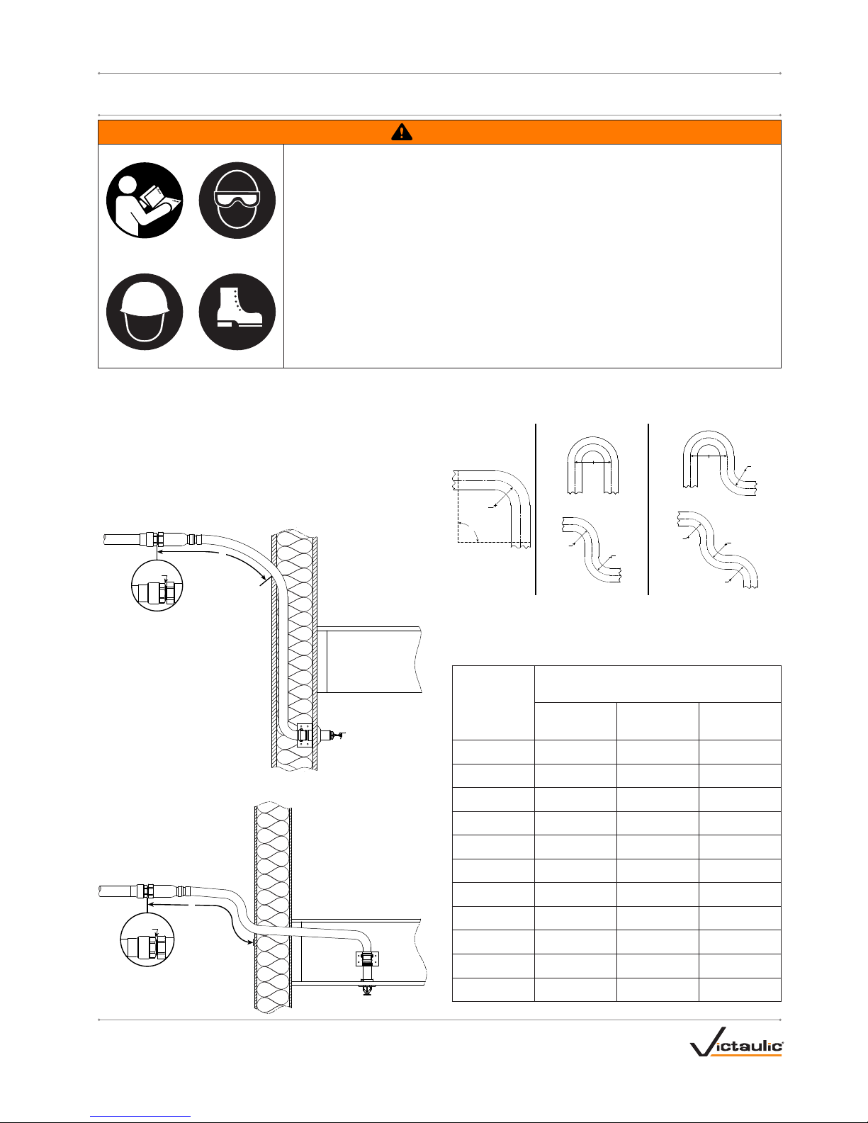
• Style VS1 Dry Sprinklers have limited flexibility* and are
intended only to be installed with bends not less than their
respective minimum bend radii. DO NOT install flexible hose in
a straight configuration.
• Protect wet piping systems from freezing temperatures.
• If construction is altered, the building owner or their representative
is responsible for referencing applicable standards to determine if
additional Style VS1 Dry Sprinklers or other system adjustments
are required.
• DO NOT install Style VS1 Dry Sprinklers that have been dropped
or struck by another object, even if they do not appear damaged.
Never install glass bulb sprinklers if the bulb is cracked or if there
is a loss of liquid from the bulb. Discard and replace any Style VS1
Dry Sprinklers that are damaged or show signs of corrosion.
• Before installation, verify that the Style VS1 Dry Sprinkler is the
proper style, orifice size, and temperature rating for the intended
service.
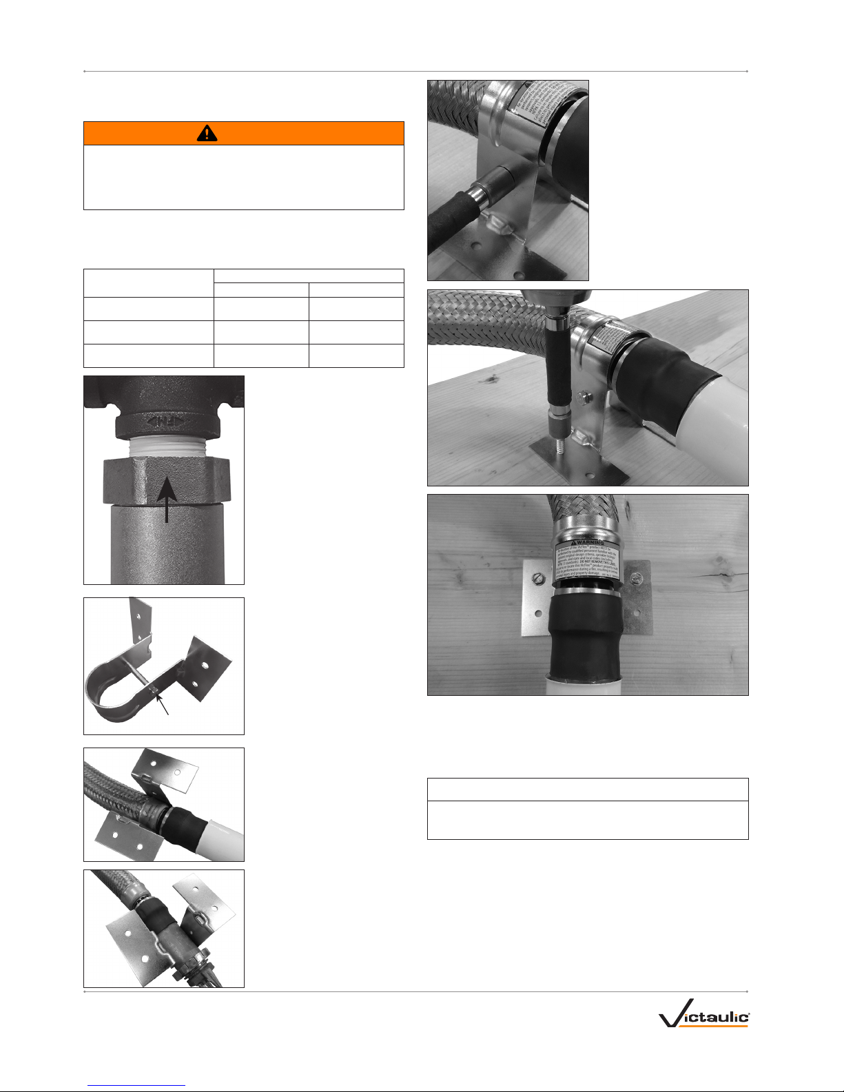
• VICTAULIC®VICFLEX™STYLE VB2 BRACKET ASSEMBLIES
SHALL BE USED ONLY WITH STYLE VS1 RECESSED PENDENT
SPRINKLERS.
• VICTAULIC®VICFLEX™STYLE VB3 BRACKET ASSEMBLIES
SHALL BE USED ONLY WITH STYLE VS1 CONCEALED
PENDENT SPRINKLERS.
• DO NOT paint, coat, plate, or alter Style VS1 Dry Sprinklers. Style
VS1 Dry Sprinklers that have been altered from their manufactured
condition may not function properly and will void any agency
listings and/or approvals.
• DO NOT test Style VS1 Dry Sprinklers with a heat source. The
glass bulb can weaken or shatter if exposed to a heat source
during testing.
• Style VS1 Dry Sprinklers that have operated cannot be
reassembled or reused, per NFPA requirements. When replacing
sprinklers, use new sprinklers of the same type, orifice,
temperature, and response.
• DO NOT clean Style VS1 Dry Sprinklers with soapy water,
detergents, ammonia, cleaning fluids, or other chemicals. Remove
any dust, lint, etc. with a soft, dry cloth.
• Inspect Style VS1 Dry Sprinklers on a regular basis for corrosion,
mechanical damage, obstructions, etc. The frequency of
inspections may vary due to corrosive atmospheres/water supplies
and activities around the sprinklers.
• DO NOT hang anything from or attach anything to Style VS1 Dry
Sprinklers. Obstructing the discharge pattern will prevent the
sprinkler from operating properly.
• The owner is responsible for maintaining the fire protection system
in proper operating condition.
• For minimum maintenance and inspection requirements, refer to
NFPA 25 and any other applicable NFPA standards that describe
the care and maintenance of sprinkler systems. In addition, the
authority having jurisdiction may have additional maintenance,
testing, and inspection requirements that shall be followed.
WARNING
• Replacement/relocation of this Victaulic®VicFlex™Style VS1
Dry Sprinkler SHALL be performed by qualified personnel
familiar with the system’s original design criteria, sprinkler
listings/approvals, and state and local codes (including NFPA 13
standards).
Failure to replace/relocate a Style VS1 Dry Sprinkler properly could
affect its performance during a fire, resulting in serious personal
injury and property damage.
* Reference UL 2443: Section 25.1
STYLE VS1 SPRINKLER ASSEMBLY DRAWING
3
2
1
Recessed Pendent Shown Above
Item Description
1Swivel Hex Nut
2Weld Fitting
3Inlet