Victaulic VicFlex AH1 User manual

victaulic.com
10.95 8507 Rev AUpdated 11/2015 © 2015 Victaulic Company. All rights reserved.
ALWAYS REFER TO ANY NOTIFICATIONS AT THE END OF THIS DOCUMENT REGARDING PRODUCT INSTALLATION, MAINTENANCE OR SUPPORT.
1.0 PRODUCT DESCRIPTION
Available Sizes by Component
• Series AH1 Braided Hose: 31, 36, 48, 60, 72"/790, 914, 1220, 1525, 1830 mm. Note: length includes adapter
nipple and 5.75"/140 mm straight reducer.
• Sprinkler Reducers: ½" and ¾"/15 and 20 mm sprinkler connections and 5.75"/140 mm, 9"/230 mm, 13"/330 mm
straight lengths and short, long 90º elbows. Note: The short 90° elbow is typically used with concealed sprinklers
while the long 90º elbow is typically used in the installation of recessed pendent sprinklers.
• Adapter Nipples: 1"/25 mm NPT or BSPT adapter nipples for attaching to pipe and fittings outlined in NFPA
standards. ¾"/20 mm NPT or BSPT available for VdS. 1 ¼"/ 32mm BSPT available for LPCB.
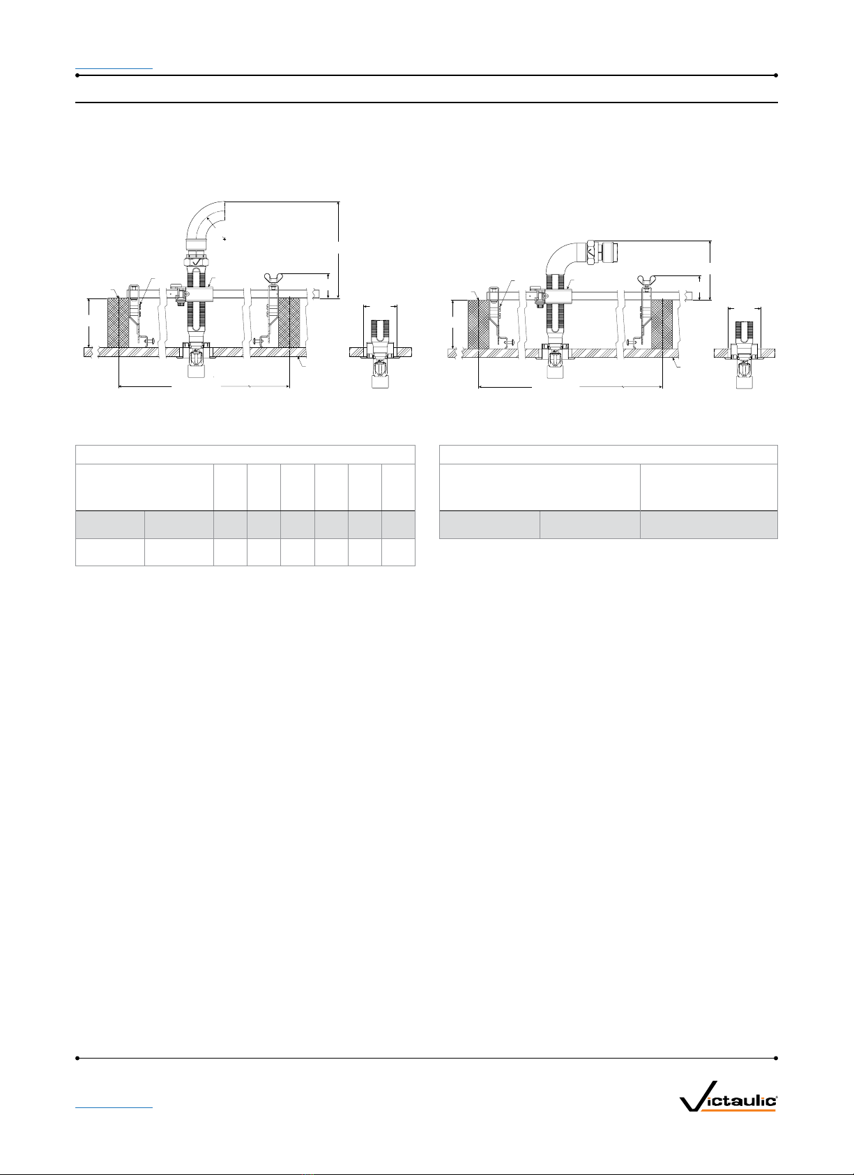
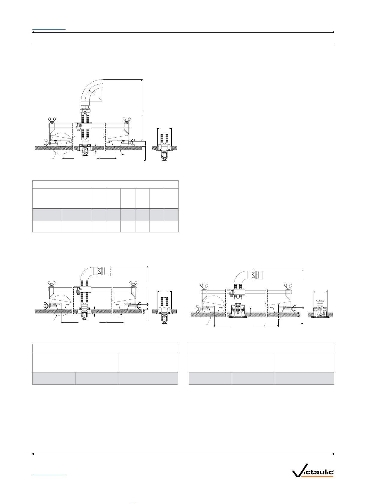
• Brackets:
• Style AB1 for suspended and hard-lid ceilings, allows installation before ceiling tiles in place
• Style AB2 for suspended and hard-lid ceilings, allows for vertical sprinkler adjustment, and installation before
ceiling tiles in place
• Style AB3 for surface mount applications, wood, metal and block walls
• Style AB4 for hard-lid ceilings with hat furring channel grid systems, allows for vertical sprinkler adjustment
• Style AB6 for cold storage applications, refer to submittal 10.90
• Style AB7 for suspended and hard-lid ceilings
• Style AB7 Adjustable for suspended and hard-lid ceilings
• Style AB8 for hard-lid ceilings with CD 60/27 profile metal studs (regionally available)
• Style AB9 for hard-lid ceilings with hat furring channel grid systems
• Style AB10 for Armstrong®TechZone™ceilings
Maximum Working Temperature
• 225°F/107°C
Maximum Working Pressure
• 200 psi/1375 kPa (FM Approval)
• 175 psi/1206 kPa (cULus Listed)
• 1600 kPa/232 psi (VdS/LPCB Approved)
Victaulic®Vic-Flex™ Sprinkler Fittings
Series AH1 Braided Flexible Hose 10.95
1
System No. Location
Submitted By Date
Spec Section Paragraph
Approved Date

10.95 8507 Rev AUpdated 11/2015 © 2015 Victaulic Company. All rights reserved.
victaulic.com 2
victaulic.com
1.0 PRODUCT DESCRIPTION (Continued)
Connections
• To adapter nipple (inlet) via 1"/25.4 mm NPT or BSPT male thread
OR
• To adapter nipple (inlet) via ¾"/20 mm BSPT male thread(VdS only)
• To sprinkler head (outlet) via ½" or ¾"/15 mm or 20 mm
Minimum Bend Radius
• 7"/178 mm (FM Approval)
• 3"/76.2 mm (cULus Listed)
• 3"/76.2 mm (VdS/LPCB Approved)
Maximum Allowable Sprinkler K-Factors
• FM (½"/15mm reducer) K5.6/8,1 (S.I.),(¾"/20mm reducer) K14.0/20,2 (S.I.)
• cULus (½"/15mm reducer) K8.0/11,5 (S.I.),(¾"/20mm reducer) K14.0/20,2 (S.I.)
• VdS/LPCB (½"/15mm reducer) K5.6/8,1 (S.I.),(¾"/20mm reducer) K8.0/11,5 (S.I.)
2.0 CERTIFICATION/LISTINGS
3.0 SPECIFICATIONS – MATERIAL
Series AH1
• Flexible Hose: 300-series Stainless Steel
• Collar/Weld Fitting: 300-series Stainless Steel
• Gasket Seal: Victaulic EPDM
• Isolation Ring: Nylon
• Nut and Nipple: Carbon Steel, Zinc Plated
• Reducer (½ or ¾"): Carbon Steel, Zinc-Plated
Brackets: Carbon Steel, Zinc-Plated

10.95 8507 Rev AUpdated 11/2015 © 2015 Victaulic Company. All rights reserved.
victaulic.com 3
victaulic.com
4.0 DIMENSIONS
Product Details - Series AH1Braided Hose
B
A
3
7
1
2
4
6
5Item Description
1 Flexible Hose
2 Isolation Ring
3 Gasket
4 Nut
5 Branch Line Nipple
6 Braid
7 Collar/Weld Fitting
Hose Length Dimensions
Hose Length A B
inches
mm
inches
mm
inches
mm
31/790 25.25/641 31/790
36/915 31.25/794 36/915
48/1220 42.25/1073 48/1220
60/1525 54.25/1378 60/1525
72/1830 66.25/1683 72/1830
Standard Reducer
5.75"/140 mm straight reducer
Optional Reducers
9.0"/229 mm straight reducer
13.0"/330 mm straight reducer
Short 90° elbow reducer Long 90° elbow reducer
NOTE
• The Short 90° elbow reducer is typically used with concealed sprinklers while the longer 90 elbow is typically used in the installation of recessed pendent
sprinklers.
2.62"/
66.5 mm
4.83"/
122.7 mm
6.57"/
166.9 mm
2.62"/
66.5 mm
1
2
3
4
–
–
–
–
–
–
–
––
–
–
–
–
–
–
–

10.95 8507 Rev AUpdated 11/2015 © 2015 Victaulic Company. All rights reserved.
victaulic.com 4
victaulic.com
4.1 DIMENSIONS
VicFlex Brackets
Style AB1
• Suspended Ceilings
• Hard-Lid Ceilings (FM Only)
Item Description
1 24"/610 mm or 48"/1220 mm Square Bar*
2 Patented Center Bracket
3 End Bracket
*Both sizes FM/VdS/LPCB approved, cULus listed
Style AB2
• Suspended Ceilings
• Hard-Lid Ceilings
Item Description
1 24"/610 mm or 48"/1220 mm Square Bar*
2 Patent-Pending adjustable Center bracket
3 End Bracket
*Both sizes FM/VdS/LPCB approved, cULus listed
Style AB3
• Surface Mount Applications
• FM Approved
3
2
1
3
3
1
27
4
5
3
6

10.95 8507 Rev AUpdated 11/2015 © 2015 Victaulic Company. All rights reserved.
victaulic.com 5
victaulic.com
4.2 DIMENSIONS
VicFlex Brackets
Style AB4
• Hard-Lid Ceilings with Hat furring
channel grid system
Item Description
1 24"/610 mm or 48"/1220 mm Square Bar*
2 Patent-Pending adjustable Center bracket
3 End Bracket for Hat Furring Channel
*Both sizes FM/VdS approved, cULus listed
Style AB7
• Suspended Ceilings
• Hard-Lid Ceilings
Item Description
1 24"/610 mm or 48"/1220 mm Square Bar*
2 Patented 1-Bee2® Center Bracket
3 End Bracket
*Both sizes FM/VdS approved.
Style AB7 Adjustable
• Suspended Ceilings
• Hard-Lid Ceilings
Item Description
1 700mm or 1400 mm Square Bar*
2 Patented 1-Bee2® Center Bracket
3 End Bracket (adjustable)
*Both sizes FM/VdS approved.
3
2
1
3
3
2
1
3
3
2
1
3
5
4

10.95 8507 Rev AUpdated 11/2015 © 2015 Victaulic Company. All rights reserved.
victaulic.com 6
victaulic.com
4.3 DIMENSIONS
VicFlex Brackets
Style AB8
• Hard-Lid Ceilings
Item Description
1 700mm or 1400 mm Square Bar*
2 Patent-pending adjustable center bracket
3 *Both sizes FM/VdS
*Both sizes FM/VdS approved.
Style AB9
• Hard-Lid ceilings with Hat furring channel
grid system
Item Description
1 24"/610 mm or 48"/1220 mm Square Bar*
2 Patented 1-Bee2® Center Bracket
3 End Bracket for Hat Furring Channel
*Both sizes FM/VdS approved.
Style AB10
• Suspended ceilings
• Armstrong®TechZone™
Item Description
1 6"/152 mm Square Bar*
2 Patented 1-Bee2® Center Bracket
3 End Bracket
*FM/VdS approved, cULus listed.
3
2
1
3
3
2
1
3
3
2
1
3

10.95 8507 Rev AUpdated 11/2015 © 2015 Victaulic Company. All rights reserved.
victaulic.com 7
victaulic.com
4.4 DIMENSIONS
CLEARANCES ABOVE CEILING
Series AH1 Braided Hose and Style AB1 Bracket
Suspended Ceiling Grid with Recessed Sprinkler Suspended Ceiling Grid with Concealed Sprinkler
V2707 MAX. EXTENSION
R
See chart
A
See Chart
V2707 ¾"/19 mm MAX. RECESS
4.4"/
113 mm
1.7"/43 mm
Typical ceiling grid
24"/610 mm
or 48"/1219 mm
on Center
/"/16 mm
Typical
ceiling tile
See note Finished
ceiling face
Bracket assembly
Style AB1
2/"/60 mm
max. hole
2"/51 mm
min. hole
R
See chart
A
See Chart
V3802 ½"/12.7 MM MAX. RECESS V3802 MAX. EXTENSION
1.7"/43 mm
Typical ceiling grid
24"/610 mm or 48"/1219 mm
on Center
/"/15.9 mm
Typical
ceiling tile
See note
Finished
ceiling face
2/"/68.3 mm
max. hole
2/"/60.3 mm
min. hole
Bracket Assembly
Style AB1
4.4"/113 mm
V2707 ¾"/19mm Max. Recess V3802 ½"/12.7mm Max. Recess
Hose Clearance Chart Hose Clearance Chart
Dimension Dimension
inches
mm
inches
mm
inches
mm
inches
mm
inches
mm
inches
mm
inches
mm
inches
mm
inches
mm
inches
mm
inches
mm
inches
mm
RMinimum
Bend Radius
2
50
3
80
4
100
5
125
6
150
7
175 RMinimum
Bend Radius
2
50
3
80
4
100
5
125
6
150
7
175
A Min. 10.75
273
11.75
298.5
12.75
324
13.75
349
14.75
375
15.75
400 A Min. 10.1
269
11.1
281
12.1
307
13.1
333
14.1
358
15.1
383
Suspended Ceiling Grid with Recessed Sprinkler with
90° Elbow (Long)
Suspended Ceiling Grid with Concealed Sprinkler with
90° Elbow (Short)
A
See Chart
4.4"/
113 mm
1.7"/43 mm
Typical ceiling grid
24"/610 mm
or 48"/1219 mm
on Center
/"/16 mm
Typical
ceiling tile
See note
Finished
ceiling face
Bracket assembly
Style AB1
V2707 MAX. EXTENSIONV2707 ¾" /19 mm MAX. RECESS
2/"/60 mm
max. hole
2"/51 mm
min. hole
See note
Finished
ceiling face
Bracket Assembly
Style AB1
24"/610 mm or
48"/1219 mm on Center
2⁄"/68 mm
max. hole
2⁄"/60 mm
min. hole
A
See Chart
⁄"/16 mm
Typical ceiling
tile
4.4"/
113 mm
1.7"/43 mm
Typical ceiling grid
V2707 ¾"/19mm Max. Recess V3802 ½"/12.7mm Max. Recess
Hose Clearance Chart Hose Clearance Chart
Dimension Dimension
inches
mm
inches
mm
A Min. 8
200 A Min. 5.8
147

10.95 8507 Rev AUpdated 11/2015 © 2015 Victaulic Company. All rights reserved.
victaulic.com 8
victaulic.com
4.5 DIMENSIONS
CLEARANCES ABOVE CEILING
Series AH1 Braided Hose and Style AB2 Bracket
Hard-lid Ceiling with Concealed Sprinkler Hard-lid Ceiling with Recessed Sprinkler
A
See chart
Finished
ceiling face
2¾"/68 mm
max. hole
2⁄ "/59 mm
min. hole
3.5"/
89 mm
16"/406 mm Stud C/C
1.8"/
45 mm
2" × 4" Stud
Bracket assembly
Style AB2
#10 Screw
R
See chart
A
See chart
Finished
ceiling face
2⁄"/60 mm
max. hole
2"/51 mm
min. hole
3.5"/
89 mm
16"/406 mm Stud C/C
1.8"/
45 mm
2" × 4" Stud
Bracket assembly
Style AB2
#10 Screw
V2707 MAX. EXTENSION
R
See chart
V2707 ¾"/19 mm MAX. RECESS
V3802 ½"/12.7mm Max. Recess V2707 ¾"/19mm Max. Recess
Hose Clearance Chart Hose Clearance Chart
Dimension Dimension
inches
mm
inches
mm
inches
mm
inches
mm
inches
mm
inches
mm
inches
mm
inches
mm
inches
mm
inches
mm
inches
mm
inches
mm
RMinimum
Bend Radius
2
50
3
80
4
100
5
125
6
150
7
175 RMinimum
Bend Radius
2
50
3
80
4
100
5
125
6
150
7
175
A Min. 7.63
193
8.63
218
9.63
244
10.63
269
11.63
295
12.63
320 A Min. 6.13
155
7.13
180
8.13
206
9.13
231
10.13
256
11.13
282
NOTE
• Variations of ceiling grids, sprinkler heads, brackets, and hoses are permitted but may result in clearance differences from the figures above.
Hard-lid Ceiling Grid with Concealed Sprinkler with
90° Elbow (Short)
Hard-lid Ceiling with Recessed Sprinkler with
90° Elbow (Long)
A
See chart
Finished
ceiling face
2¾"/68 mm
max. hole
2⁄ "/59 mm
min. hole
3.5"/
89 mm
16"/406 mm Stud C/C
1.8"/
45 mm
2" × 4" Stud
Bracket assembly
Style AB2
#10 Screw
A
See chart
Finished
ceiling face
2⁄"/60 mm
max. hole
2"/51 mm
min. hole
3.5"/
89 mm
16"/406 mm Stud C/C
1.8"/
45 mm
2" × 4" Stud
Bracket assembly
Style AB2
#10 Screw
V2707 MAX. EXTENSIONV2707 ¾"/19 mm MAX. RECESS
V3802 ½"/12.7mm Max. Recess V2707 ¾"/19mm Max. Recess
Hose Clearance Chart Hose Clearance Chart
Dimension Dimension
inches
mm
inches
mm
A Min. 5
127 A Min. 3.63
91

10.95 8507 Rev AUpdated 11/2015 © 2015 Victaulic Company. All rights reserved.
victaulic.com 9
victaulic.com
4.6 DIMENSIONS
CLEARANCES WITHIN SIDEWALL
Series AH1 Braided Hose and Style AB2 Bracket
Horizontal Sidewall Sprinkler Horizontal Sidewall Sprinkler with 90° Elbow (Long)
A
See chart
Finished
sidewall face
2⁄ "/60 mm
max. hole
2"/51 mm
min. hole
3.5"/
89 mm
16"/406 mm Stud C/C
1.8"/
45 mm
2" × 4" Stud
Bracket assembly
Style AB2
#10 Screw
R
See chart
A
See chart
Finished
sidewall face
2⁄ "/60 mm
max. hole
2"/51 mm
min. hole
3.5"/
89 mm
16"/406 mm Stud C/C
1.8"/
45 mm
2" × 4" Stud
Bracket assembly
Style AB2
#10 Screw
V2707 ¾"/19mm Max. Recess V2707 ¾"/19mm Max. Recess
Hose Clearance Chart Hose Clearance Chart
Dimension Dimension
inches
mm
inches
mm
inches
mm
inches
mm
inches
mm
inches
mm
inches
mm
RMinimum
Bend Radius
2
50
3
80
4
100
5
125
6
150
7
175 A Min. 3.63
91
A Min. 6.13
155
7.13
180
8.13
206
9.13
231
10.13
256
11.13
282

10.95 8507 Rev AUpdated 11/2015 © 2015 Victaulic Company. All rights reserved.
victaulic.com 10
victaulic.com
4.7 DIMENSIONS
CLEARANCES ABOVE CEILING
Series AH1 Braided Hose and Style AB4 Bracket
Hat Furring Channel Grid with Recessed Sprinkler
R
See chart
A
See Chart
V2707 ¾"/19.1 MM MAX. RECESS V2707 MAX. EXTENSION
/"/23 mm
Typical ceiling grid
Typical 16"/406 mm –
24"/610 mm on Center
/"/15.9 mm
Typical
ceiling tile
See note
Finished
ceiling face
2/"/60 mm
max. hole
2"/51 mm
min. hole
V2707 ¾"/19mm Max. Recess
Hose Clearance Chart
Dimension
inches
mm
inches
mm
inches
mm
inches
mm
inches
mm
inches
mm
RMinimum
Bend Radius
2
50
3
80
4
100
5
125
6
150
7
175
A Min. 10.3
262
11.3
287
12.3
313
13.3
338
14.3
363.5
15.3
389
Hat Furring Channel Grid with Recessed Sprinkler with
90° Elbow (Long)
Hat Furring Channel Grid with Concealed Sprinkler with
90° Elbow (Short)
A
See Chart
/"/23 mm
Typical ceiling grid
Typical 16"/406 mm –
24"/610 mm on Center
/"/16 mm
Typical
ceiling tile
See note
Finished
ceiling face
V2707 ¾"/19.1 MM MAX. RECESS V2707 MAX. EXTENSION
2/"/60 mm
max. hole
2"/51 mm
min. hole
See Note
Finished
ceiling face
16"/406 mm –
24"/610 mm on Center
A
See Chart
/"/23 mm
Typical ceiling grid
2/"/60 mm
max. hole
2"/51 mm
min. hole
/"/16 mm
Typical ceiling
tile
V2707 ¾"/19mm Max. Recess V2707 ¾"/19mm Max. Recess
Hose Clearance Chart Hose Clearance Chart
Dimension Dimension
inches
mm
inches
mm
A Min. 8
200 A Min. 5.9
149
NOTE
• Variations of ceiling grids, sprinkler heads, brackets, and hoses are permitted but may result in clearance differences from the figures above.

10.95 8507 Rev AUpdated 11/2015 © 2015 Victaulic Company. All rights reserved.
victaulic.com 11
victaulic.com
4.8 DIMENSIONS
CLEARANCES ABOVE CEILING
Series AH1 Braided Hose and Style AB3 Bracket
Surface Mount Application with Recessed Sprinkler
R
C
B
3¾"/
95.3 mm
A
See Note 1
2⁄"/60 mm
max. hole
2"/51 mm
min. hole
Hose Clearances
Wall Thickness
"A" 2
50
4
100
6
150
8
200
10
250
2
50
4
100
6
150
8
200
10
250
Outlet Length
"B"
5.75
146.1
9
228.6
13
330.2
5.75
146.1
9
228.6
13
330.2
9
228.6
13
330.2
13
330.2
13
330.2
5.75
146.1
9
228.6
13
330.2
5.75
146.1
9
228.6
13
330.2
9
228.6
13
330.2
13
330.2
13
330.2
Hose
Clearance "C"
11.6
294
14.8
376
18.8
478
9.6
243
12.8
325
16.8
427
10.8
275
14.8
376
12.8
325
10.8
275
12.6
319
15.8
402
19.8
503
10.6
268
13.8
351
17.8
452
11.8
300
15.8
402
13.8
351
11.8
300
Bend Radius
"R"
7
175
8
200
NOTE
• Variations of ceiling grids, sprinkler heads, brackets, and hoses are permitted but may result in clearance differences from the figures above.
• See installation instructions for mounting screw type and size.

10.95 8507 Rev AUpdated 11/2015 © 2015 Victaulic Company. All rights reserved.
victaulic.com
5.0 PERFORMANCE – FRICTION LOSS DATA
Series AH1Braided Hose with Stra ight 5.75" Reducers
Style AB1, AB2, AB4, and AB10 Brackets
Length of
Stainless Steel
Flexible Hose Outlet Size
Series AH2 Hose
Equivalent Length
of 1"/33.7 mm
Sch. 40 Pipe (C=120)
Maximum
Number of
90° Bends at 3"/51 mm
Bend Radius
inches/mm inches/mm/type feet/meters
31/775 ½"/15/Straight 52/15.8 3
¾"/20/Straight 55/16.8 3
36/900 ½"/15/Straight 63/19.2 4
¾"/20/Straight 66/20.1 4
48/1200 ½"/15/Straight 78/23.8 4
¾"/20/Straight 80/24.4 4
60/1500 ½"/15/Straight 88/26.8 4
¾"/20/Straight 90/27.4 4
72/1800 ½"/15/Straight 112/34.1 5
¾"/20/Straight 118/36.0 5
Series AH1Braided Hose Equivalent Length Design Guide
Equivalent length values at various numbers of 90 degree bends at 3"/51 mm center line bend radius
Length of
Stainless
Steel Flexible
Hose
Outlet
Size
1
Bend
2
Bends
3
Bends
4
Bends
5
Bends
inches/mm inches/mm feet/meters feet/meters feet/meters feet/meters feet/meters
31/775 ½"/15 32/9.8 42/12.8 52/15.9 N.A N.A
¾"/20 33/10.1 44/13.4 55/16.8 N.A N.A
36/900 ½"/15 33/10.1 43/13.1 53/16.2 63/19.2 N.A
¾"/20 36/11.0 46/14.0 56/17.1 66/20.1 N.A
48/1200 ½"/15 46/14.0 57/17.4 68/20.7 78/23.8 N.A
¾"/20 51/15.5 60/18.3 71/21.6 88/26.8 N.A
60/1500 ½"/15 56/17.1 67/20.4 77/23.5 88/26.8 N.A
¾"/20 58/17.7 69/21.0 80/24.4 90/27.4 N.A
72/1800 ½"/15 69/21.0 79/24.1 91/27.7 102/31.1 112/34.1
¾"/20 73/22.6 84/25.6 95/29.0 106/32.3 118/36.0
NOTES:
• Values for use with 5.75" straight reducers.
How to use this Design Guide:
• For some systems, it may be advantageous for the designer to calculate the system hydraulics using shorter equivalent lengths associated with fewer than the
maximum allowable number of bends. In this case, the designer may select a design number of bends for the job and use the associated equivalent length
from the design guide to determine the system hydraulics.
• It is possible that the actual installed condition of some of the flexible drops may have more bends than the designer selected. When this happens, the design
guide may be used to find equivalent lengths based on the actual installed number of bends for particular sprinkler installations. The system hydraulics can be
recalculated using actual equivalent lengths to verify the performance of the system.
12
victaulic.com

10.95 8507 Rev AUpdated 11/2015 © 2015 Victaulic Company. All rights reserved.
victaulic.com
5.0 PERFORMANCE – FRICTION LOSS DATA
Series AH1 Braided Hose
Style AB1, AB2, AB3, AB4, AB7, AB7 Adj., AB8, AB9 and AB10 VicFlex Brackets
Series AH1Hose
Equivalent
Length of
1"/33.7mm
Sch. 40 Pipe
Maximum
Number
of 90° Bends
at 7"/178mm
Bend Radius
inches/mm Imperial/S.I. inches/mm/type feet/meters
31/775 5.6/8.1 ½"/15/Straight 53.8/16.4 2
½"/15/90˚ Elbow 53.8/16.4
36/900 5.6/8.1 ½"/15/Straight 63.7/19.4 2
½"/15/90˚ Elbow 63.1/19.2
48/1200 5.6/8.1 ½"/15/Straight 87.9/26.8 3
½"/15/90˚ Elbow 85.8/26.1
60/1500 5.6/8.1 ½"/15/Straight 112.2/34.1 4
½"/15/90˚ Elbow 108.4/33.0
72/1800 5.6/8.1 ½"/15/Straight 136.5/41.6 4
½"/15/90˚ Elbow 131.1/39.9
31/775 8.0/11.5 ¾"/20/Straight 44.4/13.5 2
¾"/20/90˚ Elbow 47.6/14.5
36/900 8.0/11.5 ¾"/20/Straight 55.6/16.9 2
¾"/20/90˚ Elbow 57.5/17.5
48/1200 8.0/11.5 ¾"/20/Straight 82.8/25.2 3
¾"/20/90˚ Elbow 81.7/24.9
60/1500 8.0/11.5 ¾"/20/Straight 110.1/24.9 4
¾"/20/90˚ Elbow 105.9/32.2
72/1800 8.0/11.5 ¾"/20/Straight 137.3/41.8 4
¾"/20/90˚ Elbow 130.2/39.7
31/775 11.2/16.1 ¾"/20/Straight 45.5/13.8 2
¾"/20/90˚ Elbow 47.1/14.3
36/900 11.2/16.1 ¾"/20/Straight 66.3/20.2 2
¾"/20/90˚ Elbow 57.5/17.5
48/1200 11.2/16.1 ¾"/20/Straight 82.7/25.2 3
¾"/20/90˚ Elbow 82.8/25.2
60/1500 11.2/16.1 ¾"/20/Straight 109.1/33.2 4
¾"/20/90˚ Elbow 108.1/32.9
72/1800 11.2/16.1 ¾"/20/Straight 135.5/41.3 4
¾"/20/90˚ Elbow 133.4/40.6
31/775 14.0/20.2 ¾"/20/Straight 44.3/13.5 2
¾"/20/90˚ Elbow 46.4/14.1
36/900 14.0/20.2 ¾"/20/Straight 55.5/16.9 2
¾"/20/90˚ Elbow 56.7/17.3
48/1200 14.0/20.2 ¾"/20/Straight 83.0/25.3 3
¾"/20/90˚ Elbow 82.1/25.0
60/1500 14.0/20.2 ¾"/20/Straight 110.4/33.6 4
¾"/20/90˚ Elbow 107.5/32.7
72/1800 14.0/20.2 ¾"/20/Straight 137.9/42.0 4
¾"/20/90˚ Elbow 132.8/40.4
FM NOTES:
• Series AH1 has been tested and Approved by FM Global for use in wet, dry and preaction systems per NFPA 13, 13R, and 13D and FM data sheets 2-0, 2-5,
and 2-8. FM 1637 and Vds standards for safety include, but are not limited to, pressure cycling, corrosion resistance, flow characterisitics, vibration resistance,
leakage, mechanical and hydrostatic strength.
• Differences in equivalent lengths are due to varying test methods, per FM 1637 and VdS standards. Refer to these standards for additional information
regarding friction loss test methods.
• EXAMPLE: A 48-inch hose installed with two 30° bends and two 90° bends at a 7-inch bend radius is permitted and considered equivalent to the data in the
table shown above. In this example, the total number of degrees is 240°, which is less than the allowable 270°.
13
victaulic.com

10.95 8507 Rev AUpdated 11/2015 © 2015 Victaulic Company. All rights reserved.
victaulic.com
5.0 PERFORMANCE – FRICTION LOSS DATA
Series AH1 Braided Hose
Style AB1, AB2, AB4, AB7, AB7 Adj., AB8, AB9, and AB10 Brackets
Length of
Stainless Steel
Flexible Hose
Series AH1 Hose
Outlet
Size
Equivalent Length of
steel pipe according to
EN 10255 DN 25
(33,7 x 3,25)
Maximum Number
of 90º Bends at
3"/76.2mm Bend
Radius
mm/inches mm/inches/type meters/feet meters/feet
790/31 15mm/½"/Straight 4.0/12.9 3
20 mm/¾"/Straight
915/36 15mm/½"/Straight 4.6/15.0 3
20 mm/¾"/Straight
1220/48 15mm/½"/Straight 6.1/20.0 3
20 mm/¾"/Straight
1525/60 15mm/½"/Straight 7.6/25.0 4
20 mm/¾"/Straight
1830/72 15mm/½"/Straight 9.2/30.0 4
20 mm/¾"/Straight
VDS CEILING MANUFACTURERS LIST
AB1, AB2, AB7, AB10 AB4/9 AB8
1. AMF
2. Armstrong
3. Chicago Metallic
4. Dipling
5. Durlum
6. Geipel
7. Gema-Armstrong
8. Hilti
9. Knauf
10. Lafarge
11. Linder
12. Odenwald
13. Richter
14. Rigips
15. Rockfon Pagos
16. Suckow & Fischer
17. USG Donn
No specific approval 1. Hilti
2. Knauf
3. Lafarge
4. Lindner
5. Rigips
Series AH1 Braided Hose
Style AB1 Bracket
Length of
Stainless
Steel
Flexible
Hose
Series AH1 Hose
Length of
Stainless
Steel
Flexible
Hose
Series AH1 Hose
Outlet
Size
Equivalent Length
of steel pipe
according to
EN 10255 DN
(33,7 x 3,25)
Maximum
Number of
90º Bends at
3"/76.2mm
Bend Radius
Outlet
Size
Equivalent Length
of steel pipe
according to
EN 10255 DN 25
(33,7 x 3,25)
Maximum
Number of
90º Bends at
3"/76.2mm
Bend Radius
mm/inches mm/inches/type meters/feet mm/inches mm/inches/type meters/feet
790/31 15mm/½"/Straight 12.7/41.8 2 790/31 15mm/½"/90ºElbow 13.6/44.6 2
20 mm/¾"/Straight 20 mm/¾"/90ºElbow
915/36 15mm/½"/Straight 16.4/53.8 3 915/36 15mm/½"/90ºElbow 16.9/55.4 3
20 mm/¾"/Straight 20 mm/¾"/90ºElbow
1220/48 15mm/½"/Straight 19.6/64.3 3 1220/48 15mm/½"/90ºElbow 19.9/65.1 3
20 mm/¾"/Straight 20 mm/¾"/90ºElbow
1525/60 15mm/½"/Straight 24.0/78.8 3 1525/60 15mm/½"/90ºElbow 24.5/80.2 3
20 mm/¾"/Straight 20 mm/¾"/90ºElbow
1830/72 15mm/½"/Straight 28.5/93.4 3 1830/72 15mm/½"/90ºElbow 27.8/91.1 3
20 mm/¾"/Straight 20 mm/¾"/90ºElbow
14
victaulic.com

10.95 8507 Rev AUpdated 11/2015 © 2015 Victaulic Company. All rights reserved.
victaulic.com
User Responsibility for Product Selection and Suitability
Each user bears final responsibility for making a determination as to the suitability of
Victaulic products for a particular end-use application, in accordance with industry
standards and project specifications, as well as Victaulic performance, maintenance,
safety, and warning instructions. Nothing in this or any other document, nor any verbal
recommendation, advice, or opinion from any Victaulic employee, shall be deemed to
alter, vary, supersede, or waive any provision of Victaulic Company's standard conditions
of sale, installation guide, or this disclaimer.
Intellectual Property Rights
No statement contained herein concerning a possible or suggested use of any material,
product, service, or design is intended, or should be constructed, to grant any license
under any patent or other intellectual property right of Victaulic or any of its subsidaries
or affiliates covering such use or design, or as a recommendation for the use of such
material, product, service, or design in the infringement of any patent or other intellectual
property right. The terms “Patented” or “Patent Pending” refer to design or utility patents
or patent applications for articles and/or methods of use in the United States and/or other
countries.
Note
This product shall be manufactured by Victaulic or to Victaulic specifications. All products
to be installed in accordance with current Victaulic installation/assembly instructions.
Victaulic reserves the right to change product specifications, designs and standard
equipment without notice and without incurring obligations.
Installation
Reference should always be made to I-VICFLEX-AB1-AB2-AB10, I-VICFLEX-AB4-AB9,
I-VICFLEX-AB7, or I-VICFLEX-AB8 for the product you are installing. Handbooks are
included with each shipment of Victaulic products for complete installation and assembly
data, and are available in PDF format on our website at www.victaulic.com.
Warranty
Refer to the Warranty section of the current Price List or contact Victaulic for details.
Trademarks
Victaulic
and all other Victaulic marks are the trademarks or registered trademarks of
Victaulic Company, and/or its affiliated entities, in the U.S. and/or other countries.
6.0 NOTIFICATIONS
WARNING
• It is the responsibility of the system designer to verify suitability of 300-series stainless steel flexible hose for use
with the intended fluid media within the piping system and external environments.
• The effect of chemical composition, pH level, operating temperature, chloride level, oxygen level, and flow rate on
300-series stainless steel flexible hose must be evaluated by the material specifier to confirm system life will be
acceptable for the intended service.
Failure to follow these instructions could cause product failure, resulting in serious personal injury and/or property
damage.
7.0 REFERENCE MATERIALS – CHARACTERISTICS
Flexible Hose In-Plane Bend Characteristics
One Bend Two Bends Three Bends
Minimum
bend radius
90°
Minimum
bend radius
Minimum
bend radius
2X
Minimum
bend radius
OR
Minimum
bend radius
Minimum
bend radius
Minimum
bend radius
2X
Minimum
bend radius
Minimum
bend radius
OR
NOTE
• For out-of-plane (three-dimensional) bends, care must be taken to avoid imparting torque on the hose.
15
victaulic.com

175 PSI WWP Bronze Angle Valves
MATERIAL LIST
PART SPECIFICATION
1. Handwheel Nut 300 Series Stainless Steel
2. Identification Plate Aluminum
3. Handwheel Aluminum Commercial Alloy C38000
4. Stem Silicon Bronze ASTM B371 Alloy C69430
5. Packing Gland Bronze ASTM B62/ ASTM B16†/
ASTM B584 Alloy C84400
6. Packing Nut Bronze ASTM B62/
ASTM B584 Alloy C84400/ASTM B16
7. Packing Non Asbestos Aramid Fibers w/Graphite
8. Bonnet Bronze ASTM B62 Alloy C83600
9. Disc Holder Nut Bronze ASTM B62 Alloy C83600
10. Disc Holder Bronze ASTM B62 Alloy C83600
11. Seat Disc Nitrile (W) (11/4" - 2")
PTFE (Y) (21/2" - 3")
12. Seat Disc Nut Bronze ASTM B62‡/ ASTM B96
Alloy C65100 w/SS Washer
13. Body Bronze ASTM B62/B584 Alloy C83600
‡ 2¹⁄₂" and 3" size only.
† Not on 2"
175 PSI/12.1 Bar Non-Shock Cold Water
DIMENSIONS—WEIGHTS—QUANTITIES
Dimensions
Size A B H Weight Box Master
In. mm. In. mm. In. mm. In. mm. Lbs. Kg. Qty. Ctn. Qty.
1¹⁄₄ 32 2.19 56 6.13 156 2.19 56 3.71 1.69 1 10
1¹⁄₂ 40 2.38 60 7.19 183 2.38 60 5.54 2.52 1 10
2 50 2.25 57 7.25 184 2.25 57 6.72 3.05 1 10
**2¹⁄₂ 65 3.19 81 10.56 268 3.19 81 16.13 7.33 1 2
**3 80 3.88 86 11.13 283 3.88 86 21.72 9.87 1 2
* UL/ULC Listed for sizes for trim and drain use (Subject 258) - Sizes 1¹⁄₄", 1¹⁄₂", 2".
** Sizes 2¹⁄₂" and 3" supplied as T-311-Y with PTFE seat disc. Subject to AHJ Approval.
NOTE: See KT-67-UL for 1/2"-1" sizes.
T-301-W
Threaded
T-301-W
NPT x NPT
Dezincification
Resistant
NIBCO INC. WORLD HEADQUARTERS • 1516 MIDDLEBURY ST. • ELKHART, IN 46516-4740 • USA • PH: 1.800.234.0227
TECH SERVICES PH: 1.888.446.4226 • FAX: 1.888.336.4226 • INTERNATIONAL OFFICE PH: +1.574.295.3327 • FAX: +1.574.295.3455
www.nibco.com
12
AHEAD OF THE FLOW®
www.nibco.com
Revision 11/14/2014

Backflow Direct Tamper Switch Recommendation
At Backflow Direct we are committed to making our products as easy to install as possible. We design for
most contingencies, but installation may be different based on your regional regulations or system design.
We are continually improving our products and instructions –please help us by providing recommendations
as to how we can improve or products or instructions.
If you have any difficulties at all, please give us a call. Thank you for purchasing our product!
IMPORTANT NOTE: We use Stainless Steel Hardware where possible. Therefore, it is best to have Silver Anti-
seize available to use on all non-wetted bolts—only a small amount is needed.
WARRANTY INFORMATION: Please visit our website for our official warranty www.backflowdirectwarranty.com
READ INSTRUCTIONS IN FULL BEFORE INSTALLATION.
QUESTIONS? CALL 916-760-4524 M-F 8:00 AM –4:30 PM PST
REV: A | 01/10/2017 | BD-INST-TS

Backflow Direct Tamper Switch Recommendation
QUESTIONS: Please call us at 916-760-4524 M-F 8:00 AM –4:30 PM PST or email us at techhelp@backflowdirect.com
BD-INST-TS | Rev A | 01/10/2017 | Copyright 2011 Backflow Direct, LLC Page 2 of 4
Important Note: Backflow Direct recommends using a weather proof rigid ½” 90 degree pull elbow, a weather proof rigid ½” LB Conduit
Body and ½” close nipples (x2) for installation of tamper switches to fire alarm panel.
#2 Philips Head Screwdriver
Tools Required: This list is the recommended tools for ease of installation. Other versions of the same tool can be used. For
example,Allen Wrenches instead ofAllen Drive Sockets.
½” 90 degree pull elbow
½” LB Conduit Body ½” close nipples (x2)

Backflow Direct Tamper Switch Recommendation
Note: The weatherproof cover may need to be removed to run leads through the elbow. The cover can be removed by using a Philips
head screw driver to remove the screws located on the cover.
BD-INST-TS | Rev A | 01/10/2017 | Copyright 2011 Backflow Direct, LLC
Install 90 Degree Pull Elbow
A. If the pull elbow did not come with a threaded end attach a ½” close nipple to the 90 degree pull elbow.
B. run the electrical leads from the gearbox through the 90 degree pull elbow and then attach the 90 degree pull elbow by inserting
the close nipple into the threaded port on the gearbox.
C. If the cover plate was removed reinstall the cover plate and turn the 90 degree pull elbow to a 45 degree angle upwards to allow
room for LB Conduit body installation.
Page 3 of 4
AB
C

Backflow Direct Tamper Switch Recommendation
BD-INST-TS | Rev A | 01/10/2017 | Copyright 2011 Backflow Direct, LLC
Install LB Conduit Body
D. Attach the second ½” close nipple to LB Conduit body to the threaded port that is
located at the 90 degree angle.
E. Attach the LB Conduit body to 90 degree pull elbow and run electrical leads
through the close nipple into the LB Conduit body.
F. Attach to fire alarm panel leads and reinstall the weatherproof cover on the LB
Conduit body.
G. Attach flex conduit to remaining threaded port on LB Conduit body to create a
weatherproof seal.
Page 4 of 4
D
EFG
Note: The weatherproof cover may need to be removed to run leads through the conduit body. The cover can be removed by using a
Philips head screw driver to remove the screws located on the cover.
Other manuals for VicFlex AH1
1
Table of contents
Other Victaulic Irrigation System manuals

Victaulic
Victaulic FireLock Series User manual

Victaulic
Victaulic V9 FireLock IGS User manual

Victaulic
Victaulic FireLock I-800 User manual

Victaulic
Victaulic VicFlex V32 User manual

Victaulic
Victaulic VicFlex I-VICFLEX.AQC-U User manual

Victaulic
Victaulic VicFlex Style AB6 User manual

Victaulic
Victaulic VicFlex VS1 User manual

Victaulic
Victaulic FireLock Series User manual

Victaulic
Victaulic FireLock I-800 User manual

Victaulic
Victaulic VS1 Series User manual