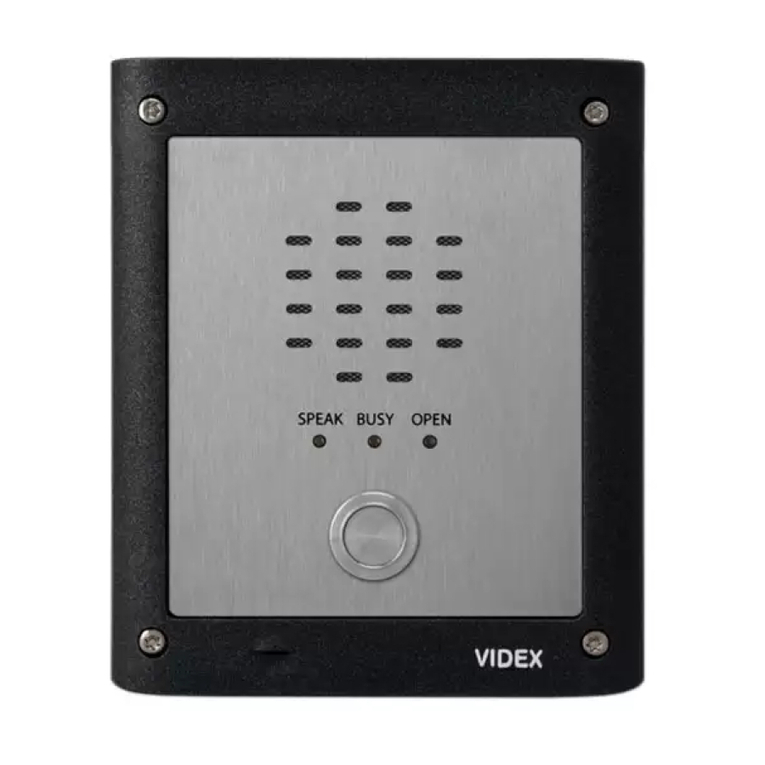
Videx 4212 Series User manual

INDUCTION LOOP GUIDE EN-UK
V.1.1
19/10/16
INDUCTION LOOP GUIDE
WE RECOMMEND
This equipment be installed by a
Competent Electrician, Security
Installation or Communications Engineer.

2
INDUCTION LOOP GUIDE
Induction Loop Guide EN-UK - V.1.1 - 19/10/16
CONTENTS
INTRODUCTION 3
• Audio 4K Series Speaker Modules 3
• Audio & Video 4K Series Speaker & Camera Modules 3
• Audio VR4K & VR Series Speaker Modules 3
USER OPERATION 3
ART.4846/IND MODULE 3
VR4KIND MODULE 3
INDUCTION LOOP PACK 4
MOUNTING TO 4K SERIES FRONT SUPPORT FRAME 4 - 5
• 4846/IND 4
• VR4KIND 5
TECHNICAL SPECIFICATION 5
CONNECTING TO A 4K SERIES SPEAKER MODULE 6 - 8
CONNECTING TO A VR4K SERIES SPEAKER MODULE 9 - 11
WIRING DIAGRAM 12
INDUCTION LOOP OPERATION 13
TROUBLESHOOTING 13
TESTING THE INDUCTION LOOP 14
• USING AN INDUCTION LOOP RECEIVER 14 - 15

3
INDUCTION LOOP GUIDE
Induction Loop Guide EN-UK - V.1.1 - 19/10/16
INTRODUCTION
This guide is intended to give an introduction to the 4K series and VR4K series Induction Loop
module and show how to connect the Induction Loop to any of the following 4K series, VR4K series
and other VR digital speaker modules:
To meet DDA requirements and the Equality Act.2010 the Induction Loop module can connect to
Videx 4000 series audio amplifier modules (both the standard 4K series and VR4K series as listed above)
to enable users with a hearing aid set to the ‘T’ position to hear the conversation from the intercom
panel.
Audio 4K Series Speaker Modules
Art.4836, Art.4837, Art.4838, Art.4203, Art.4810N/4810 (GSM speaker), 4K digital (4202 series) including
the Art.4212 digital series.
Audio & Video 4K Series Speaker & Camera Modules
Art.4833, Art.4832 and Art.4283.
Audio VR4K & VR Series Speaker Modules
VR4KAM (136 speaker), VR4KAM2W (138N speaker), VR4KAMK (140 speaker), VR4KGSM (150 GSM
speaker) and VR digital 2202-1-pcb’s.
USER OPERATION
The end user must set their hearing aid to the ‘T’ position.
ART.4846/IND MODULE
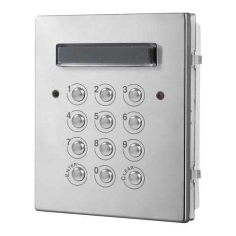
The Art.4846/IND module comprises of an IL-EL42-2 Induction Coil fitted to a transparent
polycarbonate cover window with side clips for fixing into the 4K series range of front support
frames. It has a mirror finish stainless steel front plate (standard 4K version) with a central window
(size 83x103mm).
The Art.4846/IND module box contains the following:
• A copy of this Induction Loop Guide.
• 4K panel care leaflet.
• Induction Loop Pack.
• Adhesive gasket.
VR4KIND MODULE
The VR4KIND module comprises of an IL-EL42-2 Induction Coil which is mounted to a transparent
polycarbonate cover window. It is fitted to a brushed 2.5mm (12SWG) stainless steel VR4K series
front plate with a central window (size 52x85mm) and comes with two frame mounting brackets to
fit into the 4K series range of front support frames.
The Art.VR4KIND module box contains the following:
• A copy of this Induction Loop Guide.
• VR panel care leaflet.
• Induction Loop Pack.
• 2x frame mounting brackets, 4xM3 fixing screws.

4
INDUCTION LOOP GUIDE
Induction Loop Guide EN-UK - V.1.1 - 19/10/16
INDUCTION LOOP PACK
The Induction Loop pack should contain the following parts:
• 12Vdc power cable.
• Red/Blue 4mm male bullet connector Induction Loop cable.
• Red/Blue 4mm female bullet connector Speaker cable.
• 2x Scotchlok™ 3 way butt connector.
MOUNTING TO 4K SERIES FRONT SUPPORT FRAME
1. Remove thin lm from adhesive gasket and t as shown in Fig.A.
2. Clip Art.4846/IND induction loop module into front support frame as shown in Fig.A.
1.
2.
Art.4846/IND
Fig.A

5
INDUCTION LOOP GUIDE
Induction Loop Guide EN-UK - V.1.1 - 19/10/16
TECHNICAL SPECIFICATION
It is important that the Induction Loop module (both the 4846/IND and VR4KIND) is powered by a
separate12Vdc (3A) power supply.
Supply Voltage: 12V-14Vdc.
Quiescent Current: 50mA.
Operating Current: 2A (minimum).
LED1: Power indication LED shows the device is powered ON.
LED2: Active LED shows the device is operating correctly.
LED3: Overdrive LED indicates the audio signal of the device.
VR4KIND
1. Fit VR4KIND module as shown in Fig.B.
2. Use the M3x6 xing screws to x the frame mounting brackets as shown in Fig.B.
1.
2.
M3x6 xing screws
Fig.B

6
INDUCTION LOOP GUIDE
Induction Loop Guide EN-UK - V.1.1 - 19/10/16
CONNECTING TO A 4K SERIES SPEAKER MODULE
In the following example an Art.4836 speaker is used. The instructions below can be followed when
fitting the Induction Loop to any of the 4K series speaker (and camera) modules including the digital
Art.4202 series and Art.4212 series speakers as described on page 3.
1. First ensure that any power connections are
disconnected from the 4K series speaker
module and disconnect any other wires
from the speaker terminals.
2. If it hasn’t already been done, remove the
4K series speaker module from the front
support frame.
3. Unclip the front metal speaker fascia from
the module’s back plastic, as shown in Fig.1.
4. Take a pair of wire cutters and cut the Red
and Blue speaker wires, as shown in Fig.2.
5. Unscrew the pcb screw in the middle of the
speaker pcb in order to manoeuvre the pcb
inside the back plastic (do not remove the
pcb), refer to Fig.2.
6. Take the Red/Blue female connector cable
and feed it through the underside of the
speaker pcb, coming in from the right hand
side of the speaker terminals (the ends of
the Red and Blue wires will eventually come
out at the top end of the pcb) as shown in
Fig.3.
7. Take one of the Scotchlok™ 3 way butt
connectors with the transparent side facing
up.
8. Next take the Red wires from the speaker
and the speaker pcb and the red wire from
the Red/Blue female connector cable. Feed
each wire, in turn, into one of the connector
barrels on the Scotchlok™ 3 way butt
connector, as shown in Fig.4. (When feeding
the red wires into the Scotchlok™ 3 way butt
connector they should be pushed all the way
to the end of the connector as far as they will
go, this can be seen through the transparent
side of the connector).
Fig.1
Fig.2
Fig.3
cut both speaker wires
unclip front fascia from back plastic
red/blue wires from
the female bullet cable
fed up through the
underside of the pcb
female bullet
connectors
speaker pcb wires
pcb screw

7
INDUCTION LOOP GUIDE
Induction Loop Guide EN-UK - V.1.1 - 19/10/16
9. Once the three Red wires are in position use a pair of pliers and place them over the red cap of
the butt connector and transparent side and apply pressure to crimp the wires into place, as
shown in Fig.5. (When crimping the wires into the butt connector check that the wires are firmly
held in position and do not slip out of the barrels).
10. Repeat steps 6 - 9 with the Blue speaker wires and the Blue female bullet wire.
11. Once both butt connectors have been crimped tighten up the pcb screw to secure the speaker
pcb back onto the back plastic. Replace the wire assembly back into the back plastic as well,
as shown in Fig.6. (There is enough room between the speaker pcb and the front metal fascia to
accommodate the wires. When fitting to a 4K series camera module care should be taken when
manoeuvring the wire assembly to avoid obstructing the camera lens).
12. Finally clip the front metal fascia back onto the back plastic. The Red/Blue female connector
cable should now be trailing out of the bottom corner of the 4K speaker module, as shown in
Fig.7.
Fig.4
red speaker wires
scotchlok™ 3 way
butt connector
with transparent
side facing up
red wire from
female bullet
connector cable
wires fed into
connector barrels
Fig.5
Fig.6 Fig.7
red/blue female connector cable
trailing out the bottom of the 4K
series speaker module

8
INDUCTION LOOP GUIDE
Induction Loop Guide EN-UK - V.1.1 - 19/10/16
13. Next take the 12Vdc power cable and plug
it into the power plug-in terminal at the
bottom of the Induction Loop, as shown in
Fig.8.
14. Next take the Red/Blue male connector
cable and connect it into the terminal block
at the top of the Induction Loop (the Red
wire connects into the +pos termnial and the
Blue wire connects into the GND terminal)
and remove both HDR1 jumpers, as shown
in Fig.9.
15. Finally clip the Red male/female connectors
and the Blue male/female connectors
together as shown in Fig.10. Fig.8
Fig.9
Fig.10
blue wire into the GND terminal
red wire into the + terminal
red/blue male and female
bullet connectors plugged
in together
remove HDR1 jumpers

9
INDUCTION LOOP GUIDE
Induction Loop Guide EN-UK - V.1.1 - 19/10/16
CONNECTING TO A VR4K SERIES SPEAKER MODULE
In the following example a VR4KAM 136 speaker is used. The instructions below can be followed
when fitting the Induction Loop to any VR series speaker module/pcb including the digital 2202-1-
pcb as described on page 3.
1. First ensure that any power connections are
disconnected from the VR4K series speaker
module and disconnect any other wires
from the speaker terminals.
2. Unscrew and remove the four M3x12 fixing
screws from the VR4KAM speaker module,
as shown in Fig.11.
3. Remove the top covering, as shown in
Fig.12, and remove the pcb and front
speaker plastic from the panel plate.
4. Take a pair of wire cutters and cut the Red
and Blue speaker wires (approximately half
way), as shown in Fig.13.
5. Take one of the Scotchlok™ 3 way butt
connectors with the transparent side facing
up.
6. Next take the Red wires from the speaker
and the speaker pcb and the red wire from
the Red/Blue female connector cable.
Feed each wire, in turn, into one of the
connector barrels on the Scotchlok™ 3 way
butt connector, as shown in Fig.14. (When
feeding the red wires into the Scotchlok™ 3
way butt connector they should be pushed
all the way to the end of the connector as far
as they will go, this can be seen through the
transparent side of the connector).
7. Once the three Red wires are in position use
a pair of pliers and place them over the red
cap of the butt connector and transparent
side and apply pressure to crimp the wires
into place, as shown in Fig.15. (When
crimping the wires into the butt connector
check that the wires are firmly held in position
and do not slip out of the barrels).
Fig.11
Fig.12
unscrew the
M3x12 xing
screws
Fig.13
cut both speaker wires
remove top covering
speaker plastic

10
INDUCTION LOOP GUIDE
Induction Loop Guide EN-UK - V.1.1 - 19/10/16
Fig.15Fig.14
red speaker wires
scotchlok™ 3 way
butt connector
with transparent
side facing up
red wire from
female bullet
connector cable
wires fed into
connector barrels
8. Repeat steps 6 - 7 with the Blue speaker wires and the Blue female bullet wire.
9. Once both butt connectors have been crimped replace the wire assembly back into the front
plastic, as shown in Fig.16.
10. Fold the Red/Blue female connector cable over the top side of the speaker pcb so that when the
speaker pcb sits in position on the front speaker plastic the Red/Blue connector cable runs from
the top of the speaker pcb down along the top side of the pcb, as shown in Fig.17.
11. Replace the top covering speaker plastic and fit the four M3x12 fixing screws and tighten firmly
into place, as shown in Fig.18.
12. After the top covering speaker plastic has been fitted back into position the Red/Blue female
connector cable should be trailing out from the gap of the top covering plastic just above the
terminal connections, as shown in Fig.19.
Fig.17Fig.16
Fig.14
crimped red/blue
connector wires
tucked in between
the speaker pcb
and front plastic
red/blue connector
wires folded over
the top side of the
speaker pcb

11
INDUCTION LOOP GUIDE
Induction Loop Guide EN-UK - V.1.1 - 19/10/16
Fig.19Fig.18
13. Next take the 12Vdc power cable and plug
it into the power plug-in terminal at the
bottom of the Induction Loop, as shown in
Fig.20.
14. Next take the Red/Blue male connector
cable and connect it into the terminal block
at the top of the Induction Loop (the Red
wire connects into the +pos termnial and the
Blue wire connects into the GND terminal)
and remove both HDR1 jumpers, as shown
in Fig.21.
15. Finally clip the Red male/female connectors
and the Blue male/female connectors
together as shown in Fig.22. Fig.20
Fig.21
Fig.22
red/blue male and female
bullet connectors plugged
in together
trailing red/
blue induction
loop wires out
of the gap of the
covering plastic
and over the
speaker terminals
t the
four
M3x12
xing
screws
blue wire into the GND terminal
red wire into the + terminal
remove HDR1 jumpers

12
INDUCTION LOOP GUIDE
Induction Loop Guide EN-UK - V.1.1 - 19/10/16
WIRING DIAGRAM
All speaker
variations
Speaker
Induction Loop
Scotchlok™ 3 Way
Butt Connectors
Connections to
12Vdc PSU (3A)
10KΩ resistor
10KΩ resistor
Fig.23 below shows the wiring connections from the Induction Loop pcb to any of the speaker
modules as listed on page 3.
Fig.23

13
LED1: Power Indicator
LED2: Active Indicator
LED3: Overdrive Indicator
HDR1 Jumpers
(both jumpers
should be removed)
INDUCTION LOOP GUIDE
Induction Loop Guide EN-UK - V.1.1 - 19/10/16
Fig.24
TROUBLESHOOTING
INDUCTION LOOP OPERATION
The Induction Loop has been designed
to be left unattended once it has been
correctly installed and powered ON.
Fig.24 shows the onboard LED indicators:
LED1 - POWER: If this LED is constantly
lit (red) then this indicates there is 12Vdc
power to the Induction Loop.
LED2 - ACTIVE: If the induction loop is
being driven correctly then this LED
will illuminate (green) to indicate that a
steady signal is passing through.
LED3 - OVERDRIVE: If the audio signal
level increases through the induction
loop this LED will start to illuminate red
and get brighter in intensity. If it shows a
continuous red then the drive level is too
high and audio distortion will occur.
LED1 OFF
LED1 ON, Other LEDs OFF
LED1 ON
LED2 ickers or steady
LED3 ickers regularly
LED1 ON
LED2 steady
LED3 continuously ON
LED1 ON
LED2 ickering or steady
LED3 OFF or occasionally ickers
SYMPTOM POSSIBLE FAULT ACTION
PSU disconnected or failed Investigate power supply
No audio input Investigate audio connection
Normal operation
Correct operation, although
audio input could be low
No action required
Increase audio level if possible, try
turning up speaker POT on audio
amplier
LED1 ON
LED2 OFF
LED3 continuously ON
Excessive audio input. Danger of
distortion or overheating
Induction Loop disconnected,
open circuit or incorrect
specication
Reduce audio level, try turning
down speaker POT on audio
amplier
Investigate Induction Loop and
its connections, check connected
to audio amplier correctly
Interference (buzzing, whistling
or hissing) is heard through
Induction Loop
Unscreened or poorly earthed 3rd party
equipment is being used or in close
proximity, incorrect PSU being used
Switch o 3rd party equipment
to identify the source of
interference

14
INDUCTION LOOP GUIDE
Induction Loop Guide EN-UK - V.1.1 - 19/10/16
TESTING THE INDUCTION LOOP
After the Induction Loop has been installed it
can be tested using the Contacta audio Induction
Loop receiver (part no. IL-RX20) or an equivalent
3rd party audio induction loop receiver.
This test equipment allows the engineer to listen
to an audio frequency Induction Loop system
using a standard pair of stereo headphones. It
has a vertically mounted pick up coil to emulate
the performance of a hearing aid switched to the
‘ T ’ (telecoil) position.
USING AN INDUCTION LOOP RECEIVER
While the steps below describe how to use the
Contacta IL-RX20 receiver the same steps can be
used as a guide when using a 3rd party induction
loop receiver. If any problems arise when testing
the troubleshooting guide (on page 13) can also
be used to help determine where the fault lies.
1. Ensure the Induction Loop has been
connected up correctly to the relevant
speaker module.
2. Connect 12Vdc power to the induction loop.
3. Plug the headphones in the jack connection
at the top of the IL-RX20 receiver, as shown
in Fig.25, and place the headphones over
both ears.
4. Slowly turn the volume control clockwise
until you hear a ‘click’ and the green
indication LED comes ON, as shown in Fig.26
(the receiver’s LED will stay illuminted while
in the ON position. To maximize battery life it
is recommended that the receiver is switched
OFF when not in use).
5. The receiver must be positioned in a vertical/
upright position and held in close proximity
to the induction loop when testing, as shown
in Fig.27 (do not hold the receiver flat).
Fig.26
Fig.25
volume control switch

15
INDUCTION LOOP GUIDE
Induction Loop Guide EN-UK - V.1.1 - 19/10/16
6. Place a test call from the intercom panel to
the internal intercom phone.
7. When the handset on the intercom phone
is answered check that there is clear
speech coming through the audio receiver
headphones (if required adjust the volume
control to set the speech volume to an
acceptable level).
8. When finished switch OFF the IL-RX20
receiver.
Fig.27
ensure the receiver
is held upright

Induction Loop Guide EN-UK - V.1.1 - 19/10/16
Northern Oce
Videx Security Ltd.
Unit 4-7 Chillingham Industrial Estate
Newcastle Upon Tyne
NE6 2XX
Southern Oce
Videx Security Ltd.
1 Osprey, Trinity Park
Trinity Way’ London
E4 8TD
Other manuals for 4212 Series
1
This manual suits for next models
17
Table of contents
Other Videx Control Unit manuals

Videx
Videx 4000 Series User manual

Videx
Videx 4000 Series User manual

Videx
Videx 4842 User manual

Videx
Videx Art.2270 User manual

Videx
Videx DK8K-1 User manual

Videx
Videx Vandal Resistant 4000 Series User manual

Videx
Videx 4842D User manual

Videx
Videx 4830 User manual
Videx
Videx 4800M User manual

Videx
Videx VX8800 User manual