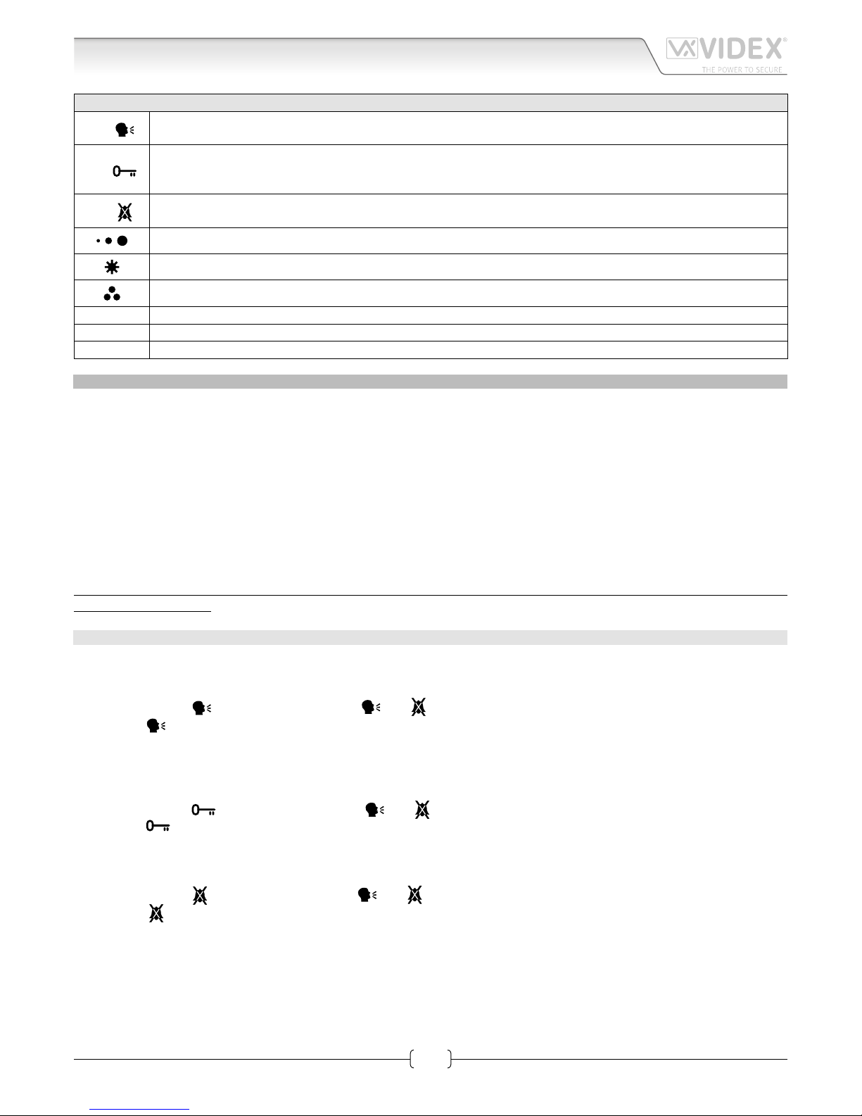
PUSH BUTTONS, LEDS AND CONTROLS FIG. 1
LED On LED.
It illuminates when the videophone is switched ON.
LED
Generic use LED.
It is supplied from the terminals “6” and “7” of the PCB connection board Art.5980. Normally used to signal the door
status (open or closed).
LED Privacy on LED.
It illuminates when the privacy service is enabled.
Call tone volume control (3 levels).
Brightness control.
Colour intensity control.
JP1 Jumper for future expansion (must remain closed).
TR1 Contrast control trimmer (rotate left to increase or right to decrease.
SWCH1 Bus termination switch (Left position = BUS termination active, Right position = BUS termination disabled)
PROGRAMMING
The videophone setup consists of the following settings:
• Number of Rings;
• Melody selection;
• Privacy duration;
• Unit address (1..127, switches 1 to 7 of SW1);
• Bus Termination (open or close, switch SWCH1);
• Intercommunication mode (between apartments or within apartment, switch 1 of SW3);
• Extension address (1..4, switches 2,3 of SW3);
• Slave mode (switch 4 of SW3).
The programming of the number of rings, melody and privacy duration are carried out through the videophone push buttons, all
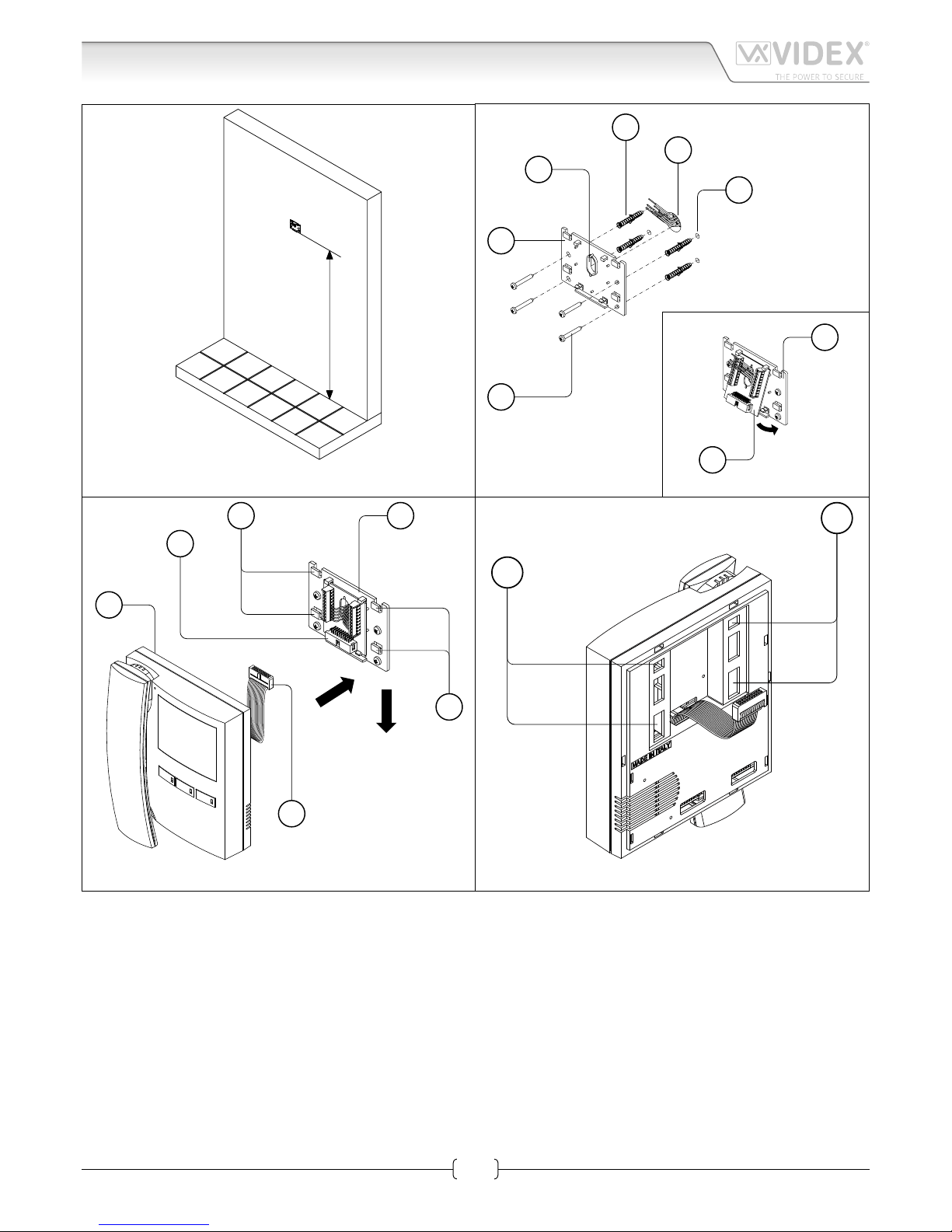
other settings are carried out on the two dip-switch banks (SW1 and SW3) on the rear side of the video monitor (all the settings can
be done without opening the videophone).
Except the number of rings programming, it is necessary to remove temporary the power supply after making any other
programming changes.
NUMBER OF RINGS, MELODY SELECTION AND PRIVACY DURATION
To make these changes, it is necessary to pick up the handset rst when the system is in stand-by.
NUMBER OF RINGS
• Keep pressed the button until the two LEDs and switch on.
• Press the button for the number of times corresponding to the required number of rings to set. A beep conrms each time
the button is pressed.
• Once the required number of rings is reached, wait approx 5 seconds for the two LED’s to switch o. The new value is stored.
MELODY SELECTION
• Keep pressed the button until the two LEDs and switch on. The unit emits the current selected melody.
• Press the button and keep it pressed to listen the next melody. Repeat the operation until the required melody is found.
• Once the required melody is found, wait approx 5 seconds for the two LED’s to switch o. The new melody is set.
PRIVACY DURATION
• Keep pressed the button until the two LEDs and are switched on.
• Press the button for the number of times corresponding to the required privacy duration to set. Each time the button is
pressed, the duration is increased by 15 minutes: i.e. to set 2 hours, press the button 8 times.
• Once the required privacy time is reached, wait approx 5 seconds for the two LED’s to switch o. The new duration is set.
Art.3686 Digital videophone