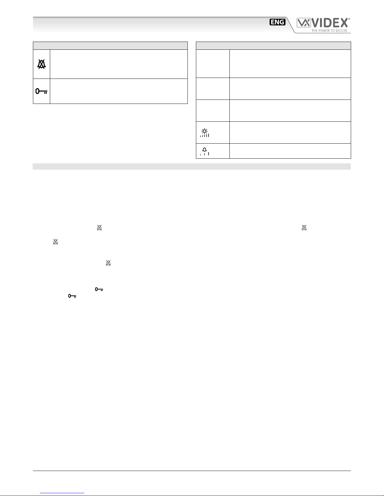
Videx 6200 Series User manual

66251125 - V2.0 - 31/05/18
- 1 -
6200 Series
Art.6276 - Installation instructions
Art.6276 3.5" colour display videophone
27 mm 144 mm
182 mm
Fig. 1 Front
+VD
+20
V1
V/V2
GNDV
L
–
LB
AL
DOL
EXTC
SW
SW
DSW1 DSW2
PT1 PT2
VR1
PT3
SW2
A
I
B
D
G
E
H
F
C
Fig. 2 Back
DESCRIPTION
Surface mount videophone for VX2200 digital systems using com-
posite video signal (coax) or balanced (twisted pair) incorporating
a 3.5”Hi-Res full colour active matrix LCD monitor, with“camera re-
call”,“door open/concierge call”,“service”and“privacy”button.
2 LED’s one for generic use (door opening usually) and one to
indicate privacy service enabled.
Programmable settings: privacy duration, video mode (coax or
balanced), melody and number of rings.
Adjustments: call tone volume (3 levels), microphone volume,
picture hue, contrast and brightness.
LEGEND
AConnection terminals
B8 Way dip switch bank to set videophone address
C4 Way dip switch bank to set video mode
DContrast adjustment trimmer
EHue adjustment trimmer
FMicrophone volume adjustment trimmer
GBrightness control sliding wheel
HCall tone volume switch
IRJ-45 connector
PUSH BUTTONS
Service button
When pressed, shorts terminal SW to SW (Max 24 Vdc 50mA).
Privacy service
Press to enable the privacy service. The LED turns on. The service is deactivated by pressing again the same button or
when the programmed time expires.
Door Open Push Button
• During a conversation, operation of this button will release the door from where the call originated. This will be conrmed
by an acoustic tone. If terminal DOL is connected, the“door open”LED under the symbol will also illuminate.
• When the system is in stand-by, picking up the handset and pressing the buttons will book a call to the concierge (If
available).
Camera recall
When the system is in standby (no calls on the system), pick up the handset then press this button to open the SPEECH/
VIDEO to the door station. Press as many time as the ID value of the door panel to connect to.

66251125 - V2.0 - 31/05/18
- 2 -
6200 Series
Art.6276 - Installation instructions
LEDS
Privacy on LED
It illuminates when the privacy service is enabled,
when pressing the service button or during program-
ming mode.
Generic use LED
It is controlled from the terminal DOL.
Normally used to signal the door status (open or closed).
CONTROLS AND ADJUSTMENTS
PT1
Contrast adjustment trimmer*
Rotate anticlockwise to increase or clockwise to
decrease.
*Not available in some LCD versions.
PT2
Hue adjustment trimmer
Rotate anticlockwise to increase or clockwise to
decrease.
VR1
Microphone volume adjustment trimmer
Rotate anticlockwise to decrease or clockwise to
increase.
PT3
Brightness control sliding wheel
Rotate anticlockwise to increase or clockwise to
decrease (when videophone is closed).
SW2 Call tone volume switch
3 levels: low, medium and high.
PROGRAMMING
The programmable settings are:
• Privacy service duration (from 15 minutes to 20 hours or innte);
• Melody (9 available);
• Number of rings (3 or 6);
• Video mode (coax or balanced);
• Videophone address (Phone ID).
TO SET PRIVACY SERVICE DURATION
1.Press and keep pressed button for 10 seconds to enter privacy service duration programming mode: the LED turns on and
the unit emits a“beep“;
2.Press button as many times as required. Each press is equal to 15 minutes: the unit emits a “beep“ every time the button is
pressed. I.E.: press 4 times for 1 hour, 12 for 3 hours. Default: innite. Max value: 20 hours. To program innite privacy time don’t
press any buttons;
3.Wait for some seconds: the LED turns o and the unit emits a “beep“ that conrms the new setting is properly stored;
4.The unit returns to stand-by mode.
TO SET MELODY
1. Press and keep pressed button for 10 seconds until the unit plays the current programmed melody and emits a“beep”at the end.
2.Press again button to listen to the available melodies (maximum 9);
3.Once the selected melody has been reached, wait 5 seconds for a“beep”;
4.The new melody will be stored.
Note: To set the melody it is required that the videophone is connected in a system where the +20Vdc voltage from Art.893N1 is
always enabled.
TO SET THE NUMBER OF RINGS 6 OR 3:
Default setting is 6, to set 3 proceed as follows:
1.Turn o the videophone by unplugging the connector from the PCB;
2.Make a short between terminals GNDV and LB on the connector;
3.Plug the connector in and wait for a beep before removing the short;
4.To go back to 6 rings, do the same but two “beeps” will be emitted.
Art.6276 3.5" colour display videophone

66251125 - V2.0 - 31/05/18
- 3 -
6200 Series
Art.6276 - Installation instructions
Art.6276 3.5" colour display videophone
TO SET THE VIDEO MODE AND TERMINATION
The videophone can operate with either composite video signal (coax cable) or balanced video signal (two wires). Switches 1 & 2 of
DSW2 are used to set video mode while switches 3 & 4 are for video termination.
VIDEO MODE DSW2
Switches 1,2 Mode
Coax
Balanced
75 OHM VIDEO TERMINATION DSW2
Switches 3,4 Termination
Enabled
Disabled
Switches 3 and 4 adjust the video signal impedance. when using more than one videomonitor in parallel (without a video
splitter) put both switches in the OFF position on all but the last videomonitor (end of line).
VIDEOMONITOR/INTERCOM ADDRESS, VIDEO MODE AND TERMINATION SETUP DSW1
Each intercom is addressed in binary (PHONE ID) using the 8 way dipswitches located on the rear of the unit. Each switch corre-
sponds to one bit which can have a value 0 (OFF) or 1 (ON). Each bit corresponds to a decimal weight depending on the position:
Switch 1 = decimal 1, 2=2, 3=4, 4=8, 5=16, 6=32, 7=64, 8=128. I.E. to set the address 37, put switches 1, 3 and 6 on (1+4+32=37).
SWITCHES DECIMAL WEIGHT ADDRESS
8 7 6 5 4 3 2 1 128 64 32 16 8 4 2 1
OFF OFF OFF OFF OFF OFF OFF ON 0 0 0 0 0 0 0 1 1
OFF OFF OFF OFF OFF OFF ON OFF 0 0 0 0 0 0 1 0 2
OFF OFF OFF OFF OFF OFF ON ON 0 0 0 0 0 0 1 1 3
OFF OFF OFF OFF OFF ON OFF OFF 0 0 0 0 0 1 0 0 4
OFF OFF ON OFF OFF ON OFF ON 0 0 1 0 0 1 0 1 37
ON OFF ON ON OFF ON OFF OFF 1 0 1 1 0 1 0 0 180
USING RJ45 PLUG TO CONNECT THE VIDEOPHONE
EIA/TIA568B
1
2
3
4
5
6
7
8
o
O
g
B
b
O
br
BR
8
7
6
5
4
3
2
1
BR
br
G
b
B
g
O
oEIA/TIA-568B
RJ-45 pin VX2200 Signal
1and 2 (white-orange / orange) L
3and 4 (white-green / blue) –
5and 6 (white-blue / green) +
7 (white-brown) V1
8 (brown) V2
EIA/TIA568A
1
2
3
4
5
6
7
8
g
G
o
B
b
O
br
BR
8
7
6
5
4
3
2
1
BR
br
O
b
B
o
G
gEIA/TIA-568A
RJ-45 pin VX2200 Signal
1and 2 (white-green / green) L
3and 4 (white-orange / blue) –
5and 6 (white-blue / orange) +
7 (white-brown) V1
8 (brown) V2
NOTE: DO NOT USE CROSS OVER CABLES.
IMPORTANT NOTE: SOLID COPPER CABLES MUST BE USED. COPPER COATED STEEL CCS AND COPPER COATED
ALUMINIUM CCA CAN NOT BE USED ON THE SYSTEM.

66251125 - V2.0 - 31/05/18
- 4 -
6200 Series
Art.6276 - Installation instructions
CONNECTION TERMINALS SIGNALS
+VD 12Vdc output to supply coax video distributor
Art.894N
+20 Video power supply 17÷20Vdc
V1 Balanced video signal V1 sync. (balanced video signal
mode)
V/V2
Balanced video signal V2 sync. (balanced video signal
mode)
Composite video signal (coax video signal mode)
GNDV Video power supply ground reference
LBUS line
– BUS line ground reference
LB Local bell input (active low)
AL Alarm input (active low)
DOL 12Vdc input to supply Aux LED
EXTC Call tone output for extension sounder (Art.512A)
SW Service button connection Max 24 Vdc
50mA
SW
TECHNICAL SPECIFICATION
Working Voltage: 17÷20Vdc
Power Consumption: During a call: 200mA
During a conversation: 120mA
Working Temperature: -10°C +50°C
MEMORY BOARD
This device is also available in the version with
memory board (Art.6276/VM).
If you have that version, please refer to the
“6200, 6300, 6400 and 6700 Series Memory
Board”user manual (in English and Italian) for
installation and use.
The manual is available for download: click/tap or scan the
QR code.
Art.6276 3.5" colour display videophone

66251125 - V2.0 - 31/05/18
- 5 -
6200 Series
Art.6276 - Installation instructions
6200 SeriesVideophone wall mounting instructions
1
2
A
A
Fig. 1 Fig. 2
135cm
Fig. 3
B
C
C
E
B
G
F
D
G
G
D
Fig. 4
A
B
H
Fig. 5
2
1
Fig. 6
Fig. 7
1. In order to install the videophone, it is necessary to remove the cover, which contains all the electronics, from the base: rstly
disconnect the handset from the videophone (by removing its plug from the videophone) then insert a 5.5mm at screw driv-
er into the clip Athen rotate clockwise until you listen a “CLICK!”.
Repeat the same operation with the other clip as shown in Fig. 1.
2. Pull outwards the top part of the cover as shown in Fig. 2. Don’t pull the cover straight.
3. Put the base of the unit on the wall at approx 135cm from the nished oor (Fig. 3) to mark the points for the xing holes B
(Fig. 4) remembering that the wires E(Fig. 4) must be fed through the hole F(Fig. 4). If you use the ush mounting box 503,
embed it into the wall vertically at approx. 140cm from the nished oor and the base.
4. Following Fig. 4, make the holes B, insert the wall plugs Cand x the base with the screws Dfeeding the wires Einto the
hole F. If you have used the box 503, x the base to the wall through the holes Gusing the screws D.
5. As shown in Fig. 5A, connect the wires to the removable terminals following the provided installation diagram. Connect the ter-
minal blocks to the electronics contained in the cover as shown in Fig. 5B. Reinsert the handset and test system before closing.
Note: Contrast and hue trimmers can be adjusted only if the videophone is open. Note while testing the system, it is
advisable to hold the cover with your hand closing manually the hook switch of the handset (see Fig. 5B reference H).
6. Once testing is complete and all the necessary adjustments are made, disconnect the handset from the cover and close the unit
as shown in Fig. 6: rst hook it on the bottom then push in the top until you hear a “CLICK!”.
7. Reconnect the handset and hang it as shown in Fig. 7.

66251125 - V2.0 - 31/05/18
- 6 -
Serie 6200
Art.6276 - Istruzioni di installazione
Art.6276Videocitofono 3,5" a colori
27 mm 144 mm
182 mm
Fig. 1 Fronte
+VD
+20
V1
V/V2
GNDV
L
–
LB
AL
DOL
EXTC
SW
SW
DSW1 DSW2
PT1 PT2
VR1
PT3
SW2
A
I
B
D
G
E
H
F
C
Fig. 2 Retro
DESCRIZIONE
Videocitofono per sistemi digitaliVX2200 con segnale video com-
posito (coassiale) o bilanciato (2 li) con monitor a colori LCD TFT
da 3,5”, pulsante “auto-accensione”, pulsante “apri-porta/chiama-
ta a portiere”, pulsante di “servizio”e pulsante Privacy.
2 LED di cui uno per segnalazioni generiche (solitamente aper-
tura porta) ed uno ad indicare l’attivazione del servizio privacy.
Programmazioni: durata privacy, modo video (coassiale o bilan-
ciato), tipo di suoneria e numero di squilli.
Regolazioni: volume suoneria (3 livelli), volume microfono, satu-
razione, luminosità e contrasto.
LEGENDA
AMorsettiera di connessione
BDip-switch ad 8 vie per l’indirizzo del videocifotono
CDip-switch a 4 vie per il settaggio del modo video
DTrimmer regolazione contrasto
ETrimmer regolazione saturazione colore
FTrimmer regolazione volume microfono
GRotella regolazione luminosità
HSwitch volume suoneria
IConnettore RJ-45
PULSANTI
Pulsante di servizio.
Se premuto vengono collegati internamente i morsetti SW e SW (Max 24 Vdc 50mA).
Servizio privacy.
Premere il pulsante per abilitare la funzione. Il LED si accende. Il servizio si disattiva automaticamente alla scadenza del
tempo programmato (la durata è programmabile) o manualmente premendo di nuovo il pulsante.
Con il servizio attivo il monitor non riceve le chiamate e quindi non emette alcun suono.
Pulsante Apri-porta.
• Premere durante la conversazione per aprire la porta dell’ingresso dal quale proviene la chiamata. L’apertura della porta
viene confermata da un segnale acustico. Se il morsetto DOL è opportunamente collegato, il relativo LED resta ac-
ceso no a quando resta aperta la porta.
• Sollevare la cornetta e premere ad impianto spento per chiamare il centralino di portineria se presente nel sistema.
Pulsante autoaccensione.
Ad impianto spento, sollevare la cornetta e premere il pulsante per eettuare l’auto-accensione ed aprire la comunicazione
verso il posto esterno. Il numero di pressioni del pulsante dipende dall’identicativo del posto esterno che si vuole accen-
dere.

66251125 - V2.0 - 31/05/18
- 7 -
Serie 6200
Art.6276 - Istruzioni di installazione
LED
LED privacy on
Si illumina quando il servizio è attivo, quando si preme
il pulsante di servizio o in modalità programmazione.
LED ad uso generico
È controllato dal morsetto DOL. Normalmente, con gli
opportuni collegamenti, viene utilizzato per segnalare
lo stato di apertura o chiusura della porta.
CONTROLLI E REGOLAZIONI
PT1
Trimmer regolazione contrasto*
Ruotare in senso antiorario per incrementare o
orario per diminuire.
*Non disponibile su alcune versioni di LCD.
PT2
Trimmer regolazione saturazione colore
Ruotare in senso antiorario per incrementare o
orario per diminuire.
VR1
Trimmer regolazione volume microfono
Ruotare in senso antiorario per diminuire o
orario per incrementare.
PT3
Rotella regolazione luminosità
Ruotare in senso antiorario per incrementare o orario
per diminuire (quando il videocitofono è chiuso).
SW2 Switch volume suoneria
3 livelli: basso, medio e alto.
PROGRAMMAZIONE
Le opzioni programmabili sono:
• Durata privacy (da 15 minuti a 20 ore, oppure innito);
• Suoneria (9 disponibili);
• Numero di squilli (3 o 6 default);
• Modo Video (coassiale o bilanciato);
• Indirizzo Videocitofono (Phone ID).
PER IMPOSTARE LA DURATA SERVIZIO PRIVACY
1.Premere e mantenere premuto il pulsante per 10 secondi per entrare in modalità programmazione durata servizio privacy: il
LED si accende e l’unità emette un “bip“;
2.Premere il pulsante tante volte quanto è il tempo richiesto. Ogni pressione corrisponde a 15 minuti. Es. premere 4 volte per
1 ora, 12 per 3 ore ecc. Default: innito. Valore massimo: 20 ore. Per impostare il valore“innito” (il servizio si disattiva solamente
premendo di nuovo il pulsante) non premere alcun pulsante;
3.Attendere alcuni secondi: il LED si spegne e l’unità emette un“bip”a conferma che la nuova impostazione è stata correttamente
registrata;
4.L’unità ritorna in modalità standby.
PER IMPOSTARE LA SUONERIA
1.Con il videocitofono in stand-by, premere e mantenere premuto il pulsante per 10 secondi no a quando l’unità riproduce la
suoneria correntemente programmata ed emette un“bip” al termine;
2.Premere nuovamente il pulsante per ascoltare le suonerie disponibili (max 9);
3.Selezionata la suoneria desiderata, attendere, senza compiere alcuna operazione, circa 5 secondi che venga emesso un “bip”;
4.La nuova suoneria è memorizzata.
Nota: Per poter impostare la suoneria, occorre che il videocitofono sia collegato ad un sistema in cui la tensione +20Vdc
dall’Art.893N1 sia sempre abilitata.
PER IMPOSTARE IL NUMERO DI SQUILLI 6 O 3:
L’impostazione di default è 6 per impostare 3 procedere come segue:
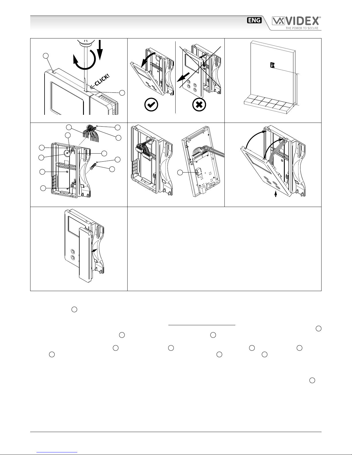
5.togliere l’alimentazione al videocitofono scollegando il cavo at dalla scheda di connessione;
6.mettere in corto i morsetti GNDV ed LB della scheda di connessione;
7.ricollegare il cavo at e attendere l’emissione di un bip prima di rimuovere il corto dai morsetti;
8.per tornare a 6 squilli, procedere alla stessa maniera ripartendo dal punto 1., ma al punto 3. verranno emessi due“bip”.
Art.6276 Videocitofono 3,5" a colori

66251125 - V2.0 - 31/05/18
- 8 -
Serie 6200
Art.6276 - Istruzioni di installazione
Art.6276 Videocitofono 3,5" a colori
PER IMPOSTARE IL MODO VIDEO E LA TERMINAZIONE
Il videocitofono può funzionare con il segnale video composito (cavo coassiale) o con il segnale video bilanciato (2 li). Gli switch
1 e 2 di DSW2 permettono di impostare il modo video mentre tramite gli switch 3 e 4 è possibile abilitare la terminazione video.
MODO VIDEO DSW2
Switch 1,2 Modo
Coassiale
Bilanciato
TERMINAZIONE VIDEO 75 OHM
Switch 3,4 Terminazione
Attiva
Disattiva
Gli switch 3 e 4 servono ad adattare l’impedenza del segnale video; in caso di più videocitofoni collegati in parallelo, devo-
no essere impostati entrambi ad OFF per tutti i videocitofoni ad eccezione dell’ultimo in ordine di collegamento.
IMPOSTAZIONE INDIRIZZO VIDEO/CITOFONO, MODO E TERMINAZIONE VIDEO DSW1
L’indirizzo del citofono/videocitofono è codicato in binario tramite il dip-switch ad 8 vie situato sul retro dell’unità. Ogni switch corrispon-
de ad un bit che può essere a 0 (OFF) o 1 (ON), a ciascun bit corrisponde un peso decimale in base alla posizione: Switch 1=decimale 1, 2=2,
3=4, 4=8, 5=16, 6=32, 7=64, 8=128 per impostare l’indirizzo desiderato, mettere ad ON (1) gli switch la cui somma dei pesi corrisponde al
valore dell’indirizzo. Ad esempio, per impostare l’indirizzo 37, mettere ad ON gli switch 1, 3 e 6 (1+4+32=37).
SWITCH PESO DECIMALE INDIRIZZO
8 7 6 5 4 3 2 1 128 64 32 16 8 4 2 1
OFF OFF OFF OFF OFF OFF OFF ON 0 0 0 0 0 0 0 1 1
OFF OFF OFF OFF OFF OFF ON OFF 0 0 0 0 0 0 1 0 2
OFF OFF OFF OFF OFF OFF ON ON 0 0 0 0 0 0 1 1 3
OFF OFF OFF OFF OFF ON OFF OFF 0 0 0 0 0 1 0 0 4
OFF OFF ON OFF OFF ON OFF ON 0 0 1 0 0 1 0 1 37
ON OFF ON ON OFF ON OFF OFF 1 0 1 1 0 1 0 0 180
CONNESSIONE TRAMITE RJ45
EIA/TIA568B
1
2
3
4
5
6
7
8
o
O
g
B
b
O
br
BR
8
7
6
5
4
3
2
1
BR
br
G
b
B
g
O
oEIA/TIA-568B
Pin RJ-45 Segnali VX2200
1e 2 (bianco-arancio / arancio) L
3e 4 (bianco-verde / azzurro) –
5e 6 (bianco-azzurro / verde) +
7 (bianco-marrone) V1
8 (brown) V2
EIA/TIA568A
1
2
3
4
5
6
7
8
g
G
o
B
b
O
br
BR
8
7
6
5
4
3
2
1
BR
br
O
b
B
o
G
gEIA/TIA-568A
Pin RJ-45 Segnali VX2200
1e 2 (bianco-verde / verde) L
3e 4 (bianco-arancio / azzurro) –
5e 6 (bianco-azzurro / arancio) +
7 (bianco-marrone) V1
8 (marrone) V2
NOTA: NON UTILIZZARE CAVI CROSS OVER.
NOTA IMPORTANTE: NON DEVONO ESSERE UTILIZZATI CAVI RIVESTITI DI RAME COME CAVI IN ACCIAIO RIVESTITI
DI RAME CCS O CAVI IN ALLUMINIO RIVESTITI DI RAME CCA.

66251125 - V2.0 - 31/05/18
- 9 -
Serie 6200
Art.6276 - Istruzioni di installazione
SEGNALI MORSETTIERA DI CONNESSIONE
+VD Uscita 12Vdc per alimentazione distributore video
Art.894N
+20 Ingresso alimentazione video 17÷20Vdc
V1 Sincronia V1 segnale video bilanciato (modo segnale
video bilanciato.)
V/V2
Sincronia V2 segnale video bilanciato (modo segnale
video bilanciato.)
Segnale video composito (modo segnale video coassiale)
GNDV Alimentazione video riferimento di massa
LLinea BUS
Linea BUS riferimento di massa
LB Ingresso chiamata locale (attivo basso)
AL Ingresso segnale d’allarme (attivo basso)
DOL Ingresso 12Vdc di alimentazione LED ausiliario
EXTC Uscita nota elettronica per suoneria aggiuntiva tipo
Art.512A
SW Connessione pulsante di servizio Max 24 Vdc
50mA
SW
SPECIFICHE TECNICHE
Tensioni d’alimentazione: 17÷20Vdc
Assorbimenti: Durante la chiamata: 200mA
Durante la conversazione: 120mA
Temperatura di Lavoro: -10°C +50°C
MEMORIA VIDEO
Questo dispositivo è disponibile anche nel-
la versione con memoria video (Art.VX6276/
VM).
Se si è in possesso di questa versione, si pre-
ga di consultare il manuale utente “Memoria
video Serie 6200, 6300, 6400 e 6700” (in in-
glese e italiano) per l’installazione e l’utilizzo.
Il manuale è disponibile per il download: cliccare, fare tap o
scansionare il codice QR.
Art.6276 Videocitofono 3,5" a colori

66251125 - V2.0 - 31/05/18
- 10 -
Serie 6200
Art.6276 - Istruzioni di installazione
Serie 6200 Istruzioni di installazione a parete
1
2
A
A
Fig. 1 Fig. 2
135cm
Fig. 3
B
C
C
E
B
G
F
D
G
G
D
Fig. 4
A
B
H
Fig. 5
2
1
Fig. 6
Fig. 7
1. Per installare il videocitofono è necessario aprirlo separando la base dal coperchio che ospita tutta l’elettronica dello stesso:
scollegare la cornetta dal videocitofono rimuovendo il relativo plug quindi inserire la punta di un giravite piatto da 5.5mm nella
clip Adopodiché ruotare in senso orario no a che non si udirà un “CLICK!”.
Ripetere la stessa operazione con l’altra clip come mostrato in Fig. 1.
2. Tirare verso l’esterno la parte superiore del coperchio come mostrato in Fig. 2. Non tirare il coperchio in direzione dritta.
3. Appoggiare a parete la base del videocitofono ad una altezza di circa 135cm (Fig. 3) dal pavimento nito e prendere i riferimenti
per i fori di ssaggio B(Fig. 4), tenendo presente che i conduttori E(Fig. 4) devono passare attraverso l’apertura F(Fig. 4).
Se per l’uscita da parete dei conduttori si utilizza la scatola da incasso 503, murare la stessa in posizione verticale lasciando circa
140cm tra la base e il pavimento nito.
4. Facendo riferimento alla (Fig. 4), realizzare i fori B, inserire al loro interno i tasselli ad espansione Ce ssare la base del videoc-
itofono alla parete tramite le viti Davendo cura di passare i conduttori Eattraverso la fessura F. Se è stata utilizzata la scatola da
incasso 503, ssare a parete la base tramite i fori G(a passo con le linguette di ssaggio della 503) utilizzando le viti D.
5. Come mostrato in Fig. 5A, eseguire il collegamento dei conduttori alle morsettiere mobili secondo lo schema fornito a corredo.
Connettere le morsettiere all’elettronica ancorata al coperchio del videocitofono come mostrato in Fig. 5B. Collegare la cornetta
al coperchio e procedere al test dell’impianto prima di chiudere il videocitofono: i trimmer di regolazione volume microfono,
contrasto e saturazione immagine sono accessibili solo a videocitofono aperto.
N.B. durante il collaudo è necessario sostenere manualmente il peso del coperchio e chiudere manualmente il gancio a
bilancere (rif. HFig. 5B) della cornetta.
6. Una volta testato l’impianto ed eettuate le necessarie regolazioni, scollegare la cornetta dal coperchio e procedere alla chiusura del
videocitofono come mostrato in Fig. 6: agganciarlo prima nella parte inferiore quindi nella parte superiore no allo scatto dell’incastro.
7. Ricollegare la cornetta ed agganciarla come mostrato in Fig. 7.

66251125 - V2.0 - 31/05/18
11

66251125 - V2.0 - 31/05/18
12
ON/OFF
+
13V
ART.521B
115
0swsw
+B
+12
_
L
BS
SL
NC
C
NO
TRD
PTE
V1
V2 / V
GNDV
12T
B.V.
coax
others
316x
GND
Art.4202RV A
SE
12Vac
ART.893N1
0
L-+-
V1 V2
L - + - V1 V2
C
VID
A
L - + - V1 V2
1.50mm2
1.50mm2
1.50mm2
1.50mm2
1.00mm2
1.00mm2
Address N. 3
Art.6276
Address N. 1
Art.6378
1/2
Videx Electronics S.p.A.
Via del Lavoro, 1 - 63846 Monte Giberto (FM)
Phone: +39 0734 631669 - Fax +39 0734 631669
www.videx.it - info@videx.it
Title:
Notes:
Titolo:
Note:
Autore:
Data modifica:
Data creazione:
Cod.File:
Foglio
/
224KVD139A.dwg
Marco@videx.it
20/10/2016
16/09/2016 11
123456781234
ON
Address N.
BALANCED
ON
+VD
+20
V1
V/V2
GNDV
-
LB
DOL
EXTC
SW
SW
12Vo
SW2 SW1
AL
L
12Vi
-
VM
2
Art.6778
123456781234
ON
Address N.
BALANCED
ON
+VD
+20
V1
V/V2
GNDV
-
LB
DOL
EXTC
SW
SW
12Vo
SW2 SW1
AL
L
12Vi
-
VM
4
Art.6778

66251125 - V2.0 - 31/05/18
13
L - + - V1 V2
L-+-
V1 V2
C
VID
A = MAX 40mt
A
MAX 400mt
L - + - V1 V2
L - + - V1 V2
C
VID
A
Address N. 6
Art.6276
Address N. 5
Art.6276
Address N. 7
Art.6276
Address N. 8
Art.6276
Address N. 12
Art.6276
Address N. 11
Art.6276
Address N. 9
Art.6378
Address N. 10
Art.6378
2/2
L-+-
V1 V2
L - + - V1 V2
VID
OClose

66251125 - V2.0 - 31/05/18
- 14 -

66251125 - V2.0 - 31/05/18
- 15 -

MANUFACTURER
FABBRICANTE
FABRICANT
FABRICANTE
FABRIKANT
VIDEX ELECTRONICS S.P.A.
Via del Lavoro, 1
63846 Monte Giberto (FM) Italy
Tel (+39) 0734 631669
Fax (+39) 0734 632475
CUSTOMER SUPPORT
SUPPORTO CLIENTI
SUPPORTS CLIENTS
ATENCIÓN AL CLIENTE
KLANTENDIENST
VIDEX ELECTRONICS S.P.A.
www.videx.it - technical@videx.it
Tel: +39 0734-631669
Fax: +39 0734-632475
UK Customers only:
VIDEX SECURITY LTD
www.videxuk.com
Tech Line: 0191 224 3174
Fax: 0191 224 1559
Main UK oce:
VIDEX SECURITY LTD
1 Osprey Trinity Park
Trinity Way
LONDON E4 8TD
Phone: (+44) 0870 300 1240
Fax: (+44) 020 8523 5825
www.videxuk.com
Northern UK oce:
VIDEX SECURITY LTD
Unit 4-7
Chillingham Industrial Estate
Chapman Street
NEWCASTLE UPON TYNE - NE6 2XX
Tech Line: (+44) 0191 224 3174
Phone: (+44) 0870 300 1240
Fax: (+44) 0191 224 1559
Greece oce:
VIDEX HELLAS Electronics
48 Filolaou Str.
11633 ATHENS
Phone: (+30) 210 7521028
(+30) 210 7521998
Fax: (+30) 210 7560712
www.videx.gr
Danish oce:
VIDEX DANMARK
Hammershusgade 15
DK-2100 COPENHAGEN
Phone: (+45) 39 29 80 00
Fax: (+45) 39 27 77 75
www.videx.dk
Benelux oce:
NESTOR COMPANY NV
E3 laan, 93
B-9800 Deinze
Phone: (+32) 9 380 40 20
Fax: (+32) 9 380 40 25
www.videx.be
Dutch oce:
NESTOR COMPANY BV
Business Center Twente (BCT)
Grotestraat, 64
NL-7622 GM Borne
www.videxintercom.nl
info@videxintercom.nl
El producto lleva la marca CE que demuestra su conformidad y puede ser
distribuido en todos los estados miembros de la unión europea UE.
Este producto cumple con las Directivas Europeas 2014/30/EU (EMC);
2014/35/EU (LVD); 2011/65/EU (RoHS): marca CE 93/68/EEC.
Het product heeft de CE-markering om de conformiteit ervan aan te tonen en
is bestemd voor distributie binnen de lidstaten van de EU zonder beperkin-
gen. Dit product volgt de bepalingen van de Europese Richtlijnen 2014/30/EU
(EMC); 2014/35/EU (LVD); 2011/65/EU (RoHS): CE-markering 93/68/EEG.
Le produit est marqué CE à preuve de sa conformité et peut être distribué
librement à l’intérieur des pays membres de l’union européenne EU.
Ce produit est conforme aux directives européennes 2014/30/EU (EMC) ;
2014/35/EU (LVD) ; 2011/65/EU (RoHS): marquage CE 93/68/EEC.
The product is CE marked demonstrating its conformity and is for distribution
within all member states of the EU with no restrictions. This product follows
the provisions of the European Directives 2014/30/EU (EMC); 2014/35/EU
(LVD); 2011/65/EU (RoHS): CE marking 93/68/EEC.
Il prodotto è marchiato CE a dimostrazione della sua conformità e può essere
distribuito liberamente all’interno dei paesi membri dell’Unione Europea UE.
Questo prodotto è conforme alle direttive Europee: 2014/30/UE (EMC);
2014/35/UE (LVD); 2011/65/UE (RoHS): marcatura CE 93/68/EEC.
Other manuals for 6200 Series
10
Table of contents
Languages:
Other Videx Telephone manuals

Videx
Videx 6788 User manual

Videx
Videx 3000 Series User manual

Videx
Videx 6200 Series User manual

Videx
Videx 3676 User manual

Videx
Videx 3000 Series User manual

Videx
Videx DK2/DC User manual

Videx
Videx 6758 User manual

Videx
Videx 3676 User manual

Videx
Videx 6200 Series User manual

Videx
Videx Kristallo KRV7985 User manual