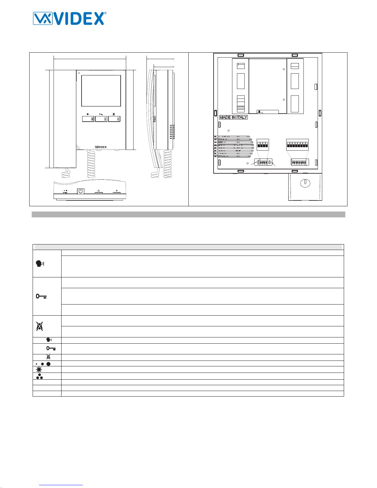
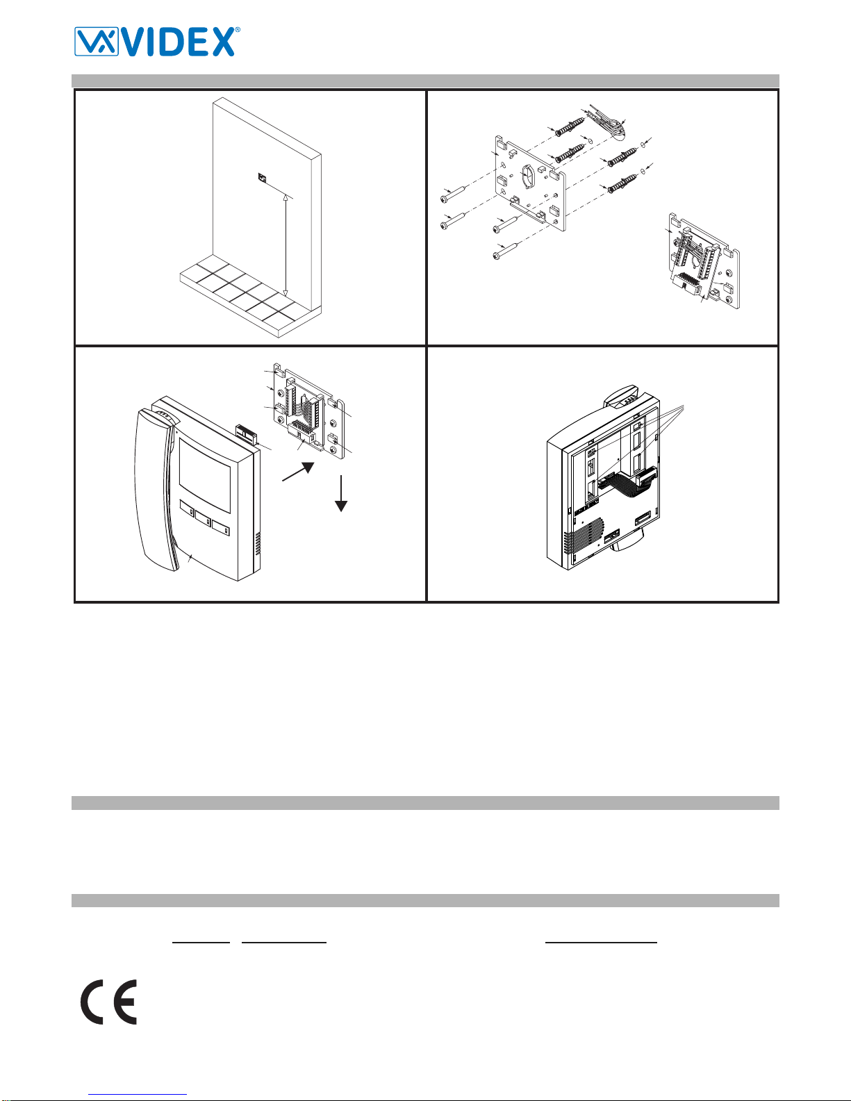
VX2300 2 Wire Video Digital System
PrtCode:VX2300_3_1.doc – Pag.28 04/09/2012 Rev.3.1
PROGRAMMING
The videophone setup consists of the following settings:
- Number of Rings;
- Melody selection;
- Privacy duration;
- Unit address (1..127, switches 1 to 7 of SW1);
- Bus Termination (open or close, switch SWCH1);
- Intercommunication mode (between apartments or within apartment switch 1 of SW3);
- Extension address (1..4, switches 2,3 of SW3);
- Slave mode (switch 4 of SW3);
The programming of the number of rings, melody and privacy duration are carried out through the videophone push buttons, all other settings are car-
ried out on the two dip-switch banks (SW1 and SW3) on the rear side of the video monitor (all the settings can be done without open the videophone).
Except the number of rings programming, it is necessary to remove temporary the power supply after making any other programming
changes.
NUMBER OF RINGS, MELODY SELECTION AND PRIVACY DURATION
To make these settings, it is necessary to pick up the handset first when the system is in stand-by.
Number of rings
Keep pressed the button “ ” until the two LEDs and .are switched on.
Press the “ ” button for a number of times corresponding to the required number of rings to set. A beep confirms each time the button is pressed.
Once set the required number of rings, wait approx 5 seconds of idle time that the two LEDs switch off. The new value is stored.
Melody selection
Keep pressed the button “ ” until the two LEDs and .are switched on. The unit emits the current selected melody.
Press the “ ” button and keep it pressed to listen the next melody. Repeat the operation until the required melody is found.
Once set the required melody is found, wait approx 5 seconds of idle time that the two LEDs switch off. The new melody is set.
Privacy duration
Keep pressed the button “ ” until the two LEDs and .are switched on.
Press the “ ” button for a number of times corresponding to the required privacy duration to set. Each time the button is pressed, the duration is in-
creased of 15 minutes: to set 2 hours, press the button 8 times.
Once set the required privacy duration, wait approx 5 seconds of idle time that the two LEDs switch off. The new melody is set.
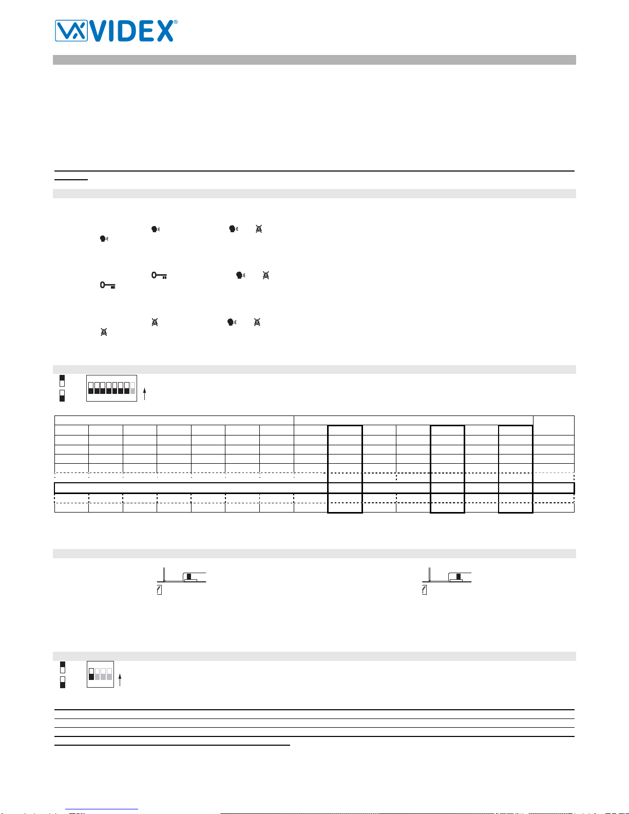
VIDEOPHONE ADDRESS – SW1.1..7
The table above shows how to set the address of the videophone. Considering that ON = 1 and OFF = 0, multiply each
digit for the relevant decimal weight then sum values obtained to get the address: E.g. as highlighted in the table
OFF,ON,OFF,OFF,ON, OFF,ON in binary is equal to 0100101 then multiplying each digit for the relevant decimal weight
you obtain the address that is 37.
Switches Status Binary Code – Decimal Weight Address
7 6 5 4 3 2 1 64 32 16 8 4 2 1
OFF OFF OFF OFF OFF OFF ON 0 0 0 0 0 0 1 1
OFF OFF OFF OFF OFF ON OFF 0 0 0 0 0 1 0 2
OFF OFF OFF OFF OFF ON ON 0 0 0 0 0 1 1 3
OFF OFF OFF OFF ON OFF OFF 0 0 0 0 1 0 0 4
OFF ON OFF OFF ON OFF ON 0 1 0 0 1 0 1 37
ON ON ON ON ON ON ON 1 1 1 1 1 1 1 127
Note
The maximum number of units allowed is 100 but the address of each unit can be a value between 1 and 127.
VIDEOPHONE ADDRESS – SWCH1
Looking at the videophone from the rear side:
SWCH1
SWCH1
Move the switch to the left position to enable the bus termination Move the switch to the right position to disable the bus termination
In case of more units (intercoms, videophones or video monitors) in a parallel connection (bus wires are connected to the terminals of the first unit then
from this to the second and so on up to 4 units max) the BUS termination must be enabled only for the last unit in the chain while on all other units must
be set to disabled.
INTERCOMMUNICATION MODE – SW3.1
This switch establishes the intercommunication mode: in OFF position (default) intercommunication is between units in the same
apartment (same addresses but different extension); in ON position the intercommunication is between units in different apart-
ments (different addresses).
On installations where there are more than one intercom/videophone in the same apartment and intercommunication between different
apartments is required, only one intercom/videophone may be set with this function (SW3.1=ON, SW3.2=OFF, SW3.3=OFF). The other inter-
com/videophones in the apartment must be set for local intercommunication with extension addresses “2-4” (slaves). From the inter-
com/videophone set for intercommunication with other apartments it will be not possible to intercommunicate within the apartment but slave
extensions 2-4 will be able to intercommunicate with each other.
4
3
ON
2
1
=OFF
=ON ON
SW3.1
SW1.1..7
5
4
3876
ON
2
1
=OFF
=ON ON