manuals.online logo
Brands
  1. Home
  2. •
  3. Brands
  4. •
  5. Videx
  6. •
  7. Telephone
  8. •
  9. Videx 3676 User manual

Videx 3676 User manual

74
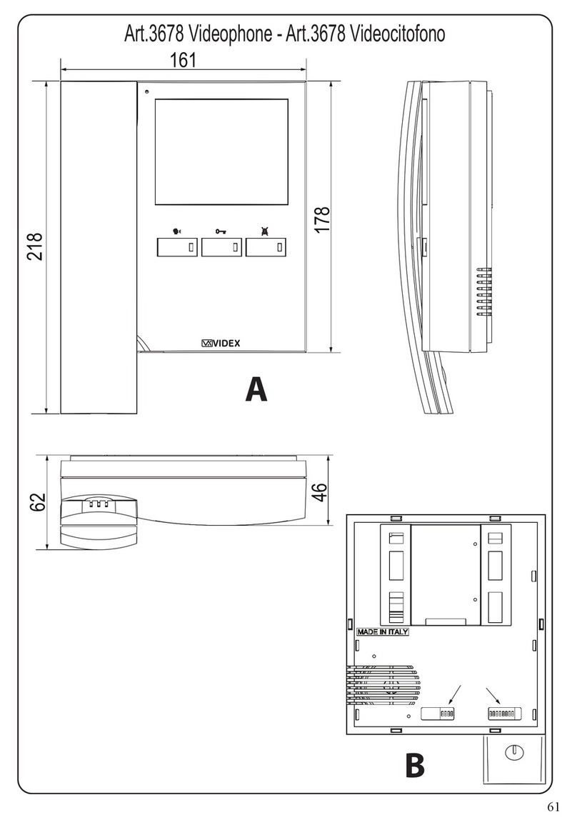
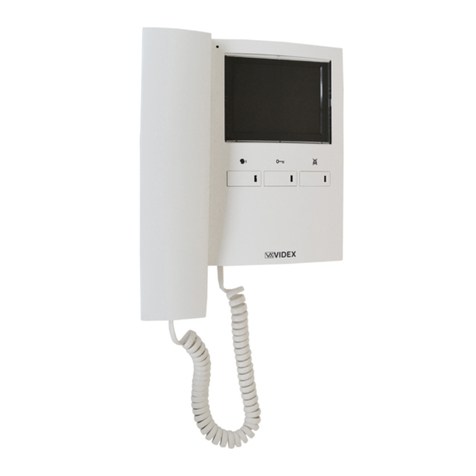
Art.3676 Videophone - Art.3676 Videocitofono
A
B
161
178
218
62
46
678
1235
4
ON
SW1
1234
ON
SW2
123
ON
SW3
VIDEX ELECTRONICS S.p.A. VX2200 “2 WIRE” Bus Digital System
75
ART.3676 VIDEOCITOFONO DIGITALE SERIE 3600
PER SISTEMI DIGITALI VX2200
Descrizione
Videocitofono specifico per il sistema VX2200 con monitor a colori LCD
TFT da 3,5”, pulsanti “auto-accensione”, “apri-porta”, “privacy/servizio” più
3 LED relativi al funzionamento dei pulsanti.
Programmazioni: modo video (coassiale o bilanciato), tipo di suoneria, nume-
ro di squilli e durata della privacy.
Regolazioni: volume suoneria (3 livelli), saturazione e luminosità.
I morsetti di collegamento sono pienamente compatibili con quelli
dell’Art.3678
Pulsanti & Regolazioni - Funzionamento
Pulsante autoaccensione
Ad impianto spento, premere il pulsante per effettuare l’auto-
accensione ed aprire la comunicazione verso il posto esterno
(il relativo LED si accende). Il numero di pressioni del pulsan-
te dipende dall’identificativo del posto esterno che si vuole
accendere.
Pulsante Apri-porta
Premere durante la conversazione per aprire la porta
dell’ingresso dal quale proviene la chiamata. L’apertura
della porta viene confermata da un segnale acustico. Se il
morsetto “DL” è opportunamente collegato, il relativo LED
resta acceso fino a quando resta aperta la porta.
Premere ad impianto spento per chiamare il centralino di
portineria se presente nel sistema.
Pulsante Privacy on/off – Servizio
Con il sistema in stand-by, premere per attivare il servizio
privacy per il tempo programmato: il relativo LED si ac-
cende a segnalare lo stato di attivazione del servizio.
All’arrivo della chiamata, con il servizio attivo, l’unità non
emette alcun segnale acustico. Il servizio si disattiva allo
scadere del tempo programmato o premendo nuovamente il
pulsante.
Durante la conversazione, premere questo pulsante per atti-
vare il servizio secondario: l’uscita ausiliaria viene attivata
e il morsetto “12/ SB” chiude verso massa per circa 2 se-
condi.
Regola il volume della nota di chiamata su 3 livelli (minimo,
medio, massimo).
Regola la saturazione dell’immagine: ruotare verso destra per
aumentare o verso sinistra per diminuire.
Regola la luminosità dell’immagine: ruotare verso destra per
aumentare o verso sinistra per diminuire.
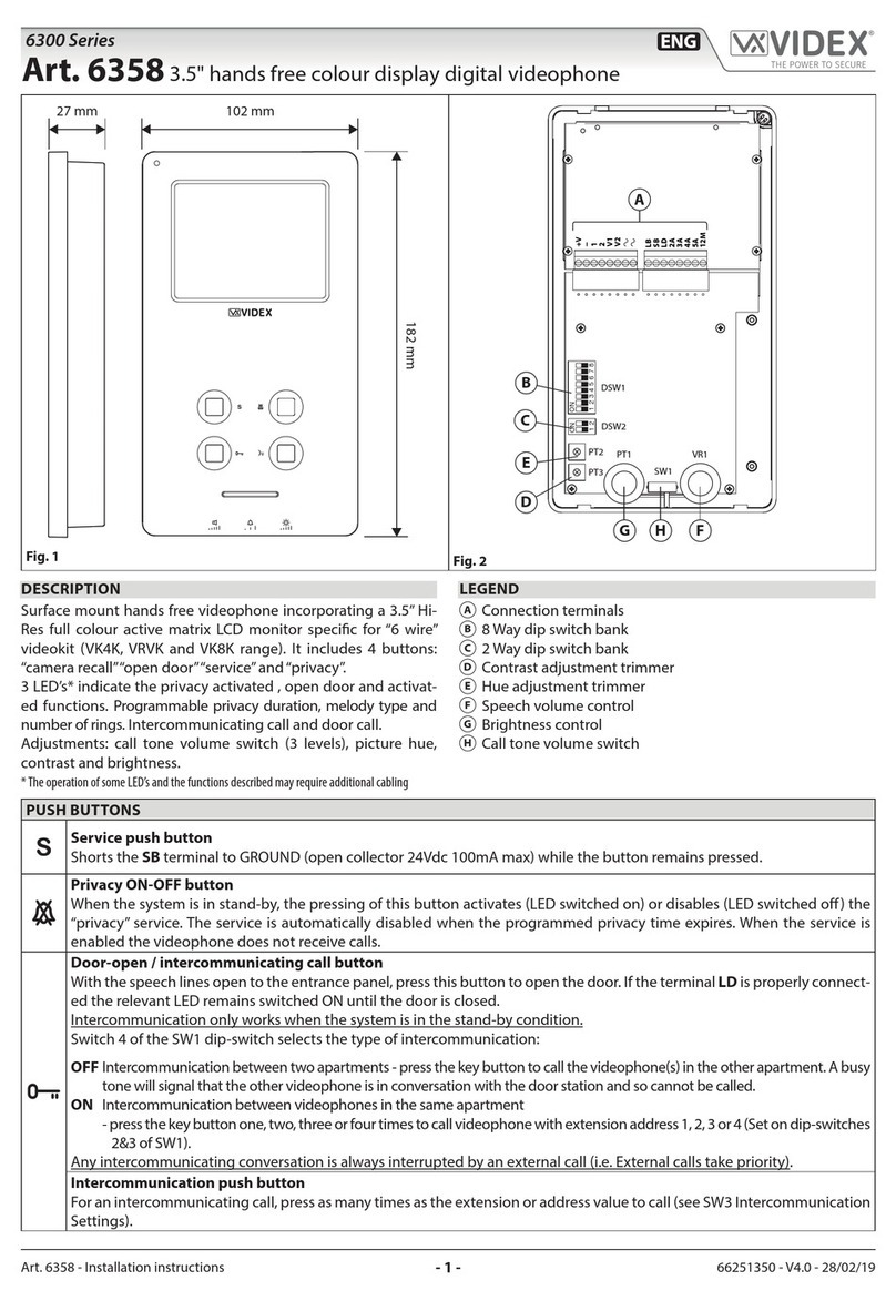
ART.3676 3600 SERIES DIGITAL VIDEOPHONE FOR
VX2200 DIGITAL SYSTEMS
Description
Intelligent videophone for the VX2200 digital system incorporating a 3,5”
full colour active matrix LCD monitor, with “camera recall”, “door open”,
“privacy/service” buttons plus 3 LEDs related to the operation of the but-
tons. Programmable settings: video mode (coax or balanced), melody, num-
ber of rings and privacy duration.
Adjustments: call tone volume (3 levels), hue and brightness.
Connection terminals are compatible with Art.3678
Push buttons & Controls - Operation
Camera Recall
When the system is in standby, (No calls on the system) opera-
tion of this button will open the speech to the door station. The
related LED will illuminate. Press as many time as the ID val-
ue of the door panel to connect to.
Door Open Push Button
During a conversation, operation of this button will release
the door from where the call originated. This will be con-
firmed by an acoustic tone. If terminal “DL” is connected,
the “door open” LED next to the button will also be illumi-
nated.
When the system is in stand-by, a button press will book a
call to the concierge (If available)
Privacy on/off - Service Push Button
When the system is in stand-by, press this button to enable
the service for the programmed time: the related LED will
illuminate to signal the service enabled. During an incom-
ing call, with the service enabled, the device does not emit
any acoustic signal. The service is disabled when the pro-
grammed time expires or pressing again the button.
During a conversation, press this button to enable the auxil-
iary service: by pressing the button terminal “12/SB” is in-
ternally linked to ground for 2 seconds.
Adjusts call tone volume (3 levels): low, medium and high.
Adjusts the picture hue: right rotation to increase, left rotation
to decrease.
Adjusts the picture brightness: right rotation to increase, left
rotation to decrease.
Programmazioni e Regolazioni
Le opzioni programmabili sono:
Suoneria (9 disponibili);
Numero di squilli (3 o 6 default);
Modo Video (coassiale o bilanciato);
Durata privacy (15 minuti – 16 ore o illimitato);
Indirizzo Videocitofono (Phone ID)
Per impostare la suoneria
Con il videocitofono in stand-by, premere e tenere premuto (10 secondi circa)
il pulsante “ ” fino a quando l’unità riproduce la suoneria correntemente
programmata ed emette un bip al termine. Premere nuovamente il pulsante
“” per ascoltare le suonerie disponibili (max 9). Selezionata la suoneria
desiderata, attendere, senza compiere alcuna operazione, circa 5 secondi che
venga emesso un bip. La nuova suoneria è memorizzata.
Per impostare il numero di squilli (6 o 3)
L’impostazione di default è 6 per impostare 3 procedere come segue:
a. togliere l’alimentazione al videocitofono scollegando il cavo flat dalla
scheda di connessione;
b. mettere in corto i morsetti 8 e 9 (segnali “GND” ed “LB”) della sche-
da di connessione;
c. ricollegare il cavo flat e attendere l’emissione di un bip prima di ri-
muovere il corto dai morsetti 8 e 9;
d. per tornare a 6 squilli, procedere alla stessa maniera ripartendo dal
punto (a), ma al punto (c) verranno emessi due bip.
Programming and Adjustments
The programmable settings are:
Melody (9 available);
Number of rings (3 or 6);
Video mode (coax or balanced);
Privacy duration (15minutes – 16 hours or unlimited);
Videophone address (Phone ID);
To set melody
Press and hold (for approx 10 seconds) the “”button until the unit plays
the current programmed melody and emits a beep at the end. Press again the
“”button to listen to the available melodies (maximum 9). Once the se-
lected melody has been reached, wait 5 seconds for a beep. The new melody
will be stored.
To set the number of rings (6 or 3):
Default setting is 6, to set 3 proceed as follows:
a. turn off the videophone by unplugging the flat cable from the PCB
connection board;
b. make a short between terminals 8 and 9 (signals “GND” and “LB”)
of the PCB connection;
c. plug the flat cable onto the PCB connection board and wait for a beep
before removing the short between terminals 8 and 9;
d. to go back to 6 rings, do the same but two beeps will be emitted.
VIDEX ELECTRONICS S.p.A. VX2200 “2 WIRE” Bus Digital System
76
Per impostare il modo video e la terminazione
Il videocitofono può funzionare con il segnale video composito (cavo coas-
siale) o con il segnale video bilanciato (2 fili). Gli switch 1&2 di SW2 per-
mettono di impostare il modo video mentre tramite gli switch 3&4 è possibile
abilitare la terminazione video. In caso di più videocitofoni con una connes-
sione “entra/esci” per il segnale video, la terminazione deve essere abilitata
solo sull’ultimo videocitofono.
To set the video mode
The videophone can operate with either composite video signal (coax cable)
or balanced video signal (two wires). Switches 1 & 2 of SW2 are used to set
video mode while switches 3 & 4 are for video termination. When more vide-
ophone have a pass through connection for the video signal, you must enable
the video termination only for the last videophone.
Modo Video – SW2
Switch 1,2 Modo
Coassiale
Bilanciato
Term. video 75 Ohm – SW2
Switch 3,4 Terminazione
Abilitata
Disabilitata
Video Mode – SW2
Switches 1,2 Mode
Coax
Balanced
75 Ohm Video Term. – SW2
Switches 3,4 Termination
Enabled
Disabled
Per impostare la durata della privacy
La durata della privacy viene impostata tramite il dip-switch a 3 vie SW3.
To set privacy duration
The privacy duration is set by the 3 way dip-switch bank SW3.
Durata Privacy – SW3
SW3 Dip-Switch Durata
1 2 3
off off off Illimitato
on off off 15min
off on off 30min
on on off 1 ora
off off on 2 ore
on off on 4 ore
off on on 8 ore
on on on 16 ore
Privacy Duration – SW3
SW3 Dip-Switch Duration
1 2 3
off off off Unlimited
on off off 15min
off on off 30min
on on off 1 ora
off off on 2 ore
on off on 4 ore
off on on 8 ore
on on on 16 ore
Impostazione indirizzo video/citofono, modo e terminazione video Videomonitor/intercom address, video mode and termination setup
L’indirizzo del citofono/videocitofono è codificato in binario tramite il dip-
switch ad 8 vie situato sul retro dell’unità. Ogni switch corrisponde ad un bit
che può essere a 0 (OFF) o 1 (ON), a ciascun bit corrisponde un peso decima-
le in base alla posizione: Switch 1=decimale 1, 2=2, 3=4, 4=8, 5=16, 6=32,
7=64, 8=128 per impostare l’indirizzo desiderato, mettere ad ON (1) gli
switch la cui somma dei pesi corrisponde al valore dell’indirizzo. Ad esem-
pio, per impostare l’indirizzo 37, mettere ad ON gli switch 1, 3 e 6
(1+4+32=37).
Each intercom is addressed in binary (PHONE ID) using the 8 way
dipswitches located on the rear of the unit. Each switch corresponds to one
bit which can have a value 0 (OFF) or 1 (ON). Each bit corresponds to a
decimal weight depending on the position: Switch 1 = decimal 1, 2=2, 3=4,
4=8, 5=16, 6=32, 7=64, 8=128. I.E. to set the address 37, put switches 1, 3
and 6 on (1+4+32=37).
Switches – Switch Decimal Weight – Peso Decimale Addr.
Indir.
8 7 6 5 4 3 2 1 128 64 32 16 8 4 2 1
OFF OFF OFF OFF OFF OFF OFF ON 0 0 0 0 0 0 0 1 1
OFF OFF OFF OFF OFF OFF ON OFF 0 0 0 0 0 0 1 0 2
OFF OFF OFF OFF OFF OFF ON ON 0 0 0 0 0 0 1 1 3
OFF OFF OFF OFF OFF ON OFF OFF 0 0 0 0 0 1 0 0 4
OFF OFF ON OFF OFF ON OFF ON 0 0 1 0 0 1 0 1 37
ON OFF ON ON OFF ON OFF OFF 1 0 1 1 0 1 0 0 180
VIDEX ELECTRONICS S.p.A. VX2200 “2 WIRE” Bus Digital System
77
Art.3676 - SEGNALI SCHEDA DI CONNESSIONE Art.3676 - PCB CONNECTION BOARD SIGNALS
Descrizione Morsetto
Terminal Description
Ingresso alimentazione video 17÷20Vdc +20V 1
Video power supply 17÷20Vdc
Ingresso alimentazione video 17÷20Vdc +20V 2
Video power supply 17÷20Vdc
Alimentazione video riferimento di massa GND 3
Video power supply ground reference
Alimentazione video riferimento di massa GND 4
Video power supply ground reference
Sincronia V2 segnale video bilanciato (modo seg. video bil.)
Segnale video composito (modo segnale video coassiale) V2/V 5
Balanced video signal V2 sync.(balanced video signal mode)
Composite video signal (coax video signal mode)
Sincronia V1 segnale video bilanciato (modo seg. video bil.) V1 6
Balanced video signal V1 sync.(balanced video signal mode)
Linea BUS L 7
BUS line
Linea BUS riferimento di massa GND 8
BUS line ground reference
Ingresso chiamata locale (attivo basso) LB 9
Local bell input (active low)
Ingresso segnale d’allarme (attivo basso) AL 10
Alarm input (active low)
11
Pulsante di servizio open collector SB 12
Service Push button (close to ground when pressed)
Uscita nota elettronica per suoneria aggiuntiva tipo Art.512A TO 13
Call tone output for extension sounder like Art.512A
14
Uscita +12Vdc per alimentazione distr. video Art.894/894N +VD 15
+12Vdc output to supply the video distributor Art.894/894N
Massa GND 16
Ground
Ingresso alimentazione LED ausiliario (pulsante ) LDO 19
Auxiliary LED ( button) power supply input
Massa GND 20
Ground
Specifiche tecniche
Tensioni d’alimentazione : 17÷20Vdc
Assorbimenti : 250mA Max (on 20Vdc)
Temperatura di Lavoro : -10ºC +50ºC
Technical specification
Working Voltage : 17÷20Vdc
Power Consumption : 250mA Max (on 20Vdc)
Working Temperature: -10ºC +50ºC
VIDEX ELECTRONICS S.p.A. VX2200 “2 WIRE” Bus Digital System
78
Art.3676 Istruzioni di fissaggio a parete Art.3676 Wall mounting instructions
135cm
Fig.1
a
a
a
b
c
c
f
ff
f
g
e
d
bb
b
a
Fig.2
A
B
h
il
m
m
m
m
c
Fig.3
n
Fig.4
Dovendo passare attraverso la fessura “e” (fig.2A) della placca di fissaggio
a parete, consigliamo di canalizzare i conduttori in maniera tale da lasciare
135cm circa tra la parte inferiore della scheda di fissaggio ed il pavimento
finito come mostrato in figura 1;
Appoggiare la piastra di fissaggio “c” alla parete facendo passare il gruppo
di fili “d” attraverso l’apertura “e” della stessa e prendere i riferimenti per i
fori di fissaggio “a” (fig.2A);
Eseguire i fori “a”, inserire al loro interno i tasselli ad espansione “b” e
dopo aver fatto passare il gruppo di fili “d” attraverso l’apertura “e” fissare
la piastra “c” alla parete tramite le viti “f” fornite a corredo (Fig.2A);
Agganciare la scheda di connessione “g” alla placca di fissaggio “c” come
mostrato in figura 2B e procedere alla connessione dei fili alla morsettiera
(in accordo con lo schema fornito) tramite il giravite (lama lato a taglio)
fornito a corredo;
Collegati i fili, agganciare il videocitofono “h” alla piastra “c” come mo-
strato in figura 3:
inserire il connettore “i” del cavo flat che fuoriesce dal retro del vi-
deocitofono nel connettore “l” della scheda di connessione (Fig.3),
avvicinare il videocitofono alla placca di fissaggio facendo corri-
spondere le aperture “n” (Fig.4) ai ganci “m” (Fig.3) quindi spingere
il videocitofono verso il basso fino all’aggancio come suggerito dalle
frecce in figura 3.
Per rimuovere il videocitofono, tenendolo saldamente spingerlo verso
l’alto fino allo sblocco.

Cables must be fed through the opening “e” (Fig. 2A) of the mounting
plate “c”, which should be fitted approximately 135cm from finished floor
level as shown in Fig 1;
Place the mounting plate “c” against the wall feeding the wire group “d”
through opening “e” of the mounting plate and mark the fixing holes “a”
(Fig. 2A)
Drill the fixing holes “a”, insert the wall plugs “b” then with the cables
threaded through opening “e” fix the mounting plate “c” to the wall with
the 4 screws provided “f” (Fig. 2A).
Hook the pcb connection board “g” to the mounting plate “c”as shown in
Fig2B and connect the wires (using the screwdriver provided) to the ter-
minals as shown in the diagram provided;
Once the wires are connected, hook the videophone “h” to the Mounting
plate “c” as shown in Fig. 3.
Connect the Plug “I” on the ribbon cable from the videophone to the
plug “l” on the PCB connection board “g”;
Place the videophone “h” against the 4 hooks “m” on the mounting
plate “c” (in line with the 4 openings “n” on the rear side of the vid-
eophone Fig. 4) and push down as suggested by the pointers in Fig.
3, the videophone will lock into place;
To remove the videophone, hold it firmly and push the unit in an upward
direction until the videophone “h” unlocks from the mounting plate “c”
158
127

Other Videx Telephone manuals

Videx 6758 User manual

Videx

Videx 6758 User manual

Videx 3000 Series User manual

Videx

Videx 3000 Series User manual

Videx 6778 VX2200 User manual

Videx

Videx 6778 VX2200 User manual

Videx 3000 Series User manual

Videx

Videx 3000 Series User manual

Videx 3678 User manual

Videx

Videx 3678 User manual

Videx 6231 User manual

Videx

Videx 6231 User manual

Videx 6300 Series User manual

Videx

Videx 6300 Series User manual

Videx 6200 Series User manual

Videx

Videx 6200 Series User manual

Videx SL5488 Installation instructions

Videx

Videx SL5488 Installation instructions

Videx 4KC Series User manual

Videx

Videx 4KC Series User manual

Videx 6700 Series User manual

Videx

Videx 6700 Series User manual

Videx 6200 Series User manual

Videx

Videx 6200 Series User manual

Videx 3000 Series User manual

Videx

Videx 3000 Series User manual

Videx 3313 User manual

Videx

Videx 3313 User manual

Videx 6200 Series User manual

Videx

Videx 6200 Series User manual

Videx Kristallo KRV7985 User manual

Videx

Videx Kristallo KRV7985 User manual

Videx 3000 Series User manual

Videx

Videx 3000 Series User manual

Videx Kristallo KRV7 Series User manual

Videx

Videx Kristallo KRV7 Series User manual

Videx 3000 Series User manual

Videx

Videx 3000 Series User manual

Videx 6758 User manual

Videx

Videx 6758 User manual

Videx 3311 User manual

Videx

Videx 3311 User manual

Videx 6200 Series User manual

Videx

Videx 6200 Series User manual

Videx 280N1 User manual

Videx

Videx 280N1 User manual

Videx VX2300 User manual

Videx

Videx VX2300 User manual

Popular Telephone manuals by other brands

Panasonic KXDT346 - DIGITAL PROPRIETARY TELEPHONE quick reference

Panasonic

Panasonic KXDT346 - DIGITAL PROPRIETARY TELEPHONE quick reference

Panasonic KX-TS100EXW Service manual

Panasonic

Panasonic KX-TS100EXW Service manual

Ericsson DT360 operating instructions

Ericsson

Ericsson DT360 operating instructions

Jabees Jmusic ALEJMS user guide

Jabees

Jabees Jmusic ALEJMS user guide

Dell Fonality installation guide

Dell

Dell Fonality installation guide

SpectraLink 7532 user guide

SpectraLink

SpectraLink 7532 user guide

Geemarc VisoTempo 200 user guide

Geemarc

Geemarc VisoTempo 200 user guide

JabloCom BTP -06L user guide

JabloCom

JabloCom BTP -06L user guide

RCA 25214RE1 user guide

RCA

RCA 25214RE1 user guide

Tone Commander 6210 user manual

Tone Commander

Tone Commander 6210 user manual

Huawei Mate20 Pro user guide

Huawei

Huawei Mate20 Pro user guide

Cisco IP DECT 6800 Series manual

Cisco

Cisco IP DECT 6800 Series manual

Clarity Giant user guide

Clarity

Clarity Giant user guide

NEC Aspire manual

NEC

NEC Aspire manual

Konnekt Videophone quick start guide

Konnekt

Konnekt Videophone quick start guide

Samsung SGH-Z220 user guide

Samsung

Samsung SGH-Z220 user guide

Unify Atos OpenScape CP110 instructions

Unify

Unify Atos OpenScape CP110 instructions

Invoxia NVX 200 user manual

Invoxia

Invoxia NVX 200 user manual

manuals.online logo
manuals.online logoBrands
  • About & Mission
  • Contact us
  • Privacy Policy
  • Terms and Conditions

Copyright 2025 Manuals.Online. All Rights Reserved.