Videx SMVK1 User manual

Factory - Office
VIDEX ELECTRONICS S.p.A. Via del lavoro,1 63020 MONTEGIBERTO (AP) - ITALY
We recommend
This equipment is installed by a
Competent Electrician, Security or
Communications Engineer
Norme Tecniche
Owner’s Manual
One way, two way
Monofamiliari e Bifamiliari
SMART SERIES VIDEOKITS
VIDEOKIT SERIE SMART

!
!
!
!
!
!
!
!
C
C
C
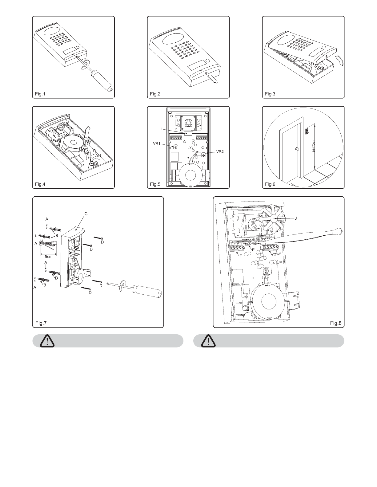
Svitare la vite alla base della placca frontale impiegando un cacciavite a
croce,
Rimuovere la placca frontale facendole prima compiere un leggero
movimento indietro (3-4mm) e quindi sollevandola nella parte inferiore
come mostrato rispettivamente nelle figure 2 e 3.
Rimuovere il supporto per lo speaker (lasciando lo speaker inserito)
tirandolo leggermente verso l’alto come mostrato in figura 4, fino a
raggiungere la condizione di figura 5 (supporto sganciato e rivolto verso il
basso).
Prendere i riferimenti per i fori di fissaggio e per il passaggio dei fili (Rif.H
figura 5), posizionando il posto esterno alle quote mostrate in figura 6
(165-170cm dalla parte superiore del posto esterno al terreno). Qualora i
fili fossero già passati, prendere i riferimenti per i fori di fissaggio tenendo
presente che i conduttori dovranno fuoriuscire dall’apposita fessura del
posto esterno
come mostrato in figura 1.
(Rif.H figura 5). Per collegare agevolmente i conduttori, si
raccomanda di lasciare una lunghezza di 5cm a partire da filo muro (vedi
figura 7).
Eseguire i 4 fori di fissaggio dal diametro di 6mm (Rif.A figura 7); inserire
nei fori i 4 tasselli ad espansione forniti a corredo (Rif.B figura 7);
ricordando di far passare i conduttori attraverso l’apposita fessura (Rif.H
figura 5) del posto esterno, appoggiare l’unità (Rif.C figura 7) al muro e
fissarla con le 4 viti (Rif.D figura 7) fornite a corredo, tramite un cacciavite
a croce.
Fissato a parete il posto esterno, procedere alla realizzazione dei
collegamenti inserendo i conduttori (Rif.E figura 8) nelle apposite
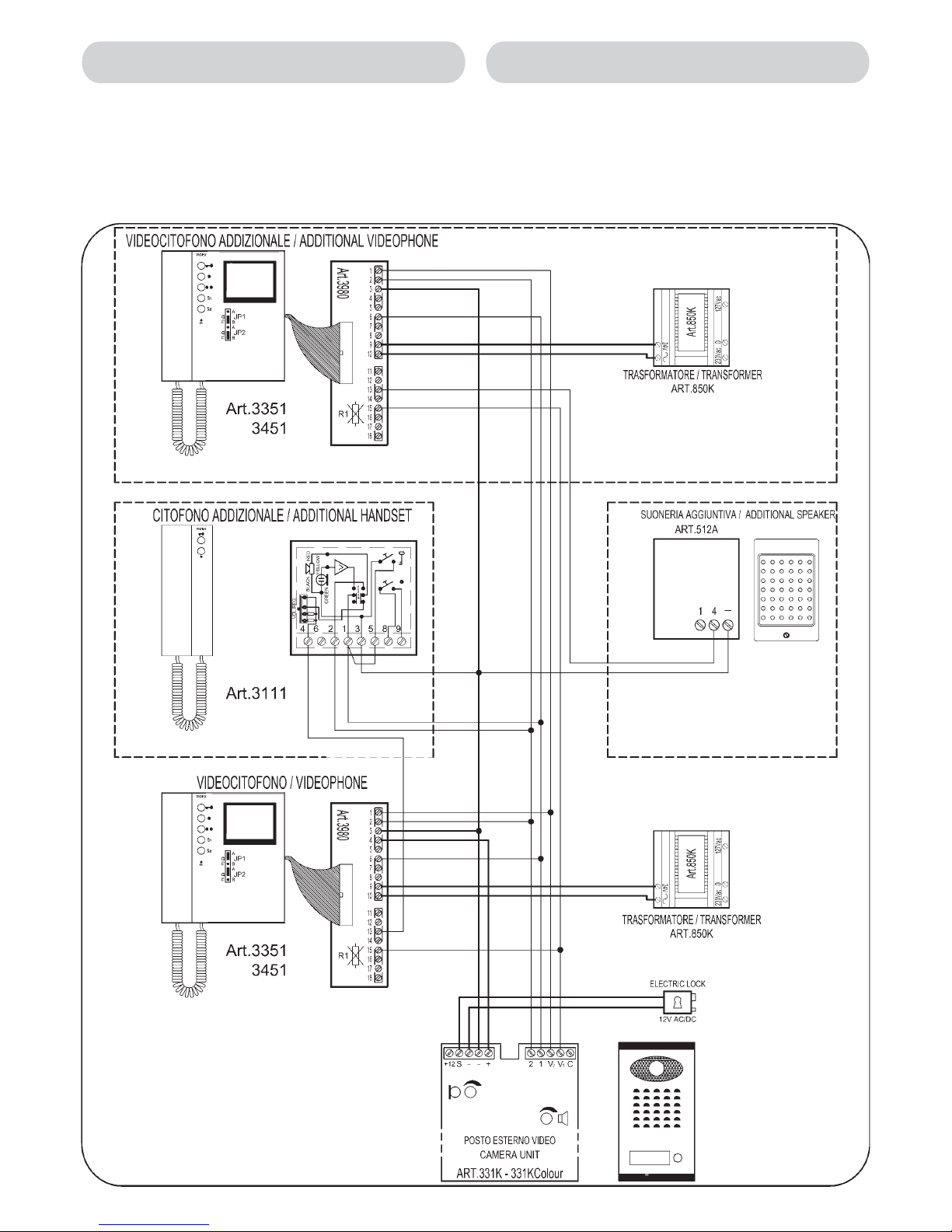
morsettiere (Riff.F e G figura 8). Si ricorda che i collegamenti dovranno
essere eseguiti in base agli schemi di installazione forniti a corredo.
Serrare i conduttori all’interno dei morsetti utilizzando un cacciavite a
taglio. Per l’operazione di inserimento dei fili all’interno dei morsetti si
consiglia l’utilizzo di apposite pinzette (Figura 8).
Eseguiti i collegamenti, ricollocare il supporto per lo speaker nel suo
alloggiamento (condizione di figura 4), quindi procedere al collaudo
dell’impianto ed alla regolazione del brandeggio della telecamera. Per
regolare il brandeggio muovere delicatamente la telecamera secondo le
direzioni mostrate in figura 8 (Rif.J).
Terminato il collaudo, chiudere il posto esterno fissando la placca frontale.
Per fissare la placca frontale:
posizionarla come mostrato in figura 3 (lasciando circa 3-4mm tra la
parte superiore della placca e la superficie di contatto con la base
porta componenti) e successivamente avvicinarla completamente
alla base compiendo un movimento in senso contrario a quello della
freccia di figura 3;
spingere la placca leggermente verso l’alto, compiendo un
movimento in senso contrario a quello della freccia di figura 2, fino a
portarne la parte superiore a contatto con la base porta componenti;
avvitare la vite alla base della placca frontale ruotando il cacciavite in
senso inverso a quello della freccia di figura 1.
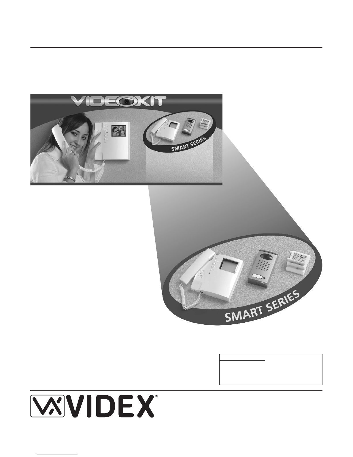
I videokit SMVK1 sono forniti con i videocitofoni della
serie 3000 ed il posto esterno Art.331K. Quest’ultimo ha
subito degli aggiornamenti
nel design, nell’elettronica e nella meccanica
che gli hanno conferito una maggiore resistenza agli
agenti atmosferici. Anche il meccanismo di brandeggio
della telecamera è stato modificato aumentandone
l’angolo di escursione (10 Gradi) e la possibilità di
movimento sia in senso verticale che orizzontale; questo
consente di regolare una buona inquadratura anche
quando il posto esterno deve essere installato in punti
critici (zone esposte al sole, nascoste ecc.).
Il kit (monofamiliare) è composto da:
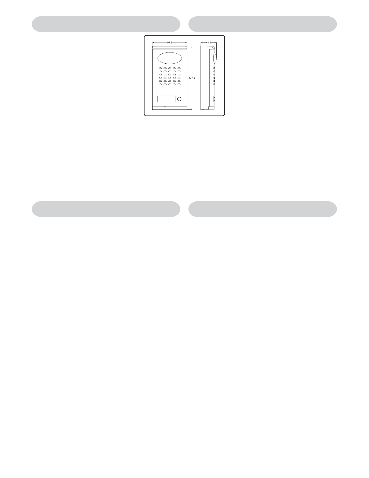
Nr.1 - Unità di ripresa. Incorpora una
telecamera CCD auto focus di alta qualità completa
di LED per l’illuminazione agli infrarossi (nella
versione colori i lED sono ad emissione di luce bianca); la circuiteria di
amplificazione audio ed il portiere elettrico (dimensioni del posto esterno
come da disegno - quote in mm).
Nr.1 - Videocitofono Bianco & Nero con schermo piatto da 4”.
Nr.1 - Trasformatore di alimentazione in contenitore DIN 5
moduli - tipoA. Primario 127-230Vac, Secondario 24Vac-1,6A.
La versione a colori prevede l’unità di ripresa al
posto della ed il videocitofono a colori con schermo piatto TFT
, al posto del . La placca frontale del posto esterno è
disponibile in 2 finiture: Bianco e Grigio (/W o /G dopo il codice).
(rispetto ai precedenti posti
esterni)
La versione con memoria video prevede l’
(videocitofono Bianco & Nero con schermo piatto da 4” e memory board) al
posto del e l’ (alimentatore in contenitore DIN 8 moduli -
tipo A con doppia tensione di uscita 24Vac 1,6A e 12Vdc 0,2A per
l’alimentazione della memory board) al posto dell’ .
SMVK1
Art.331K
Art.3351
Art.850K
CSMVK1 Art.331KColour
331K
Art.3451 3351
-
-
-
SMVK1/MV Art.3551
3351 Art.850K/MV
850K
2
SMVK1, SMVK1/MV, CSMVK1 Easy Videokit B&W, con MEMORIA VIDEO, a COLORI
SMVK1, SMVK1/MV, CSMVK1 Easy Videokit B&W, with MEMORY BOARD, COLOUR
ISTRUZIONI PER L’INSTALLAZIONE DEL POSTO ESTERNO
MOUNTING INSTRUCTIONS OF THE OUTDOOR STATION
The new videokit SMVK1 is supplied with the 3000 series
videophone and the new more compact outdoor station
Art.331K. The new outdoor station (Surface mount only)
has been improved in a number of ways for better
endurance to the weather. The mechanism to adjust the
viewing angle has been changed to allow a larger angle
(10 Degree) than before and to allow horizontal and
vertical motion of the camera; This enable an adjustment
to the picture when the outdoor station is installed in
critical areas (areas exposed directly to the sun light,
hidden areas etc.).
The (one way videokit) is comprised of:
- Outdoor Station. It incorporates a
high quality auto iris lens CCD camera B&W, LEDs
for infrared illumination (white light LEDs for colour
version), audio amplifiers and one call button (outdoor station size as in
the drawing - unit mm).
- Videophone with a 4” B&W flat screen monitor.
- Power transformer in a type A 5 module DIN box;
primary: 127 and 230Vac, secondary 24Vac 1,6A.
SMVK1
Nr.1 Art.331K
Nr.1 Art.3351
Nr.1 Art.850K
-
-
-
The uses the (a videophone with a 4” flat screen
monitor B&W plus the memory board) instead of the Art.3351 and the
(Power Supply in a type A 8 module DIN box with 2 output
voltages: 24Vac 1,6A and 12Vdc 0,2A for memory board supply) instead of
the Art.850K.
The uses the (a videophone with a colour 4” TFT flat
monitor) instead of the and the colour outdoor station
instead of the .
The front plate is available in two different finishes: white and grey (put /W or
/G after the product code).
SMVK1/MV Art.3551
Art.850K/MV
CSMVK1 Art.3451
Art.3351
Art.331KColour Art.331K
!
!
!
!
!
!
!
!
C
C
C
Unscrew the screw at the bottom of the front plate using a Phillips
screwdriver as shown on figure 1.
Gently slide the front plate down (3-4mm) and then raise it at the bottom as
shown on figures 2 and 3.
Extract the speaker housing (leaving the speaker inside it) lifting it up
gently as shown on figure 4 until the speaker housing is as shown in figure
5 (speaker bracket down).
Place the outdoor station against the wall (165-170 Cm between the top of
the outdoor station and the floor level as shown on figure 6) and mark the
fixing holes (Ref.A figure 7) for the four wall plugs (Reff.B figure 7) and the
hole for the cables with reference to the relevant opening on the outdoor
station (Ref.H figure 5). For ease of connection, the cables should be at
least 5 cm in length from the wall (see figure 7). If the cables are placed,
mark the holes feeding the wires through the outdoor station opening
(Ref.H figure 5).
Make the four fixing holes (Ref.A figure 7 - 6mm n); put inside the holes
the four wall plugs provided (Ref.B figure 7);place the outdoor station
against the wall feeding the cables through relevant opening (Ref.H figure
5) and then fix it to the wall with the four screws provided using a Phillips
screwdriver.
After the outdoor station is fixed to the wall, make the connections by
putting the cables (Refer figure 8) into the relevant terminals (Refs. F and
G figure 8). The connections must be made as per the installation diagram
provided. Fix the wires inside the terminals using a terminal screwdriver.
For ease of connection we suggest using tweezers to locate the cables
into the terminals (see figure 8).
After the system test, Refit the outdoor station front plate. Fix the front
plate as follows
Place the front plate over the outdoor station as shown on figure 3
(leaving 3-4mm between the top of the plate and the outdoor station)
then move the bottom of the plate in the opposite direct to the arrow
in figure 3 bring the plate towards the back box.
Slide the plate upwards in the opposite direction to figure 2.
Fix the plate using the relevant screw.
After the connections are made, put the speaker back with its bracket (it
should go back as shown on figure 4) then test the system and adjust the
viewing angle moving the camera slightly to the direction required (Ref. J
figure 8).

La realizzazione dell’impianto deve essere eseguita nel rispetto delle vigenti
normative nazionali, in particolare si raccomanda di:
Collegare l’impianto alla rete elettrica tramite un
che abbia una distanza di separazione del
contatto di almeno 3mm per ciascun polo e che sia in grado di disconnettere
tutti i poli simultaneamente;
Il deve essere posizionato in un
luogo tale da consentirne un facile accesso in caso di necessità.
Rimuovere i coperchi copri-morsetti svitando le relative viti e tirandoli verso
l’alto;
Fissare l’alimentatore su barra DIN o direttamente a parete utilizzando le viti
ed i relativi tasselli ad espansione forniti a corredo;
Togliere la tensione di rete tramite il dispositivo sopra indicato ed eseguire le
connessioni come previsto dagli schemi proposti (la connessione verso la
rete va effettuata in base alla tensione disponibile 127 o 230Vac).
Verificare che non vi siano errori di connessione e che i fili siano ben serrati
nei morsetti;
Inserire a scatto i coperchi copri-morsetti e fissarli tramite le relative viti;
Eseguiti tutti i collegamenti, dare tensione all’impianto.
·
·
-
-
-
-
-
-
dispositivo di
interruzione omnipolare
dispositivo di interruzione omnipolare
Installazione dell’alimentatore
The system must be installed according to national rules in force, in particular
we recommend to:
Connect the system to the mains through an which
shall have contact separation of at least 3mm in each pole and shall
disconnect all poles simultaneously;
The shall be placed for easy access and the switch
shall remain readily operable.
Remove the terminal side covers by unscrewing the retaining screws;
Fix the power supply to a DIN bar or directly to the wall using two expansion
type screws;
Switch off the mains using the circuit breaker mentioned above and then
make the connections as shown on the installation diagrams;
Check the connections and secure the wires into the terminals;
Replace the terminal covers and fix them using the relevant screws;
When all connections are made, restore the mains.
·
·
-
-
-
-
-
-
all-pole circuit breaker
Power Supply Installation
CONNECTION TO MAINS AND
POWER SUPPLY MOUNTING INSTRUCTIONS
COLLEGAMENTO ALLA RETE ELETTRICA ED
INSTALLAZIONE DELL’ALIMENTATORE
3

A
B
B
B
B
D
E
E
E
E
F
Fig.9
G
H
C
Fig.10
I
L
A
M
F
N
N
N
N
O
Piano terra finito
Finished Floor
Piastra di fissaggio Videocitofono
Mounting Plate
135cm
Quote in cm
Size in cm
Fig.11
A
Mounting plate installation and PCB
connections.
A
fig.11
B
fig.9 C fig.9
D fig.9
C
B
DA
E fig.9
F A fig.9
G-H
F fig.9
fig.10
Installing the Videophone onto mounting plate
fig.10 L
AI
fig.10
M
F
LN
A
O fig.10
O
Notes
!
!
!
!
!
!
!
!
Place the mounting plate against the wall as
shown in (135cm from floor level); and
mark the fixing holes for the four wall plugs
( ) and for the back box if used ( )
which must be flushed into the wall in line with
the opening as shown in .
Once the back box is flushed into the wall (if used), drill the four
fixing holes and insert the wall plugs . Thread the cables through
the opening and fix the mounting plate to the wall with the 4
screws ( ), using a Philips screwdriver.
Fit the PCB against the mounting plate as shown in ; insert
the wires (As short as possible) into terminals . Secure them
using a terminal screwdriver.
Unclip the PCB ( ), rotate it 90º anticlockwise and fit it into its
housing as shown in .
As shown in , move the videophone close to the mounting
plate so that the ribbon cable will reach the connector .
As shown in , connect the female plug on the ribbon cable I
coming from the videophone to the male plug connector on the
PCB .
Place the videophone against the 4 hooks on the mounting
plate and push down: the videophone will automatically lock into
place using clasp as shown in .
To remove the videophone from the wall, push the clasp in the
direction of the wall with a screwdriver and at the same time push
the videophone upwards.
We recommend using a back box in order to contain excess wire
behind the back plate.
The wires must be connected to the terminals as shown on the
relevant wiring diagrams.
(1)
(2)
(1)
(2)
Applicazione a muro della piastra di
fissaggio e collegamenti scheda di
connessione.
A
fig.11
B
fig.9
C fig.9
D fig.9
C
B
D A E fig.9
FA
fig.9
GH
F fig.9
fig.10
Applicazione del Videocitofono alla piastra
fig.10 L A
I
fig.10 I
MF
LNA
fig.10
O
Note
!
!
!
!
!
!
!
!
Appoggiare al muro la piastra di fissaggio
come indicato in (135cm da terra);
prendere i riferimenti dei quattro fori per
l’inserimento dei 4 tasselli ad espansione
( ) e, nel caso si impieghi, prendere il
riferimento per la scatola da incasso ( ),
che dovrà essere murata in posizione centrale rispetto all’apertura
, al fine di agevolare il passaggio dei fili come mostrato in .
Murare (se impiegata) la scatola da incasso , eseguire i 4 fori
ed inserire i tasselli ad espansione . Passare i cavi nell’apertura
e fissare la piastra con le 4 viti ( ), utilizzando un
cacciavite a croce.
Appoggiare la scheda di connessione sulla piastra come
mostrato in ; inserire i fili (che devono essere più corti
possibile) nelle morsettiere ed e serrare con un cacciavite a
taglio.
Fissati i fili, sfilare la scheda di connessione ( ), ruotarla di
90º in senso antiorario ed infilarla nella propria sede come
mostrato i n .
Avvicinare, come da , il videocitofono alla piastra per
agevolare la connessione del flat .
Come mostrato in inserire il connettore del flat , che
fuoriesce dalla parte posteriore del videocitofono, nel connettore
della scheda di connessione .
Facendo corrispondere le 4 fessure presenti sulla base del
videocitofono con i 4 incastri della piastra , appoggiare il
video sulla piastra e spingerlo verso il basso fino allo scatto,
compiendo un movimento come mostrato dalle frecce in .
Per rimuovere il videocitofono, spingere con un cacciavite a taglio
il dente verso il muro e, contemporaneamente, tirare il
videocitofono verso l’alto.
Si consiglia di utilizzare una scatola da incasso (non in dotazione e
reperibile sul mercato) al fine di contenere l’eventuale lunghezza
eccedente dei fili.
I collegamenti alla morsettiera devono essere eseguiti rispettando
gli schemi forniti a corredo del videocitofono (per applicazioni
differenti da quelle degli schemi standard, rivolgersi al proprio
rivenditore).
(1)
(2)
(1)
(2)
4
Art.3351, 3451, 3551
Videophones Mounting Instructions
Istruzioni di montaggio per
i Videocitofoni Art.3351, 3451 e 3551

NOTA IMPORTANTE
Per le connessioni Video e quelle audio, suggeriamo di utilizzare delle
coppie di fili intrecciati: una coppia per la linea video (morsetti “ ” e “ ”,
segnali “ ” e “ ”) ed una coppia per quella audio (morsetti “ ” e “ ”,
segnali “ ”ed “ ”).
2 fili da 1 mm (e 2 fili 0,35mm con l’alimentatore Art.850K/MV nel kit EVK-
1/MV).
fino a 50m : tutti i fili da 0.35 mm .
da 50 a 100m : fili+e-da0.75 mm ; tutti gli altri da 0.5 mm .
da 100 a 200m : fili+e-da1.5mm; tutti gli altri da 0.75 mm .
fino a 50m : fili + e - da 0.5 mm ; tutti gli altri 0.35 mm .
115
V2 V1 2 6
21
Dal trasformatore al videocitofono max 20m:
Dal videocitofono al posto esterno:
per SMVK, SMVK/MV
per il CSMVK
22
2
22
22
22
IMPORTANT NOTE
Video connections and Audio connections must be wired in twisted pair : pair
the video lines (terminals “ ” and “ ” signals “ ” and “ ”), pair the audio
lines (terminals “ ” and “ ” signals “ ” and “ ”)
2 wires 1 mm (plus 2 wires 0,35 mm with power supply Art.850K/MV in ).
up to 50 mt : all wires 0.35 mm .
from 50 to 100 mt : wires + and – 0.75 mm ; other wires 0.5 mm .
from 100 to 200 mt : wires + and – 1.5 mm ; other wires 0.75 mm
up to 50 mt : wires + and – 0.5 mm ; other cables 0.35 mm .
from 50 to 100 mt : wires + and – 1 mm ; other cables 0.5 mm .
from 100to 200 mt : wires + and – 2 mm ; other cables 0.75 mm .
115 V2V1
26 21
Between transformer and videophone 20 mt max:
Between videophone and outdoor station:
For SMVK, SMVK/MV
For CSMVK
22
2
22
22
22
22
22
Tensioni di alimentazione
Assorbimento a riposo
Assorbimento massimo in funzione
Temperatura di lavoro
Videocitofono : 22-24Vac
Memory Board (solo perArt.3551) :12Vdc (+1V -4V)
Videocitofono :100mA
Memory Board (solo perArt.3551) :180mA
Videocitofono / Videophone :1,4AMax
Memory Board (solo perArt.3551) :180mA
:-10 +50 Cº
Sia i videocitofoni Art.3351, 3451 e 3551 che i posti esterni 331K e
331KColour sono pienamente compatibili con i precedenti kit della serie VK6
e VK6N.
Working Voltages
Stand-by absorption
Max absorption on call
Working Temperature
Videophone :22-24Vac
Memory Board (only for Art.3551) :12Vdc (+1V -4V)
Videophone :100mA
Memory Board (only for Art.3551) :180mA
Videophone :1,4A Max
Memory Board (only for Art.3551) :180mA
: -10 +50 Cº
The videophone models 3351,3451,3551 and the outdoor stations 331K
and 331KColour are fully compatible with all previous VK6 and VK6N kits.
La indica i segnali (e le relative denominazioni) presenti sulla
morsettiera della scheda di connessione Art.3980 per i videocitofoni
Art.3351, 3451 e 3551.
Tabella 1 Table 1 shows the videophones Art.3351,3451,3551 connections (and
signal name) relevant to the terminals of the PCB connection Art.3980 .
SEGNALI SIGNALS
Tabella1/Table 1
PCB conn.
Art.3980
Signal
Names
Segnali / Signals
Ingresso segnale video sinc.+.
Comando per accensione videocitofono.
1V2
Video Input +sync.
Videophone recall command.
Ingresso fonia.
Comando per autoaccensione - pulsante “ ”
22
Speech input.
Camera recall output - push button “ ”
Massa.
3-
Ground.
Uscita 18-30Vdc per alimentazione posto esterno.
4+
Output 18-30Vdc power supply for outdoor station.
5
Uscita fonia.
Comando per azionamento apertura porta - pulsante “ ”.
61
Speech output.
Door opening output - push button “ ”.
7
8
9
10
Ingresso 22-24Vac per alimentazione videocitofono
Input 22-24Vac power supply videophone.
Comando pulsante “S2”
11 S2 Push button “S2”
12
Uscita nota elettronica di chiamata per citofono o suoneria addizionali.
13 T Output call tone for additional handset or speaker.
Ingresso +12Vdc per alimentazione memory board (solo per Art.3551).
14 +12 Input +12Vdc memory board power supply (only for Art.3551)
Ingresso segnale video sinc.-.
15 V1 Video input -sync.
Comando pulsante “S1”
16 S1 Push button “S1”
Comando pulsante “ ”.
17 Push button “ ”.
Comune pulsanti “ ”,”S1”,”S2”.
18 C Common push buttons “ ”,”S1”,”S2”.
PCB Connection provided
with Art.3980 see Table 1
Scheda di connessione fornita
a corredo dell’Art.3980 vedi Tab.1
R1
*
1
2
3
4
5
6
7
8
9
10
11
12
13
14
15
16
17
18
*
Remove R1 resistor
Rimuovere la resistenza R1
5
COMPATIBILITÀ CON I KIT VK6 E VK6N PREVIOUS VK6, VK6N KITs COMPATIBILITY
SPECIFICHE TECNICHE TECHNICAL SPECIFICATIONS
SEZIONE DEI FILI WIRES & SECTIONS

If the system doesn’t work, make the following preliminary tests:
Check the mains power between terminals 230 Vac (or 127 Vac) and 0 of power
transformer Art.850K.
Check voltage output “24 Vac” on transformer: if there is no voltage output, check
that the fuse 1,6A is not blown before replacing a fuse with another of same value be
sure there are no short circuits or overloads.
Check the voltage between terminals + and -: it must be between 18 and 30 Vdc.
Check , on the outdoor station and on the videophone PCB connection, that each
cable is correctly plugged on the relevant terminal.
In case of other defects, check signals and tensions on the following terminals (referred
to ground terminal -), depending on various situations:
+12V in standby.
+0,6V and audio signal, with handset picked up: audio outdoor station
microphone towards handset earphones.
+12V in standby.
0V with door opening button pressed.
+4V and audio signal, with handset picked up: audio from handset
microphone towards outdoor station loudspeaker.
0V in standby.
Video signal, sync. after call or recall.
(videophone power on signal)
0V in standby.
Video signal, sync. after call or recall.
0V in standby.
(Art.3980) during reception of the call.
during electric lock opening.
!
!
!
!
Terminal State
2
1
V2
V1
T/13
S
+3,5V with recall button pressed.
·
!
!
!
!
!
!
>
>
!
>
>
Eseguire tutti i collegamenti secondo gli schemi proposti.
Verificare la corretta esecuzione delle connessioni e dare tensione all’
impianto.
Controllare che i led di illuminazione del porta cartellino siano accesi.
Premere il pulsante di chiamata (Rif.3 Pag.7):
se l’installazione è stata eseguita correttamente, l’altoparlante interno al
videocitofono (con cornetta agganciata) emetterà una nota modulata per 3
sec (regolare il volume della nota agendo sul relativo controllo
) e contemporaneamente il monitor mostrerà l’immagine ripresa
dalla telecamera.
Ottimizzare la qualità dell’ immagine agendo sulle slitte di regolazione
contrasto e luminosità (rif. 9 e 10 pag.7).
Verificare la qualità audio (di fabbrica i circuiti sono tarati per un ottimo
livello audio) del sistema sollevando la cornetta per conversare con il
posto esterno e, se necessario, eseguire le regolazioni dei volumi tramite i
trimmer presenti sul retro di quest’ultimo:
agire sul trimmer (Fig.5 Pag.3) per regolare il volume dello speaker
del posto esterno;
agire sul trimmer per regolare il volume del microfono
del posto esterno.
Nel caso si sentano dei fischi (effetto Larsen), diminuire il livello dei volumi.
Premere il tasto per aprire la serratura elettrica.
Nei verificare il corretto funzionamento della
memoria video (incorporata nel videocitofono) facendo riferimento alle
relative istruzioni fornite a corredo.
Il videocitofono si spegne riagganciando la cornetta o trascorsi 2 minuti dalla
ricezione della chiamata.
L’auto-accensione può essere:
audio e video sollevando la cornetta;
solo video premendo il tasto “ ”.
Dopo aver effettuato tutti i controlli, occorre completare il montaggio del
posto esterno.
Rif.11
Pag.7
(Fig.5 Pag.3)
VR2
VR1
VIDEOKIT Art.SMVK/MV
·
Se si manifestano problemi di funzionamento, si consiglia di effettuare i seguenti
controlli preliminari:
verificare che sia presente la tensione di rete sui morsetti 230Vac (o 127Vac) e 0 del
trasformatore di alimentazioneArt.850K.
Verificare la tensione di uscita “24Vac” del trasformatore: l’eventuale assenza di tale
tensione può essere causata dall’interruzione del fusibile da 1,6A; prima di sostituire
il fusibile interrotto, con uno avente le stesse caratteristiche, accertarsi che non ci
siano cortocircuiti o un sovraccarico.
Verificare la tensione fra i morsetti + e -: dovrebbe essere compresa fra 18 e 30Vdc.
Verificare, sia sul posto esterno che sulla scheda di connessione, che i fili siano
inseriti nei morsetti giusti e che siano serrati saldamente.
Se i precedenti controlli sono andati a buon fine, ma continuano a manifestarsi dei
difetti, si consiglia di procedere alla misurazione delle tensioni ed alla verifica dei
segnali presenti sui morsetti durante il funzionamento. Le misurazioni vanno eseguite
in riferimento al morsetto di massa “ ”:
+12V a riposo.
+3,5V con pulsante “auto-accensione” premuto.
+0,6V e segnale fonico, con cornetta sollevata ( fonia dal microfono
posto esterno verso auricolare cornetta).
+12V a riposo.
0V con pulsante “apri-porta” premuto.
+4V e segnale fonico, con cornetta sollevata (fonia da microfono
cornetta verso altoparlante P.E.)
0V a riposo.
Segnale video sinc. dopo la chiamata o autoaccensione
(comando per accensione videocitofono).
0V a riposo.
Segnale video sinc. dopo la chiamata o autoaccensione.
0V a riposo.
(Art.3980) durante la ricezione della chiamata.
Durante l’apertura della serratura elettrica.
!
!
!
!
-
Morsetto Stato
2
1
V2
V1
T/13
S
·
!
!
!
!
!
!
>
>
!
>
>
Carry out connections accurately using the wiring diagram provided.
Be sure that all connections are well made and then power up the system.
Check that card name illumination LEDs are switched on.
Press call button (Ref.3 Page.7):
an electronic tone will be heard from the videointercom (the handset must
be replaced) for 3 seconds (During this time adjust the call tone volume by
operating the relevant control Ref.11 Page.7), at the same time the
videophone will light up and the picture will appear.
Set the Contrast and the Brightness to adjust the quality of picture, by
operating the relevant controls (Ref.9 and 10 Page 7).
Check the audio quality(all circuits are adjustable for optimum audio
quality) by picking up the handset and talking with the outdoor station. If
necessary adjust the volume levels by operating trimmers that are located
on the back of the outdoor station:
operate trimmer (Fig.5 Page 3) to adjust the speaker volume of
outdoor station.
operate trimmer (Fig.5 Page 3) to adjust the microphone volume of
outdoor station.
If it is necessary, reduce volumes to avoid feedback.
Press button to operate the electric lock.
In the Check the memory board functions
correctly by making reference to the relevant enclosed instructions.
The videophone switches off when the handset is replaced or after 2 minutes
of conversation.
The recall can be:
audio and video by picking up the handset;
only video by pressing the button “ ”.
When all tests have been completed, it is necessary to complete the outdoor
station mounting.
VR2
VR1
VIDEOKITS Art.SMVK/MV
·
COLLAUDO IMPIANTO SYSTEM TESTING
RICERCA GUASTI TROUBLESHOOTING GUIDE
6

1. Obiettivo telecamera CCD completa di 6 LED agli infrarossi (o LED
ad emissione di luce bianca per il CEVK) per l'illuminazione notturna:
consentono, in totale assenza di luce, di vedere un visitatore fino ad
una distanza di 80cm. Per distanze superiori è necessaria una
illuminazione supplementare.
2. Portacartellino retroilluminato.
3. Tasto di chiamata.
4. Microfono e relativo trimmer di regolazione del volume.
5. Loudspeaker for audio reception; trimmer for volume adjustment.
1. Cornetta.
2. Schermo.
3. TastoApriporta.
4. TastoAutoaccensione.
5. Tasto di Servizio.
6. Tasto di Servizio.
7. Tasto di Servizio.
8. LED “ON”.
9. Regolazione Contrasto.
10. Regolazione Luminosità.
11. Regolazione Volume nota di chiamata.
12. Ponticelli mobili e per chiusura impedenza a 75 .
13. Scheda di connessione.
JP1 JP2 W
1. Handset.
2. Screen.
3. Door Opening Button.
4. Video Recall Button.
5. Service Button.
6. Service Button.
7. Service Button.
8. “ON” LED.
9. Video contrast image adjustment.
10. Video brightness image adjustment.
11. Electronic call tone volume control.
13. PCB connections.
12. and jumpers to close impedance at 75JP1 JP2 W.
1. CCD camera lens complete with 6 infrared illumination LEDS: they
allow you to see the visitor up to 80 cm in a completely dark place;
additional illumination is required in case of larger distances.
2. Illuminated card name.
3. Call button.
4. Microphone; trimmer for sensitivity adjustment.
5. Loudspeaker for audio reception; trimmer for volume adjustment.
SCHEMA DI INSTALLAZIONE SMVK1 CSMVK-1
Videokit Bianco & Nero e a Colori
WIRING DIAGRAM SMVK1 CSMVK1
Videokit B&W or Colour
7
VIDEOPHONE: ART.3351 OR 3451VIDEOCITOFONO: ART.3351 OR 3451
POSTO ESTERNO: 331K O 331KColour OUTDOOR STATION: 331K OR 331KColour

SCHEMA DI INSTALLAZIONE SMVK1/MV
Videokit con memoria video
WIRING DIAGRAM SMKV1/MV
Videokit with memory board
Lo schema mostra come realizzare un impianto a 2 ingressi e come collegare un
videocitofono addizionale (non fornito nel kit) in parallelo. Per il servizio di “auto-
accensione” sull’ingresso desiderato, occorre premere prima il pulsante “ ” (viene
acceso l’ingresso dal quale è arrivata l’ultima chiamata) quindi il per
l’ingresso “ ” o “ ”.
·
pulsante “ ”
il pulsante “ ” per l’ingresso
··
ABS1
Collegando in parallelo altri videocitofoni (max 3 in totale) ricordare di impostare
i jumper JP1 e JP2 dei videocitofoni intermedi in posizione A e lasciare in
posizione B quelli dell’ultimo videocitofono in ordine di collegamento.
The diagram below shows a 2 entrance video entry system with an additional
videophone (not provided with the kit). The “ ” push button enable the camera recall
from the last entrance from which the call was made. After the system is switched on by
pressing the “ ” push button, the “ ” push button enables the camera recall from
entrance “ ” and the “ ” push button enables the camera recall from entrance “ ”.
·
···
ABS1
Installing one or more videophones (max 3 total) in a parallel connection leave
JP1 and JP2 of the last videophone in B position and on all other videophones put
the two jumpers in Aposition.
SCHEMA DI INSTALLAZIONE SMVK1,
CSMVK1 con ingresso addizionale WIRING DIAGRAM SMVK1, CSMVK1
plus additional outdoor station
8

È possibile collegare altri videocitofoni in parallelo (Max 3) a quello in
dotazione, come mostrato dallo schema sottostante. Ciascun videocitofono
addizionale necessita di un trasformatore di alimentazioneArt.850K.
E’ possibile collegare un citofono Art. 3111 o un altoparlante
supplementareArt. 512A in parallelo a ciascun videocitofono.
L’impostazione standard per i jumper JP1 e JP2 è in posizione “B”: nel
caso di più videocitofoni collegati in parallelo, per ognuno di essi ad
eccezione dell’ultimo (normalmente quello più lontano), spostare i due
jumper in posizione “A” al fine di adattare l’impedenza del segnale
video.
Two more videophones can be connected in parallel (max 3) to the one
provided, by making the connections described; every additional
videophone needs a transformer Art.850K.
An intercom Art.3111 or an additional loudspeaker Art.512A can be
connected in parallel to every videophone.
The default position for the
videophone’s jumpers JP1 and JP2 is “B”: when you have more
videophones in a parallel connection (to adjust the impedance of the
video signal),for each one except the last (normally the farthest
connected), put the JP1 and JP2 jumpers in position .“A”
ACCESSORI ACCESSORIES
9

The diagram below shows some samples of using the
service push buttons . All the service push
buttons close to common terminal “C” so the available
services are relevant to the signal connected to this terminal.
“”“ ”“ ”·· S1 S2
Lo schema sottostante mostra alcuni esempi delle funzioni
che è possibile eseguire tramite i pulsanti di servizio “ ” “ ”
“ ”. Tutti i pulsanti di servizio chiudono il contatto verso il
morsetto “ ” per cui le funzioni che possono svolgere, sono
legate al segnale che si collega a quest’ultimo.
·· S1
S2
C
UTILIZZO DEI PULSANTI DI SERVIZIO HOW TO USE THE SERVICE PUSH BUTTONS
10

11
Lo schema mostra come realizzare un impianto a 2 ingressi
partendo da un kit bifamiliare. Per l’“auto-accensione”
sull’ingresso desiderato, occorre premere prima il pulsante
“ ” (viene acceso l’ingresso dal quale è arrivata l’ultima
chiamata) quindi il pulsante “ ” per l’ingresso “ ” o il
pulsante “ ” per l’ingresso “ ”. Per realizzare l’impianto,
oltre al posto esterno addizionaleArt.331K-2, sono necessari
uno scambiatore di ingressi video Art.892 ed un alimentatore
Art.321.
·
·· A
BS1
The diagram below shows a 2 entrance video entry system
made starting from a two way videokit. The “ ” push button
enable the camera recall from the entrance from which the
last call was made. After the system is switched on by
pressing the “ ” push button, the “ ” push button enables the
camera recall from entrance “ ” and the “ ” push button
enables the camera recall from entrance “ ”. To made the
installation, in addition to the second outdoor station, are
necessary a video entrances switch Art.892 plus a power
supply Art.321.
·
···
A
B
S1
SCHEMA DI INSTALLAZIONE SMVK2,
CSMVK2 con ingresso addizionale WIRING DIAGRAM SMVK2, CSMVK2
plus additional outdoor station

Main UK office
VIDEX SECURITY LTD
1 Osprey
Trinity Park Trinity Way
London E4 8TD
Phone: +44 0870 3001240
Fax: +44 208 - 5235825
www.videx-security.com
e-mail: info@videx-security.com
Northern UK office
VIDEX SECURITY LTD
Unit 5-7
Chillingham Industrial Estate
Chapman Street
NEWCASTLE UPON TYNE
NE6 2XX
Tech Line: 0191 2243174
Fax: 0191 2241559
Greece office
VIDEX HELLAS Electronics
48 Filolaou Str.
11633 Athens
www.videx.gr
e-mail: [email protected]
Phone: +30 210 - 7521028/7521998
Fax: +30 210 - 7260712
Danish office
VIDEX DANMARK
Hammershusgade 15
DK - 2100 Copenhagen
Phone: +45 39 29 80 00
Fax: +45 39 27 77 75
www.videx.dk
Factory - Office
VIDEX ELECTRONICS S.p.A. Via del lavoro,1 63020 MONTEGIBERTO (AP) - ITALY
MARKINGMARCATURA
La marcatura CE di conformità indica che il prodotto soddisfa i requisiti delle
Direttive della Comunità Economica Europea in vigore (in particolare quelle
73/23/CEE e 93/68/CEE e Compatibilità elettromagnetica 89/336) ad esso
applicabili.
La marcatura CE, apposta sui prodotti dal fabbricante (o da un suo
mandatario) sotto la propria responsabilità, è stata creata con l'intento di
eliminare gli ostacoli alla circolazione dei prodotti all'interno degli Stati
membri dell'Unione Europea armonizzando diverse normative a carattere
nazionale.
Come le relative versioni monofamiliari, ma con 2 videocitofoni
(Art.3351 o 3451) 2 alimentatori (Art.850K) e posto esterno a 2
pulsanti (Art.331K-2 o 331K-2Colour).
CE conformity marking indicates that the product respects the requirements
of the applicable European Community Directives in force (specifically
73/23/EEC, 93/68/EEC and the Electromagnetic Compatibility Directive
89/336).
CE marking is applied by the manufacturer (or party delegated to do so by the
manufacturer) under their own responsibility. It was created to eliminate
obstacles to the circulation of products in European Union Member States by
harmonising different national standards.
As the relevant one button version but with two videophones
(Art.3351 or 3451), two power supplies (Art.850K) and two buttons
speaker unit (Art.331K-2 or 331K-2Colour).
SCHEMA DI INST. SMVK2,CSMVK2
Videokit bifamiliari
WIRING DIAGRAM SMVK2, CSMVK2
Two way Videokits
66230025
This manual suits for next models
2
Table of contents
Other Videx Telephone manuals

Videx
Videx DK2/DC User manual

Videx
Videx 3313 User manual

Videx
Videx 6400 SERIES User manual

Videx
Videx 6200 Series User manual

Videx
Videx 6200 Series User manual

Videx
Videx 3600 Series 3618 User manual

Videx
Videx 3618 User manual

Videx
Videx 3000 Series User manual

Videx
Videx 3000 Series User manual

Videx
Videx 6276 User manual

Videx
Videx 3000 Series User manual

Videx
Videx 6200 Series User manual

Videx
Videx 6231 User manual

Videx
Videx 3000 Series User manual

Videx
Videx 6200 Series User manual

Videx
Videx 6300 Series User manual

Videx
Videx 3000 Series User manual

Videx
Videx 6700 Series User manual

Videx
Videx 3000 Series User manual

Videx
Videx 3000 Series User manual