Viessmann 6620 User manual

Bedienungsanleitung
Operation Manual
Viessmann
Modellspielwaren GmbH
Am Bahnhof 1
D - 35116 Hatzfeld-Reddighausen
www.viessmann-modell.de
Modellbauartikel, kein Spielzeug! Nicht geeignet für
Kinder unter 14 Jahren! Anleitung aufbewahren!
Model building item, not a toy! Not suitable for children
under the age of 14 years! Keep these instructions!
Ceci n’est pas un jouet. Ne convient pas aux enfants
de moins de 14 ans ! C’est un produit décor! Conser-
vez cette notice d’instructions!
Modelbouwartikel, geen speelgoed! Niet geschikt voor
kinderen onder 14 jaar! Gebruiksaanwijzing bewaren!
Articolo di modellismo, non è un giocattolo! Non
adatto a bambini al di sotto dei 14 anni! Conservare
instruzioni per l’uso!
Artículo para modelismo. No es un juguete! No
recomendado para menores de 14 años! Conserva las
instrucciones de servicio!
Não é um brinquedo! Não aconselhável para menores
de 14 anos. Conservar a embalagem.
DE
EN
FR
NL
IT
ES
Leuchtenbausätze mit LED
Lamp Kits with LED
black/brown
Diode und Widerstand nicht abschneiden.
Never cut off diode and resistor.
Diode
diode
Widerstand
resistor
Sekundär
0-10-16 V~
16 V
Primär
230 V~
Gefertigt nach
VDE 0570
EN 61558
Lichttransformator
5200
Nur für trockene Räume
Primär 230 V 50 - 60 Hz
Sekundär max. 3,25 A52 VA
ta 25°CIP 40
10 V
0 V
viessmann
Powermodul
5215
T
E
ge bn
Braune Massebuchsen
nicht koppeln !
max. 24 V~
rt bn
zu den Decodern
5215
gelb
braun/brown
TIPP: Powermodul 5215
- Verhindert Flackern bei Wechselstrom.
-Annähernd doppelte Helligkeit gegenüber
reinem Wechselstrombetrieb.
16 V~
z. B. 5200
yellow
TIP: Power module 5215
- Offers flickering-free lighting by using AC power.
- Nearly double brightness is possible.
16 V~
e. g. 5200
Abb. 5
Abb. 6
Diode
diode
Widerstand
resistor
schwarz/braun
black/yellow
schwarz/gelb
LED-Leuchte
mit
Steckfuß
LED-lamp
with base
socket
Fig. 5
Fig. 6
PT
1. Wichtige Hinweise
Bitte lesen Sie vor der ersten Anwendung des Produktes bzw.
dessen Einbau diese Bedienungsanleitung aufmerksam durch.
Bewahren Sie diese auf, sie ist Teil des Produktes.
Sicherheitshinweise
Vorsicht:
Verletzungsgefahr!
Aufgrund der detaillierten Abbildung des Originals bzw.
der vorgesehenen Verwendung kann das Produkt Spitzen,
Kanten und abbruchgefährdete Teile aufweisen. Für die
Montage sind Werkzeuge nötig.
Stromschlaggefahr!
Die Anschlussdrähte niemals in eine Steckdose einführen!
Verwendetes Versorgungsgerät (Transformator, Netzteil)
regelmäßig auf Schäden überprüfen. Bei Schäden am Ver-
sorgungsgerät dieses keinesfalls benutzen!
Alle Anschlussarbeiten nur bei abgeschalteter Betriebs-
spannung durchführen! Stromquellen so absichern, dass es
im Falle eines Kurzschlusses nicht zum Kabelbrand kom-
men kann. Nur handelsübliche und VDE-geprüfte Modell-
bahntransformatoren verwenden!
Das Produkt richtig verwenden
Dieses Produkt ist bestimmt:
- Zum Einbau in Modelleisenbahnanlagen und Dioramen.
- Zum Anschluss an einen Modellbahntransformator (z. B.
Art.-Nr. 5200) bzw. an einer Modellbahnsteuerung mit
zugelassener Betriebsspannung.
- Zum Betrieb in trockenen Räumen.
Jeder darüber hinausgehende Gebrauch gilt als nicht bestim-
mungsgemäß. Für daraus resultierende Schäden haftet der
Hersteller nicht.
DE
Abb. 3 Abb. 4
Abb. 1 Abb. 2
Ø d mm
Fig. 1 Fig. 2
Fig. 3 Fig. 4
16
Die aktuelle Version der Anleitung nden Sie auf
der Viessmann-Homepage unter der Artikelnummer.
The latest version of the manual can be looked up at the
Viessmann homepage entering the item-No.
+
10-16V AC ~
14-24V DC =
13-24V
Digitalsignal
digital signal
–
87965
Stand 01/sw
03/2015
Ho/Me
Packungsinhalt überprüfen
Kontrollieren Sie die mechanischen Teile anhand des Bildes
auf der Verpackung und die elektrischen Teile gemäß der
folgenden Auistung auf Vollständigkeit.
- Steckfuß
- Lichtlter (nicht bei allen Modellen)
- 2 x Schrumpfschlauch
- 1 x Widerstand
- 1 x Diode
- Anleitung
2. Einleitung
Dieser Leuchtenbausatz erzeugt durch die SMD-LED ein zum
Lampenmodell passendes Licht. Stromaufnahme und Wärme-
entwicklung sind sehr gering. Die Lebensdauer der LED ist
praktisch unbegrenzt, so dass ein Wechsel des Leuchtmittels
entfällt.
3. Zusammenbau/Assembly
- Leuchtenbausatz vorsichtig aus der Verpackung nehmen.
- Remove the lamp kit carefully from the package.
DE
3
2
4. Einbau
- Vor dem Einbau auf Funktion prüfen.
- Am Einbauort ein Loch zur Montage bohren (Abb. 1). Den
benötigten Durchmesser entnehmen Sie bitte der Tabelle auf
Seite 5.
- Steckfuß der Leuchte mit den Anschlusskabeln von außen in
die Bohrung stecken (Abb. 2). Leuchten ohne Steckfuß sichern
Sie von hinten mit dem beiliegenden Haltering (Abb. 3).
Lassen Sie beim Anschließen der Kabel hinter der Leuchte
eine Schleife von ca. 2-3 cm Länge, damit Sie die Leuchte bei
eventuellen Arbeiten aus der Montagebohrung ziehen können.
Vorsicht:
Widerstand und Diode an den Enden der Anschlussdrähte
sind für die Funktion erforderlich. Keinesfalls entfernen
(Abb. 3)! Widerstände nicht mit Isolationsmaterial umhüllen,
da sonst keine ausreichende Kühlung möglich ist!
5. Anschluss
Betriebsspannung: 10-16V AC ~ (mit und ohne 5215
Powermodul), 14-24V DC =,
13-24V Digitalsignal
Stromaufnahme: ca. 10 mA
Schließen Sie den LED-Leuchten Bausatz an den Lichtaus-
gang eines Modellbahntransformators (z. B. Art.-Nr. 5200) an
(Abb. 5/6).
Gleichspannung: Verbinden Sie die Diode (rotes Bauteil mit
schwarzer Markierung) mit dem Plus-Pol des Netzteils.
Wechselspannung: Bei Betrieb mit Wechselspannung kann
es zu leichtem Flackern kommen. Daher empfehlen wir den
Betrieb mit dem Viessmann-Powermodul Art.-Nr. 5215 (Abb.
6). Ein Powermodul ist ausreichend für ca. 100 LED-Leuchten
oder -Strahler. Verbinden Sie das Anschlusskabel mit der
Diode mit der braunen Ausgangsbuchse.
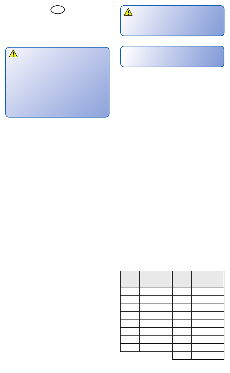
1. Die beiden Kabelenden
werden durch den Lampen-
schirm hindurchgefädelt.
1. Slide the two cable ends
through the lamp shade.
2. Es folgt der Lampenmast;
auch er wird auf die beiden
Kabel aufgeschoben.
2. Also the lamp mast is slid
onto the cables.
3. Danach den Steckfuß auf
die Kabel schieben.
3. Slide the base socket on
the cables.
4. Dann wird der LED-
Leuchtkörper im Lampen-
schirm platziert.
4. Afterwards the LED is
placed in the lamp shade.
5. Schieben Sie das gelbe
Stück Schrumpfschlauch auf
das gelbe Kabel.
5. Slide the yellow part of
the heat shrink tube on the
yellow cable.
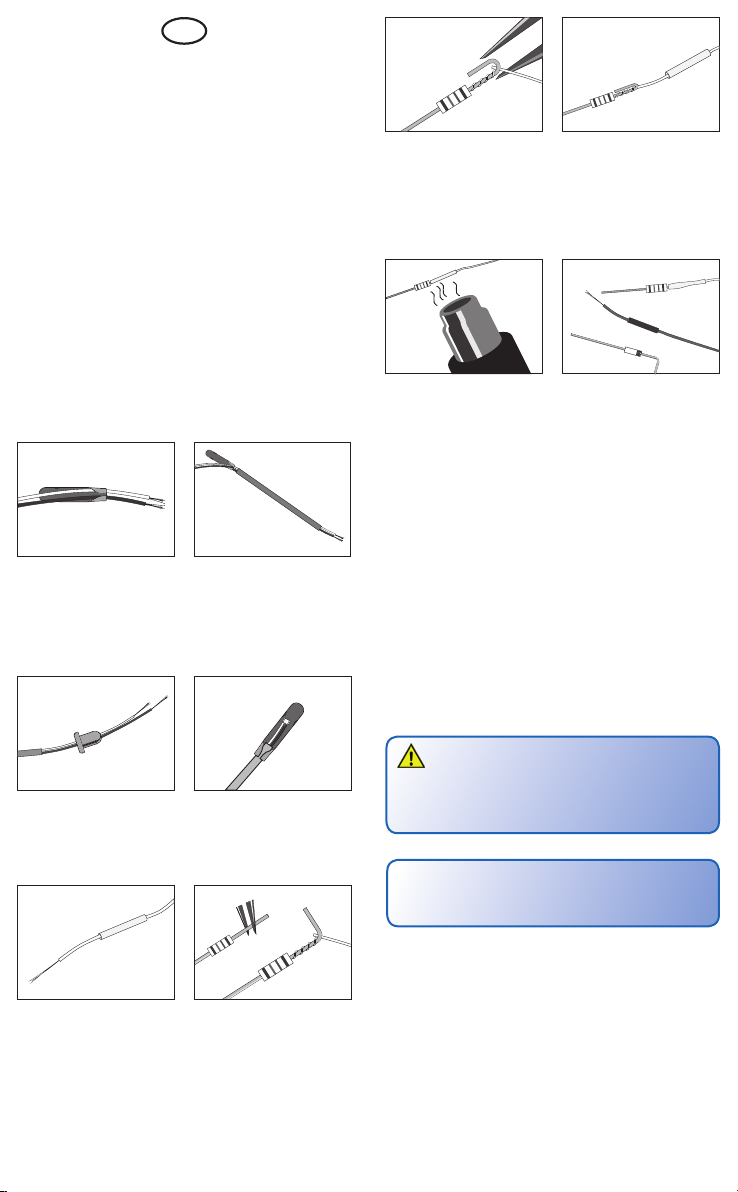
6. Biegen Sie das kurze Ende
des Drahtes in der Mitte um
90 Grad. Wickeln Sie das
blanke Kabelende um das
Drahtstück direkt unterhalb
des beigen Widerstandes.
6. Bend the short end of the
cable in the middle around
90 °. Wind the blank cable
end directly below the beige
resistor.
7. Anschließend biegen Sie
das senkrecht hochstehende
Ende des Widerstandes um.
7. Afterwards bend the verti-
cal end of the resistor.
8. Schieben Sie den
Schrumpfschlauch auf die
zuvor hergestellte Kontakt-
stelle (Kabel + Widerstand).
8. Slide the heat shrink tube
on the contact point which
was made prior to this (cable
+ resistor)...
9. Kurz (!) erhitzen, etwa mit
einem Heißluftpistole oder
einem Feuerzeug. Schon ist
die dauerhafte Verbindung
fertig! Vorsicht Verbren-
nungsgefahr!
9. Heat it briey (!), e. g. with
a hot air gun or a lighter and
a durable connection has
been accomplished!
Attention: Risk of burn!
11. In gleicher Weise verfährt
man mit dem braunen Kabel,
dem schwarzen Schrumpf-
schlauch und der dunklen
Diode.
11. Proceed in the same
manner with the brown cable,
the black heat shrink tube
and the dark diode.
EN
1. Important information!
Please read this manual completely and attentively before
using the product for the rst time. Keep this manual.
It is part of the product.
Safety information
Caution:
Risk of injury!
Due to the detailed reproduction of the original and the
intended use, this product can have peaks, edges and
breakable parts. For installation tools are required.
Electrical hazard!
Never put the connecting wires into a power socket! Regu-
larly examine the transformer for damage. In case of any
damage, do not use the transformer!
Installation and electrical wiring may only be carried out
while the power supply is switched off. Only use transform-
ers compliant with VDE/EN standards.
Using the product for its correct purpose
This product is designed:
- For installation into a model railroad layouts and dioramas.
- For connection to an authorized model railroad
transformer (e. g. item-No. 5200).
- For use in dry rooms only.
Using the product for any other purpose is not approved and
is considered incorrect. The manufacturer is not responsible
for any damage resulting from the improper use of this
product.
Checking the package contents
Check the mechanic components according to the photo on
the packaging and the electrical components according to the
following list.
- base socket
- colour lter (not with all models)
- 2 x heat shrink tube
- 1 x resistor
- 1 x diode
- Manual
2. Introduction
This lamp produces by SMD-LED the light which is suitable
to the lamp model. Low heat build-up and power input. Nearly
unlimited lifetime of the LED, so no more change is required.
3. Assembly
- See page 2 chapter 3. „Zusammenbau/Assembly“.
4. Mounting
- Check function before mounting.
- Drill a hole at the mounting place. Diameter see schedule
on page 5.
- Put the cables from outside through the hole and push
the socket into the hole. If necessary, x the lamp with the
xation ring from inside (optional).
Connecting the cable, please leave approx. 2-3 cm behind the
lamp to create a loop, which enables you to pull the lamp out
of the assembly drilling.
Art.-Nr.
item-No.
Durchmesser (d)
der Bohrung
hole diameter (d)
6620 Ø 3,5 mm
6621 Ø 3,5 mm
6625 Ø 2,5 mm
6626 Ø 3,5 mm
6720 Ø 5,5 mm
6721 Ø 5,5 mm
6722 Ø 5,5 mm
6725 Ø 3,5 mm
Art.-Nr.
item-No.
Durchmesser (d)
der Bohrung
hole diameter (d)
6726 Ø 3,5 mm
6727 Ø 5,5 mm
6728 Ø 3,5 mm
6729 Ø 5,5 mm
6920 Ø 3,5 mm
6921 Ø 3,5 mm
6925 Ø 2,5 mm
6926 Ø 3,5 mm
6927 Ø 5,5 mm
5
4
Caution:
Resistor and diode at the cables are needed for proper
function of the lamp. Never cut them off!
Never cover resistor or diode with insulation material,
because they have to be cooled by surrounding air!
5. Connection
Operating voltage: 10-16V AC ~ (with and without 5215
power module), 14-24V DC =,
13-24V digital signal
Operating current: approx. 10 mA
Connect the LED-lamp to the lighting power output of a model
railroad transformer (e. g. item-No. 5200) or power supply as
shown in g. 5 and/or 6.
DC voltage: Connect the diode (red part with black mark)
with the plus pole of the power supply.
AC voltage: Operation with AC voltage could cause some
ickering. We recommend to use the Viessmann power
module item-No. 5215 (g. 6) which is sufcient for approx.
100 LED-lamps or reectors. Connect the cable to the diode
with the brown output socket (g. 5).
This manual suits for next models
7
Table of contents
Languages:
Other Viessmann Work Light manuals


Popular Work Light manuals by other brands


PowerSmith
PowerSmith PWLD080T Operator's manual

MaxLite
MaxLite 73683 installation instructions

Heitronic
Heitronic Trend 27867 Installation and operating instructions

Monzana
Monzana Gore MZCL10 manual

EINHELL
EINHELL TE-CL 18/2000 LiAC Original operating instructions

Bayco
Bayco NIGHTSTICK Dual-Light Xtreme Lumens... instruction manual