VIEWEG DV-5120 User manual

VIEWEG
DE
Bedienungsanleitung
Schlauchquetschventil DV-5120
© VIEWEG GmbH
Version 2021/09-01
EN
Operating Instructions
Pinch Tube Valve DV-5120

DE
Ihre VIEWEG GmbH
1 Allgemeines
Sehr geehrte Kundin, sehr geehrter Kunde,
vielen Dank, dass Sie sich für dieses Dosierventil entschieden haben.
Um ein einwandfreies Funktionieren zu gewährleisten, lesen Sie bitte diese Bedienungs-
anleitung sorgfältig durch und bewahren Sie sie auf, um auch zukünftig nachschlagen
zu können.
Falls Sie weitere Informationen benötigen oder wenn Fragen auftreten sollten, die in
dieser Bedienungsanleitung für Sie nicht ausführlich genug behandelt werden, dann
wenden Sie sich bitte direkt an uns.
1 Allgemeines . . . . . . . . . . . . . . . . . . . . . . . . . . . . . . . . . . . . . . . . . . . . . . 3
1.1 Das DV-5120 . . . . . . . . . . . . . . . . . . . . . . . . . . . . . . . . . . . . . . . . 4
1.2 Bestimmungsgemäße Verwendung . . . . . . . . . . . . . . . . . . . . . . . . . 4
1.3 Lieferumfang . . . . . . . . . . . . . . . . . . . . . . . . . . . . . . . . . . . . . . . . 5
2 Sicherheitshinweise . . . . . . . . . . . . . . . . . . . . . . . . . . . . . . . . . . . . . . . . . 6
2.1 Allgemeines zur Sicherheit . . . . . . . . . . . . . . . . . . . . . . . . . . . . . . . 6
2.2 Gefahren für den Bediener . . . . . . . . . . . . . . . . . . . . . . . . . . . . . . . 6
2.3 Sicherheitshinweise zu Hilfs- und Betriebsstoffen . . . . . . . . . . . . . . . . . 6
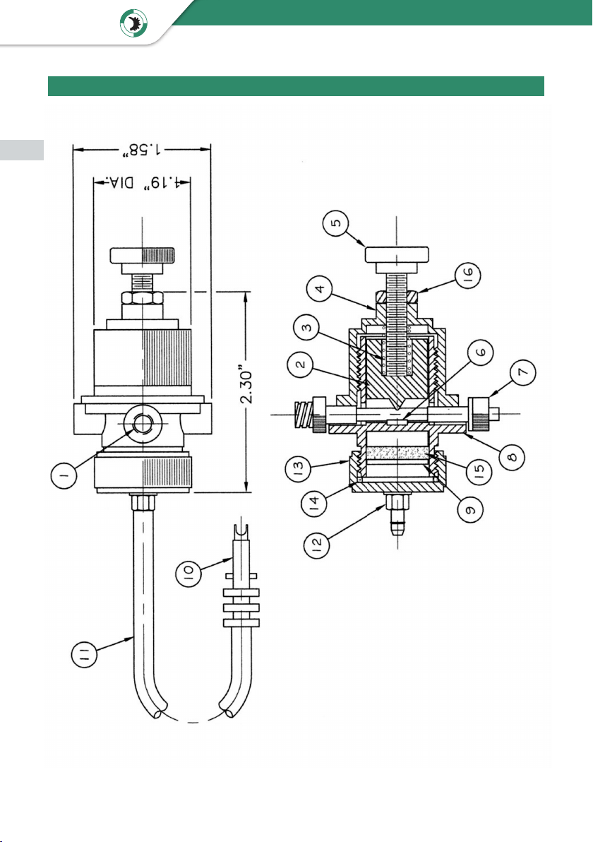
3 Über Ihr Dosierventil . . . . . . . . . . . . . . . . . . . . . . . . . . . . . . . . . . . . . . . . 7
4 Inbetriebnahme . . . . . . . . . . . . . . . . . . . . . . . . . . . . . . . . . . . . . . . . . . . 8
4.1 Einlegen oder wechseln des Schlaucheinsatzes . . . . . . . . . . . . . . . . . . 8
4.2 Anschließen der Materialversorgung . . . . . . . . . . . . . . . . . . . . . . . . . 9
4.3 Anschließen der Steuerluft . . . . . . . . . . . . . . . . . . . . . . . . . . . . . . 10
4.4 Ventil einstellen . . . . . . . . . . . . . . . . . . . . . . . . . . . . . . . . . . . . . 10
5 Ersatzteile . . . . . . . . . . . . . . . . . . . . . . . . . . . . . . . . . . . . . . . . . . . . . . 11
Inhaltsverzeichnis
2 3
Bedienungsanleitung DV-5120
VIEWEG

DE
1.1 Das DV-5120
Mit dem Schlauchquetschventil lassen sich Dosierungen von sehr kleinen Dosier-
punkten bis zur kontinuierlichen Dosierung von Raupen für nieder- bis mittelviskose
Materialien durchführen.
Der auswechselbarer Schlaucheinsatz ist das einzige Teil des Ventils, das Berührung mit
Ihrem Material hat. In diesem kurzen Stück Schlauch erzeugt das Ventil durch Eindrehen
einer Stellschraube eine Engstelle und verringert somit den Durchfluss und somit die
Dosiermenge.
Durch Anlegen einer Steuerluft wird ein Verschlusskolben bewegt, der je nach
Einstellung der Stellschraube den Materialweg freigibt. Geschlossen wird das Ventil per
Federkraft.
1.2 Bestimmungsgemäße Verwendung
Das Gerät ist für den gewerblichen Gebrauch konzipiert und konstruiert. Es dient nur
zum Dosieren von flüssigen Materialen wie Klebstoff, Paste, Fett, Öl, Silikon und ähnli-
chen. Jede andere Verwendung gilt als nicht bestimmungsgemäß. Wird dieses Gerät für
andere Zwecke eingesetzt, kann es zu Personen- oder Sachschäden kommen.
Der Hersteller übernimmt keine Haftung für Folgen aus nicht bestimmungsgemäßer
Verwendung.
Zu nicht bestimmungsgemäßer Verwendung zählen:
• Änderungen am Gerät und seinen Komponenten, die nicht ausdrücklich in der
Bedienungsanleitung empfohlen werden
• Einsatz nicht kompatibler, oder beschädigter Ersatzteile
• Verwendung von nicht zugelassenem Zubehör oder Hilfsgeräten
• Überschreiten der zugelassenen und empfohlenen Drücke
3
Bedienungsanleitung DV-5120
VIEWEG

DE
Bedienungsanleitung
Druckluftschlauch mit Gerätestecker
(Art.-Nr. 501305) (Art.-Nr. 501781)
Dosiernadelsortiment klein
(Art.-Nr. 503338)
Dosierventil DV-5120
(auf diesem Foto mit eingelegtem Schlaucheinsatz)
1.3 Lieferumfang
Im Lieferumfang sind folgende Teile enthalten:
Schlaucheinsatz Innen-Ø 1,8 mm
(Art.-Nr. 501787)
Schlaucheinsatz Innen-Ø 2,5 mm
(Art.-Nr. 501782)
Haltestange für Quetschventil
(Art.-Nr. 501779)
Schlauchklemme
(Art.-Nr. 501875)
4 5
Bedienungsanleitung DV-5120
VIEWEG

DE
2.1 Allgemeines zur Sicherheit
2 Sicherheitshinweise
Wird dieses Ventil für andere Zwecke eingesetzt, als in
dieser Bedienungsanleitung beschrieben, kann es zu
Personen- oder Sachschäden kommen.
Setzen Sie das Ventil nur gemäß der Anleitung ein.
2.2 Gefahren für den Bediener
Vor Gebrauch die Bedienungsanleitung sorgfältig lesen.
Tragen Sie immer die geeignete Schutzkleidung und
Augenschutz.
Rauchen oder offenes Feuer sind bei der Dosierung
brennbarer Medien untersagt.
Dieses Ventil ist nur für den Gebrauch in geschlossenen
Räumen vorgesehen.
2.3 Sicherheitshinweise zu Hilfs- und Betriebsstoffen
Einzelheiten hinsichtlich der ordnungsgemäßen Hand-
habung und Sicherheitsvorkehrungen finden Sie im
Sicherheitsdatenblatt des verwendeten Dosier-
materials.
WARNUNG
VORSICHT
WICHTIG
5
Bedienungsanleitung DV-5120
VIEWEG

DE
3 Über Ihr Dosierventil
1 Druckluftanschluss für Steuerluft
2 Ventilkörper
3 Schlaucheinsatz (wechselbar)
4 Flanschkappe
5 Stellschraube
6 Kontermutter
7 Materiel Einlass
8 Befestigungsmöglichkeit für Haltestange
9Material Auslass
1 3
5
4
76
2
8
9
6 7
Bedienungsanleitung DV-5120
VIEWEG

DE
4 Inbetriebnahme
4.1 Einlegen oder wechseln des Schlaucheinsatzes
Stellen Sie vor der Wartung sicher, dass das System nicht unter Druck steht!
Vergewissern Sie sich, dass keine Flüssigkeit mehr im Ventil ist.
Tragen Sie Schutzhandschuhe und- Brille, bevor Sie das Ventil auseinander nehmen.
Schrauben Sie die Flanschkappe ab. Diese steht unter leichter
Federspannung.
Entfernen Sie die Feder und den Verschlusskolben aus dem
Ventilkörper.
Lösen und entfernen Sie gegebenenfalls den benutzten Schlauch-
einsatz und ziehen diesen mit dem dickeren Luer-Lock-Anschluss
voran durch die Öffnungen aus dem Ventil.
Führen Sie den neuen Schlaucheinsatz mit dem dünnen Luer-
Lock-Anschluss voran ein und drücken ihn dann in die Füh-
rungen.
Biegen Sie den Schlaucheinsatz an den zwei Metallstiften vorbei.
Plazieren Sie den Verschlusskolben so, dass die Metallstifte in die
Bohrungen passen.
Schrauben Sie die Flanschkappe inklusive der Feder wieder auf
das Ventil.
Achten Sie hierbei darauf, daß die Feder die Stellschraube beim
Eindrehen umschließt.
7
Bedienungsanleitung DV-5120
VIEWEG

DE
So ist sichergestellt, daß die Ventileinstellung, wie in Kapitel 4.4
beschrieben, funktioniert.
4.2 Anschließen der Materialversorgung
Materialien mit höherer Viskosität, also zähflüssigere Materialien, benötigen zusätzlich
Druckluft, um zum Ventil zu gelangen.
Versorgen Sie deshalb Ihren Materialbehälter mit Druckluft. Beachten Sie hierbei den
maximal zulässigen Druck.
Entlüften Sie vor dem Verwenden den Materialschlauch
und das Ventil um blasenfrei zu dosieren.
WICHTIG
Achten Sie in diesem Fall darauf, dass sich der
Materialbehälter mindestens 20 cm oberhalb des
Ventils befindet.
WICHTIG
Schließen Sie den Schlauch mit Ihrem Dosiermaterial an den
Materialeingang des Ventils an.
Wenn Ihr Dosiermaterial Material flüssig genug ist (niedrige
Viskosität), um selbständig zufließen, ist es möglich, das Material
ohne zusätzlichen Druck am Ventil anzuschließen.
Am Materialausgang lassen sich zum Beispiel Dosiernadeln oder
Mischrohre anschließen, um das Material punktgenau
aufzutragen.
An der Seite des Ventils befindet sich ein Gewindebohrung.
Hier kann die mitgelieferte Haltestange eingeschraubt werden,
um das Ventil z.B. an einem Stativ zu befestigen. Das Ventil arbei-
tet in jeder Position.
8 9
Bedienungsanleitung DV-5120
VIEWEG

DE
4.4 Ventil einstellen
Mit Hilfe eines Verschlusskolbens wird in dem Ventil eine Engstelle in einem Schlauch-
einsatz erzeugt. Das Öffnen oder Schließen der Stellschraube weitet oder verengt diese
Engstelle und regelt somit die Dosiermenge.
Der Steuerluftanschluss sollte an ein 3/2-Wege-Ventil
oder ein passendes Ventilsteuergerät angeschlossen
werden.
WICHTIG
4.3 Anschließen der Steuerluft
Zu Öffnen des Ventils wird ein minimaler Steuerdruck von 4,5 bar benötigt. Ohne diesen
Druck schließt das Ventil durch die interne Federkraft.
Zum Anschließen der Steuerluft können Sie den mitgelieferten
Druckluftschlauch mit Gerätestecker verwenden.
Schließen Sie diesen am Druckluftanschluss des Ventils an und
sichern diesen mit der mitgelieferten Schlauchklemme.
Lösen Sie die Kontermutter (in Richtung Stellschraube) und
drehen Sie die Stellschraube komplett zu. Somit ist das Ventil
geschlossen.
Öffnen Sie Ihre Druckzufuhr.
Stellen Sie mit der Stellschraube den gewünschten Durchfluss
Ihres Dosiermaterials ein.
Wenn Sie die korrekte Einstellung gefunden haben, drehen Sie die
Kontermutter (in Richtung Ventil) wieder fest.
So dosieren Sie immer in der gleichen Einstellung.
9
Bedienungsanleitung DV-5120
VIEWEG

DE
5 Ersatzteile
10 11
Bedienungsanleitung DV-5120
VIEWEG

DE
Nr. Artikel-Nr. Beschreibung
1 501779 Haltestange
2 501772 Quetschkolben
3 501775 Feder
4 580024NM Flanschkappe
5 580029NM Stellschraube
6 580026NM Gummipad
7 501787 oder 501782 Schlaucheinsatz
8 501770 Ventilkörper
9 501774 Kolben
10 501781 Gerätestecker
11 501305 Druckluftschlauch
12 501875 Schlauchfixierung
13 501771 Zylinderkappe
14 501776 Dichtung
15 501777 Dichtung
16 580036NM 1/4-28 Kontermutter
o. Abb. 501875 Schlauchklemme
11
Bedienungsanleitung DV-5120
VIEWEG

VIEWEG
EN
1 General information
Dear customer,
Thank you for choosing our model DV-5120 dispensing valve.
To ensure proper operation, please carefully read the following pages for correct
operating and maintenance instructions. Keep these instructions handy for future reference.
If you require further information or if you have any questions please contact us directly at
Phone: +49 8166 6784 -0
Email: info@dosieren.de
Contents
1 General information . . . . . . . . . . . . . . . . . . . . . . . . . . . . . . . . . . . . . . . . 12
1.1 The DV-5120 . . . . . . . . . . . . . . . . . . . . . . . . . . . . . . . . . . . . . . . 13
1.2 Intended Use . . . . . . . . . . . . . . . . . . . . . . . . . . . . . . . . . . . . . . . 13
1.3 Scope of delivery . . . . . . . . . . . . . . . . . . . . . . . . . . . . . . . . . . . . 14
2 Safety instructions . . . . . . . . . . . . . . . . . . . . . . . . . . . . . . . . . . . . . . . . . 15
2.1 General safety information . . . . . . . . . . . . . . . . . . . . . . . . . . . . . . 15
2.2 Dangers for the operator . . . . . . . . . . . . . . . . . . . . . . . . . . . . . . . 15
2.3 Safety Instructions for Auxiliary and Operating Materials . . . . . . . . . . . 15
3 About your dispensing valve . . . . . . . . . . . . . . . . . . . . . . . . . . . . . . . . . . 16
4 Commissioning. . . . . . . . . . . . . . . . . . . . . . . . . . . . . . . . . . . . . . . . . . . 17
4.1 Inserting or changing the tube insert . . . . . . . . . . . . . . . . . . . . . . . 17
4.2 Connecting the material supply . . . . . . . . . . . . . . . . . . . . . . . . . . . 18
4.3 Anschließen der Steuerluft . . . . . . . . . . . . . . . . . . . . . . . . . . . . . . 19
4.4 Ventil einstellen . . . . . . . . . . . . . . . . . . . . . . . . . . . . . . . . . . . . . 19
5 Spare Parts . . . . . . . . . . . . . . . . . . . . . . . . . . . . . . . . . . . . . . . . . . . . . . 20
12 13
Operating Instructions DV-5120

VIEWEG
EN
1.1 The DV-5120
The Pinch Tube Valve provides a wide degree of control for continuous or micro shot
applications of low to semi-viscous fluids.
The“ON/OFF”control is achieved by automatically opening and pinching a molded
polyethylene tube assembly. The adjustable degree of opening or releasing the pinch
closing on the tube assembly determines the shot size or flow rate. In addition, the
air-powered valve can be timed to develop desired shot sizes. Finally, a wide range of
needle tips can be used to further refine the amount of the dispensed output.
The only part of the valve making contact with the fluid being dispensed is the
disposable tube assembly.
1.2 Intended Use
The device is designed and constructed for commercial use. It is only to be used for
dispensing liquid and paste materials such as adhesives, lubricants, various pastes, grease,
oil, silicone and other similar materials. Any other use is considered improper. If this device
is used for other purposes, personal injury or damage to property may result.
The manufacturer assumes no responsibility for consequences resulting from improper
use of the unit.
Non-intended use, which would also void the warranty, includes:
• Changes to the device not expressly recommended in the operating instructions
• Modifications to the unit and its components
• Use of incompatible or damaged spare parts
• Use of non-approved accessories or auxiliary equipment
• Exceeding the approved and recommended pressures
13
Operating Instructions DV-5120

VIEWEG
EN operating instructions
compressed air hose with quick connect
(Item no. 501305) (Item no. 501781)
dispensing tip set small
(Item no. 503338)
dispensing valve DV-5120
(on this photo with inserted tube insert)
1.3 Scope of delivery
The following accessories are included with the DV-5120 valve
tube insert inner-Ø 1,8 mm
(Item no. 501787)
tube insert inner-Ø 2,5 mm
(Item no. 501782)
rod mount for pinch tube valve
(Item no. 501779)
hose clamp
(Item no. 501875)
14 15
Operating Instructions DV-5120

VIEWEG
EN
2.3 Safety Instructions for Auxiliary and Operating Materials
For details on proper handling and safety precautions,
for materials to be dispensed ALWAYS check the
Material Safety Data Sheet (MSDS).
WARNING
CAUTION
NOTICE
2.1 General safety information
2 Safety instructions
If this device is used for purposes other than those
described in this operating manual, personal injury or
damage to property may result.
Only use the device in accordance with the enclosed
instructions.
2.2 Dangers for the operator
Read the operating instructions carefully before use.
Always wear suitable protective clothing and eye wear.
Smoking or open flames are strictly prohibited when
dispensing any type of flammable liquid or paste.
This device is intended for indoor use only.
15
Operating Instructions DV-5120

VIEWEG
EN
3 About your dispensing valve
1 compressed air connection for
control air
2 valve body
3 tube insert (replaceable)
4 flange cap
5 adjusting knob
6 locknut
7 material inlet
8 fastening possibility for rod mount
9material outlet
1 3
5
4
76
2
8
9
16 17
Operating Instructions DV-5120

VIEWEG
EN
4 Commissioning
4.1 Inserting or changing the tube insert
Before maintenance, make sure that the system is not under pressure!
Make sure that there is no liquid left in the valve.
Wear protective gloves and goggles before disassembling the valve.
Unscrew the flange cap. This is under slight spring tension.
Remove the spring and the closing piston from the valve body.
If necessary, loosen and remove the used tube insert and pull it
out of the valve through the openings with the thicker Luer lock
connection first.
Insert the new tube insert with the thin Luer lock connector first
and then press it into the guides.
Bend the hose insert past the two metal pins.
Place the sealing plunger so that the metal pins fit into the holes.
Screw the flange cap including the spring back onto the valve.
Make sure that the spring encloses the set screw when screwing
it in.
17
Operating Instructions DV-5120

VIEWEG
NOTICE
NOTICE
EN
This ensures that the valve setting functions as described in
chapter 4.4.
4.2 Connecting the material supply
Materials with higher viscosity, i.e. more viscous materials, require additional com-
pressed air to reach the valve.
Therefore, supply your material container with compressed air. Observe the maximum
permissible pressure.
Before use, vent the material hose and the valve in
order to dispense without bubbles.
In this case, make sure that the material container is at
least 20 cm above the valve.
Connect the hose with your dispensing material to the material
inlet of the valve.
If your dispensing material is fluid enough (low viscosity) to flow
independently, it is possible to connect the material to the valve
without additional pressure.
For example, metering needles or mixing tubes can be connected
to the material outlet to apply the material with pinpoint
accuracy.
There is a threaded hole on the side of the valve.
The supplied holding rod can be screwed in here to attach the
valve to a tripod, for example. The valve works in any position.
18 19
Operating Instructions DV-5120

VIEWEG
NOTICE
EN
4.4 Adjusting the valve
A closing piston is used to create a constriction in a hose insert in the valve. Opening or
closing the adjusting screw widens or narrows this constriction and thus regulates the
dispensing quantity.
The control air connection should be connected to a
3/2-way valve or a suitable valve control unit.
4.3 Connecting the control air
A minimum control pressure of 4.5 bar is required to open the valve.
Without this pressure, the valve closes by the internal spring force.
To connect the control air, you can use the supplied compressed
air hose with quick connect.
Connect this to the compressed air connection of the valve and
secure it with the supplied hose clamp.
Loosen the lock nut (in the direction of the adjusting screw) and
close the adjusting screw completely. This closes the valve.
Open your pressure supply.
Use the adjusting knop to set the desired flow rate of your
dispensing material.
When you have found the correct setting, tighten the lock nut
again (in the direction of the valve).
In this way, you will always dispense at the same setting.
19
Operating Instructions DV-5120

VIEWEG
EN
5 Spare Parts
20 21
Operating Instructions DV-5120
Table of contents
Languages:
Other VIEWEG Control Unit manuals
Popular Control Unit manuals by other brands

SmartOne
SmartOne 70-600000-001 installation instructions

Tektronix
Tektronix L3 instruction manual

Hansen
Hansen H5600A Specifications, Applications, Service Instructions & Parts

Emerson
Emerson BM6X Series instruction manual

Huawei
Huawei PDU5000 quick guide

Intertec Data Systems
Intertec Data Systems MPR-A Series instruction sheet

Metso
Metso 530S Installation maintenance and operating instructions

Kohler
Kohler BEAM K-77691K-G installation instructions

Acqiris
Acqiris SA230E Startup guide

FATEK
FATEK FBs-CM25 user manual

Alutech
Alutech CUID-400N Assembly and operation manual

National Instruments
National Instruments SCXI-1502 user manual