manuals.online logo
Brands
  1. Home
  2. •
  3. Brands
  4. •
  5. Vimar
  6. •
  7. Intercom System
  8. •
  9. Vimar ELVOX 6570 Assembly instructions

Vimar ELVOX 6570 Assembly instructions

Manuale installatore - Installer guide
Manuel installateur - Technisches Handbuch
Instrucciones instalador - Manual do instalador
6570 - 657C
Unità Due Fili video in b/n - Unità Due Fili video a colori
Due Fili b/w video electronic unit - Due Fili colour video unit
Unité électron. Due Fili vidéo b/n - Unité Due Fili vidéo couleurs
S/W Video-Elektronikeinheit DueFili- DueFili Farb-Videoeinheit
Unidad electrónica Due Fili vídeo b/n - Unidad Due Fili vídeo en color
Unidade electrónica Due Fili vídeo b/p - Unidade electrónica Due Fili vídeo a cores
2
ENFRDEESPT IT
8000
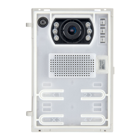
Questo tipo di unità di ripresa CCD può essere
montato solo su targhe serie 8000 e su targhe
con buca posta Art. 2550/301-302. L’art. 6570 di-
spone di telecamera in B/N mentre l’art. 657C di
telecamera a colori.
Questi articoli vanno utilizzati assieme all’Art.
6931 .
Caratteristiche
- Sensore CCD 1/4” standard CCIR per 6570 e
Standard PAL per 657C
- Obiettivo autoiride 3,0 mm fuoco fisso
- Temperatura di funzionamento -5° +50° C
- Alimentazione da BUS Due Fili (28Vcc)
- Livello di illuminazione al soggetto minimo 0,5
lux
- Illuminatore a infrarosso per Art. 6570 e bianco
per Art. 657C
Particolare attenzione si deve porre ai collega-
menti; collegare la linea BUS ai morsetti 1 e 2
e collegare i morsetti + e - al posto esterno Art.
6931 (+ = Rosso, - = Nero).
Per quanto riguarda la programmazione si deve
fare riferimento all’istruzione dell’articolo 6931.
This CCD camera is mounted only on entrance
panels series 8000 and on entrance panels with
letter box Art. 2550/301-302.
Type 6570 is equipped with a B/W camera, while
type 657C is equipped with a colour camera.
These articles are to be used in conjunction with
Art. 6931.
Characteristics
- ¼’’ CCD Sensor Standard CCIR for 6570 and
Standard PAL for 657C
- 3.0mm auto-iris lens with non-adjustable focus
- Operating temperature -5° +50°C
- Supply voltage from “Bus two wires” (28V
D.C.)
- Minimum lighting level 0,5 lux
- Infrared Led for Art. 6570 and white for Art.
657C
Pay attention to the connections; connect the bus
line to terminals 1 and 2 and connect terminals
+ and – to speech unit type 6931 (+ = Red, - =
Black).
For the programming see instructions concerning
Art. 6931.
Caméra à monter uniquement dans les plaques
de rue série 8000 et dans plaques de rue avec
boîte aux lettres Art. 2550/301-302.
L’Art. 6570 dispose d’une caméra en B/N, tandis
que l’Art. 657C dispose d’une caméra en cou-
leurs.
Ces articles sont utilisés avec l’Art. 6931.
Caractéristiques
- Senseur CCD ¼’’ Standard CCIR pour 6570 et
Standard PAL pour 657C
- Objectif à diaphragme automatique 3,0mm
focus fixe
- Température de fonctionnement -5° + 50° C
- Alimentation depuis Bus deux fils (28V c.c.)
- Niveau d’éclairage minimum 0,5 lux.
- Led infrarouge pour Art. 6570 et blanche pour
Art. 657C
Attention particulière on doit faire aux raccorde-
ments: raccorder la ligne BUS aux bornes 1 et 2
et raccorder les bornes + et – au poste externe
Art. 6931 (+ = Rouge, - = Noir).
Pour la programmation voir les instructions de
l’Art. 6931.
Diese CCD-KAMERAEINHEITEN nur in Klingel-
tableaus der Serie 8000 montiert werden und an
Klingeltableaus mit Briefkasten Art. 2550/301-
302. Art. 6570 verfügt über eine S/W Kamera,
während Art. 657C verfügt über eine Farbkamera.
Diese Artikel werden zusammen mit Art. 6931 be-
nutzt.
Eigenschaften
- ¼’’ CCD Sensor Standard CCIR für 6570 und
Standard PAL für 657C
- Objektiv mit Automatik Blende 3,0mm Fokus
fest eingestellt
- Betriebstemperatur von -5° + 50°C
- Versorgungsspannung aus BUS zwei Drähten
(28V= GLEICHSTROM)
- Mindestbeleuchtung 0,5 lux
- Infrarot-Led für Art. 6570 und weiss für Art.
657C
Besondere Achtung für die Anschlüsse: die
BUS-Leitung an Klemmen 1 und 2 und die Klem-
men + und – an die Aussenstelle Art. 6931 an-
schliessen (+ = Rot, - = Schwarz).
Für die Programmierung siehe Leitungen des Art.
6931.
Este tipo de cámara CCD se monta solamente en
las placas serie 8000 y en las placas con buzón
Art. 2550/301-302. El Art. 6570 dispone de cá-
mara en B/N, mientras el Art. 657C dispone de
cámara en color. Estos artículos se utilizan junto
con el Art. 6931.
Carácteristicas
- Sensor CCD ¼’’ Estándar CCIR para 6570 y
Estándar PAL para 657C
- Objetivo autoiris 3,0mm con focal fijo
- Temperatura de funcionamiento - 5° + 50° C
- Alimentación desde BUS Dos Hilos (28V c.c.)
- Nivel mínimo de iluminación del sujeto: 0,3 lux
- Led al infrarojo para Art. 6570 y blanco para
Art. 657C
Particular atención hay que prestar a las
conexiones; conectar la línea BUS a los bornes 1
y 2 y conectar los bornes + y – al aparato externo
Art. 6931 (+ = Rojo, - = Negro).
Para la alimentación ver las instrucciones del Art.
6931 .
Este tipo de têlecâmara CCD tem de ser montado
só em botoneiras série 8000 e nas caixas de cor-
reio Art. 2550/301-302.
O Art. 6570 dispõe de telecâmara em B/P, en-
quanto o Art. 657C dispõe de telecâmara a cores.
Estes artículos utizam-se com o Art. 6931.
Características
- Sensor CCD ¼’’ Estándar CCIR para 6570 e
Estándar PAL para 657C
- Objectiva auto-íris 3,0mm foco fixo.
- Temperatura de funcionamento: -5°C +50°C
- Alimentação desde o BUS Dois Fios (28V c.c.).
- Nível mínimo de iluminação do sujeito 0,3 lux
- Led de infravermelhos para Art. 6570 e branco
para Art. 657C
Ter em particular atenção às ligações: ligar a
linha BUS aos terminais 1 e 2 e ligar os terminas
+ e – ao posto externo Art. 6931 (+ = ermelho,
- = Preto).
Para a alimentação ver as instruções do Art.
6931.
Fig.1
A- LED Infrarosso o bianco
Infrared LED or white
LED à infrarouge ou blanche
Infrarot-LED oder weiss
LED al infrarojo o blanco
LED de infravermelhos ou branco TELECAMERA
CAMERA
CAMÉRA
KAMERA
CÁMARA
TELECÂMARA
PT
ES
DE
FR
ENIT
É possível descarregar o manual de
instruções no site www.vimar.com
El manual de instrucciones se puede
descargar en la página web www.vi-
mar.com
Die Bedienungsanleitung ist auf der
Website www.vimar.com zum Down-
load verfügbar
Il manuale istruzioni è scaricabile dal
sito www.vimar.com
The instruction manual is downloadable
from the site www.vimar.com
Télécharger le manuel d’instructions
sur le site www.vimar.com
3
PTESDEFRENIT
8000
Fissaggio di sicurezza sul retro dell’unità di ripresa e contemporaneo fissaggio
dei particolari “A” per la serratura a vite e “B” per il posizionamento del posto
esterno.
N.B. Il supporto accessorio (B) in dotazione alla telecamera viene utilizzato per
il montaggio del posto esterno quando si utilizzano i moduli Art. 8020 e 8C20
nelle targhe serie 8000; non viene utilizzato invece quando la telecamera viene
utilizzata in targhe con buca per posta.
Rear fixing of the camera unit and fixing of parts “A” is done using screw attach-
ment and “B” for the speech unit mounting.
Note: The support accessory (B) supplied with the speech unit is used when
modules 8020 and 8C20 are installed with the 8000 series entry panels. The
accessory is not required when the camera is used with letter-box type entry
panels.
Fixation de sécurité à l’arrière de l’unité de prise de vue et parallèlement fixation
de les pièces “A” pour la serrure à vis et “B” pour le montage du poste externe.
NOTE: le support accessoire (B) livré en standard avec le poste externe est uti-
lisé pour le montage du poste externe lorsqu’on emploie les modules Art. 8020
et 8C20 dans les plaques de la série 8000; par contre il n’est pas utilisé lorsque
la caméra est placée dans plaques avec boîte aux lettres.
Rückseitige Befestigung der Kameraeinheit und Befestigung von Teilen “A” mit-
tels Schraubenmontage und “B” fuer die Außenstellenmontage.
HINWEIS: Die Halterung (B), die als Zubehör mit der Außenstelle mitgelifert
wird, wird für die Montage der Außenstation verwendet, wenn die Module Art.
Nr. 8020 und 8C20 an Außenstationen der Serie 8000 zum Einsatz kommen.
Sie wird hingegen nicht verwendet, wenn die kamera an Außenstationen mit
Briefkasten montiert wird.
Fijación de seguridad detrás de la cámara y fijación simultánea del particulares
“A” para la cerradura a vid y “B” para el montaje del aparato externo.
N.B. El soporte accesorio (B) en dotación al aparato externo viene utilizado para
el montaje del aparato externo cuando se utilizan los Módulos Art. 8020 y 8C20
en las placas multi-system serie 8000; no se puede utilizar en placas con buzón.
Fixação de segurança na parte de trás da telecâmara e simultânea fixação do
pormenores “A” para o aperto por parafuso e “B” para a montagem do posto
esterno.
N.B. O sporte (acessório) (B) fornecido com o posto externo é utilizado para a
montagem do posto externo quando se utilizam os módulos Arts. 8020 e 8C20
nas botoneiras série 8000; não é utilizado, porém, quando a telecâmara é utili-
zada nas botoneiras com caixa de correio.
Fig.3
Fig.4 Installare la telecamera nel lato
destro della buca posta e il posto
esterno nel lato sinistro.
Install the camera on the right hand
side of the mail box and the speech
unit on the left hand side.
Installer la caméra dans le côté
droite de la plaque et le poste ex-
terne dans le côté gauche.
Die Kamera auf der rechten Seite
des Klingeltableaus und die Sprech-
stelle auf der linken Seite einbauen.
Instalar la cámara en el lado dere-
cho del buzón y el aparato externo
en el lado izquierdo.
Instalar a telecâmara no lado direito
da botoneira e o posto externo no
lado ezquerdo.
A
B
La Fig. 5 répresente le champ de prise de vue de la caméra qui devrait être
montée à une hauteur entre 1,40m et 1,70 par rapport au sol.
Les unités de prise de vue (Art. 6570, 657C) peuvent être réglées manuellement
sur l’axe vertical pour un meilleur angle de prise de vue.
Fig. 5 stellt das Ausleuchtzone der Kamera dar, die sollte auf die empfolene
Höhe zwischen 1,40 und 1,70 vom Boden befestigen werden.
Bei den Kameraeinheiten Art. 6570, 657C kann der vertikale Erfassungswinkel
manuell eingestellt werden.
La Fig. 5 representa el campo de captación de la camera, que tendría que ser
montada a una altura aconsejada comperendida entre m. 1,40 y m. 1,70 desde
el nivel de suelo.
Las cámaras Art. 6570, 657C pueden ser reguladas manualmente sobre el eje
vertical para mejorar el ángulo de captación.
A Fig. 5 representa o campo de focagem da telecamara que aconselha-se ficar
a uma altura do pavimento entre 1,40 e 1,70m.
A telecâmara Art. 6570, 657C pode ser regulada manualmente sob o eixo verti-
cal para um melhor ângulo de focagem.
Fig. 5
Fig. 6
Inserimento dell’unità di ri-
presa e del posto esterno.
Insertion of camera and
speech unit.
Insertion de la caméra et
du poste externe.
Kamera und Außenstelle
einsetzen.
Inserción de la cámara y
del aparato externo.
Aplicação da telecâmara e
do posto esterno.
A
Art.6570
Art.657C
Art.6931
Art. 8083+8C20+8010+8054
Fig.2
B
Nella Fig. 5 è rappresentato il
campo di ripresa della telecamera
posizionandola ad un altezza consi-
gliata tra m. 1,40 e m. 1,70 da livello
terra.
Le unità di ripresa Art. 6570, 657C
possono essere regolate manual-
mente sull’asse verticale per un mi-
glior angolo di ripresa.
Fig. 5 shows the coverage of the
camera, which should be mounted
at the raccomanded height from
ground level (between 1.40 and
1.70 m.).
Camera units Art. 6570, 657C can
be adjusted manually on the vertical
axis to improve the coverage angle.
4
ENFRDEESPT IT
8000
PRI
B2B12
1
12
6P
T3
VIDEO
B
C
+
-
T4
A
1
2
T1
6S
5
T2 4
12
1
E+
FP
E-
2
M
CH
+12
M
V3
A
C
B
4
12
2
3
1
13
B
A
C
B2
S+
S-
B1
M
CA
C3.5
-
1
2
+
CBA
C3.9
C3.7
M
VL
C
B
A
C3.9
C3.8
C3
C3.2
C3.1
C3.4
C3.3
C3.5
C3.6
C3.0
ART. 6931
C
A
B
+12
CH
M
2
E-
FP
E+
1
+I+U-
PRI
NOTE:
Quando il posto esterno Art. 6931 presenta più di 4 moduli
supplementari Art. 8054, togliere il ponticello C3.7 e collegare
un alimentatore supplementare Art. 6582 ai morsetti (VL)+ e
(M)-.
NOTE:
When the speech unit Art. 6931 has more than 4
supplementary modules Art. 8054, remove the jumper C3.7
and connect a supplementary power supply to the terminals
(VL)+ and (M)-.
IMPIANTO VIDEOCITOFONICO MONO E PLURIFAMILIARE CON
VIDEOCITOFONI SERIE PETRARCA, GIOTTO, 6600 ED UNA TARGA
VIDEO (RIF. SI527)
VIDEO INTERPHONE ENTRANCE PANEL SYSTEM FOR SINGLE OR
MULTI RESIDENCE WITH MONITORS TYPE PETRARCA, GIOTTO, 6600
AND A VIDEO ENTRANCE PANEL (RIF. SI527).
INSTALLATION DE PORTIER VIDÉO MONO OU MULTIFAMILIAL AVEC
MONITEURS SÉRIE PETRARCA, GIOTTO, 6600 ET UNE PLAQUE DE
RUE VIDÉO (RIF. SI527).
VIDEO-TÜRSPRECHANLAGE FÜR EIN- ODER MEHRFAMILIENHAUS
MIT MONITOREN DER BAUREIHE PETRARCA, GIOTTO, 6600 UND
EINEM VIDEOKLINGELTABLEAU (RIF. SI527).
INSTALACIÓN DE VIDEOPORTERO MONO Y MULTIFAMILIAR CON
MONITORES DE LA SERIE PETRARCA, GIOTTO, 6600 Y UNA PLACA
VÍDEO (RIF. SI527).
INSTALAÇÃO DE VIDEOPORTEIRO MONO E MULTIFAMILIAR
CON MONITORES DA SÉRIE PETRARCA, GIOTTO, 6600, E UMA
BOTONEIRA VIDEO (RIF. SI527).
HINWEIS:
Wenn die Türsprechstelle Art. 6931 mehr als 4 Zusatzmodule
Art. 8054 enthält, die Brücke C3.7 entfernen und ein
zusätzliches Netzteil an den Klemmen (VL)+ und (M)-
anschließen.
NOTES :
lorsque le poste externe Art. 6931 a plus de 4 modules
supplémentaires Art. 8054, enlever le pontet C3.7 et relier
une alimentation supplémentaire aux bornes (VL)+ et (M)-.
NOTAS:
cuando el aparato externo art. 6931 presenta más de cuatro
módulos suplementarios art. 8054, quitar el puente C3.7 y
conectar un alimentador suplementario a los bornes (VL)+ y
(M)-.
MONITOR
Art. 6329
Art. 6329/C
Art. 6349,
Art. 6359
F- Art. 6922.1
Rete
Mains
Réseau
Netz
Red
Rede
MONITOR
Art. 6029+6209+6145
Art. 6029/C+6209+6145
MONITOR
Art. 6621
Art. 662C
Art. 6721
Art. 6611
Art. 661C
Art. 6711
Art. 7211
X
X
X
X
X
X
L
X
NOTAS:
Quando a arte ao ar livre 6931 apresenta mais de quatro
módulos adicionais de Arte 8054, remova o jumper e ligar
uma fonte de alimentação adicional C3.7 Arte 6582 terminais
(VL) + e (M) -.
P
Rete
Mains
Réseau
Netz
Red
Rede
K
K
K
K
MONITOR
Art. 7311, 7321
G- Art. 6923
PRI
B2B12
1
12
6P
T3
VIDEO
B
C
+
-
T4
A
1
2
T1
6S
5
T2 4
12
1
E+
FP
E-
2
M
CH
+12
M
V3
A
C
B
4
12
2
3
1
13
B
A
C
B2
S+
S-
B1
M
CA
C3.5
-
1
2
+
CBA
C3.9
C3.7
M
VL
C
B
A
C3.9
C3.8
C3
C3.2
C3.1
C3.4
C3.3
C3.5
C3.6
C3.0
ART. 6931
C
A
B
+12
CH
M
2
E-
FP
E+
1
+I+U-
PRI
5
PTESDEFRENIT
8000
C3 C3.0
PRI
Art. 732H
B2B12
1
P
B2
S+
S-
B1
M
CA
L
C3.6
C3.4
CH1
CH2
C3.2
C3.5
-
1
2
+
CBA
C3.7
M
VL
CABLE RISER
MONTANTE
1 2
Art. 732H
C3.5
C3.6
C3.2
C3.4
C
B
A
*
*
C3 - Targa audio serie 8000, 2550/301-302
C3.0- Posto esterno audio art. 6931
C3.2- Pulsante di chiamata (CH2)
C3.4- Pulsante di chiamata (CH1)
C3.5- Telecamera art. 6570, 657C
C3.6- Illuminazione cartellino portanome R260
C3.7- Alimentazione LED
C3.8- Modulo supplementare serie 8051, 8052, 8053, 8054
L- Serratura elettrica 12V~ 1A
F- Alimentatore art. 6922.1
G- Alimentatore art. 6923
K- Pulsante per chiamata fuoriporta
P- Comando apriporta
X - Cavo Art. 732H, 732I (Due Fili Twistati)
C3 - Audio entrance panel series 8000, 2550/301-302
C3.0 - Speech unit type 6931
C3.2 - Call push-button (CH2)
C3.4 - Call push-button (CH1)
C3.5- Camera art. 6570, 657C
C3.6 - Name-tag lighting R260
C3.7- Power supply LED
C3.8- Supplementary module 8051, 8052, 8053, 8054
L- 12V D.C. electric lock
F- Power supply art. 6922.1
G- Power supply art. 6923
K- Push-button for outdoor call
P- Lock release control
X- Cable 732H, 732I (Twisted Pair)
C3 - Plaque de rue audio série 8000, 2550/301-302
C3.0 - Poste externe audio art- 6931
C3.2 - Bouton-poussoir d’appel (CH2)
C3.4 - Bouton-poussoir d’appel (CH1)
C3.5- Caméra art. 6570, 657C
C3.6 - Éclairage étiquette porte-noms
C3.7- Alimentation LED
C3.8- Module supplementaire
L- Gâche électrique 12V ~
F- Alimentation art. 6922.1
G- Alimentation art. 6923
K - Poussoir pour appel porte palière
P- Commande ouvre porte
X- Câble Art. 732H, 732I (Deux Fils Torsadés)
C3 - Klingeltableau baureihe 8000, 2550/301-302
C3.0- Türsprechstelle art. 6931
C3.2- Ruftaste (CH2)
C3.4- Ruftaste (CH1)
C3.5- Kamera art. 6570, 657C
C3.6- Namenschildbeleuchtung
C3.7- Versorgung LED
C3.8- Zusatzmodul baureihe 8051, 8052, 8053, 8054
F- Netzgerät art. 6922.1
G- Netzgerät art. 6923
L- Elektrisches Türschloss 12V ~
K - Wohntürruftaste
P- Türöffnungssteuerung
X- Kabel Art. 732H, 732I (Zwei verdrillte Drähte)
C3 - Placa audio serie 8000, 2550/301-302
C3.0 - Aparato externo audio art. 6931
C3.2 - Pulsador de llamada (CH2)
C3.4 - Pulsador de llamada (CH1)
C3.5- Cámara art. 6570, 657C
C3.6 - Iluminación tarjeta portanombres
C3.7- Alimentación del LED
C3.8- Módulo suplementario de la serie 8051, 8052, 8053, 8054
L- Cerradura eléctrica 12V ~ 1A
F- Alimentador art. 6922.1
G- Alimentador art. 6923
K- Pulsador llamada puerta apartamiento
P- Mando abrepuerta
X - Cable Art. 732H, 732I (Dos hilos trenzados)
C3 - Botoneira audio série 8000, 2550/301-302
C3.0- Posto externo audio art. 6931
C3.2- Botão de chamada (CH1)
C3.4- Botão de chamada (CH2)
C3.5- Telecãmara art. 6570, 657C
C3.6- Iluminação do cartão porta-nomes
C3.7- Alimentação do LED
C3.8- Módulo suplementar art. 8051, 8052, 8053, 8054, 12TS
L- Trinco eléctrico 12V ~ 1A
F- Alimentador art. 6922.1
G- Alimentador art. 6923
K- Botão para chamada no patamar
P- Comando abreporta
X - Cabo Art. 732H, 732I (Due Fili Entrançados)
RIF. SI528
VARIANTE DI COLLEGAMENTO PER INSTALLAZIONE TELECAMERA
ART. 6570, 657C E POSTO ESTERNO AUDIO ART. 6931 CON UNO O
DUE PULSANTI DI CHIAMATA.
VARIATION FOR INSTALLATION OF CAMERA TYPE 6570, 657C AND
SPEECH UNIT TYPE 6931 WITH ONE OR TWO CALL PUSH-BUTTONS.
VARIANTE DE RACCORDEMENT POUR INSTALLATION CAMÉRA
ART. 6570, 657C ET POSTE EXTERNE AUDIO ART. 6931 AVEC UN OU
DEUX BOUTONS-POUSSOIRS D’APPEL.
SONDERSCHALTUNG FÜR KAMERA ART. 6570, 657C UND AUDIO-
AUSSENSTELLE ART. 6931 MIT EINER ODER ZWEI RUFTASTEN.
VARIACIÓN DE CONEXIONADO PARA INSTALACIÓN CÁMARA ART.
6570, 657C Y APARATO EXTERNO AUDIO ART. 6931 CON UN O DOS
PULSADORES DE LLAMADA.
VARIANTE DE LIGAÇÃO PARA INSTALAÇÃO TELECÂMARA ART.
6570, 657C E POSTO EXTERNO AUDIO ART. 6931 COM UM OU DOIS
BOTÕES DE CHAMADA.
ALIMENTATORE
POWER SUPPLY
ALIMENTATON
NETZGERÄT
ALIMENTADOR
Rete-Mains
Réseau-Netz
Red-Rede
Art. 6922.1
X
X
Legenda per schemi di collegamento
Legenda for wiring diagram
Légende pour schémas de raccordement
Beschriftung für Schalpläne
Leyenda para esquemas de conexionado
Legenda para esquemas de conexionado
6
ENFRDEESPT IT
8000
** *
** *
TERMINAÇÃO BUS
Esta nota aplica-se a todos os dispositivos da tecnolo-
gia Due Fili Plus dotados do “conector ou dip-switch
de terminação BUS” identificado pela marca serigráfica
“ABC” e assinalado nos esquemas de ligação com *.
Para a adaptação correcta da linha deve fazer-se a
configuração de acordo com a seguinte regra:
Mantenha a posição “A” se o BUS entrar e sair do dis-
positivo;
Desloque-se para a posição “B” (se for um cabo Elvox)
ou para a posição “C” (se for um cabo “CAT5” com
os pares entrançados acoplados), se a linha do BUS
“terminar” no próprio dispositivo.
“A” = NENHUMA TERMINAÇÃO
“B” = TERMINAÇÃO 100 ohm
“C” = TERMINAÇÃO 50 ohm
INSTALAÇÕES COM DISTRIBUIDOR PASSIVO
692D
(versão com “calha DIN”)
Utilize SEMPRE a saída 1 do distribuidor art. 692D
(a única que não tem a ponte de terminação). Para
a terminação do art. 692D: Se as saídas “OUT”, “2”,
“3” ou “4” não forem utilizadas, MANTENHA a ponte
no conector “TOUT”, “T2”, “T3” ou “T4”. Por defeito,
a ponte “TOUT” está na posição “100” (cabo Elvox),
coloque-o em “50” apenas se utilizar um cabo CAT5
com os pares de fios entrelaçados acoplados.
INSTALAÇÕES COM DISTRIBUIDOR ACTIVO
692D/2.
A ponte de terminação deve ser posicionada em “B”
(para o cabo Elvox) ou em “C” (para o cabo CAT5 com
pares de fios entrelaçados acoplados) SE E APENAS
SE o BUS terminar no próprio dispositivo. Deve ser
deixado em “A” se se fizer o “entra/sai” utilizando os
bornes 1-2 do 692D/2.
TERMINACIÓN DEL BUS
Esta nota se aplica a todos los dispositivos con tec-
nología Due Fili Plus provistos de “conector o conmu-
tador DIP de terminación BUS” identificado por la
serigrafía “ABC” y marcado en los esquemas de con-
exión con *.
Para la correcta adaptación de la línea hay que realizar
la configuración según la regla siguiente:
Mantener la posición “A” si el BUS entra y sale del dis-
positivo;
Desplazar a la posición “B” (si el cable es Elvox) o bien
a la posición “C” (si el cable es “CAT5” con los pares
acoplados), si la línea del BUS “termina” en el propio
dispositivo.
“A” = Ninguna TERMINACIÓN
“B” = TERMINACIÓN 100 ohmios
“C” = TERMINACIÓN 50 ohmios
EQUIPOS CON DISTRIBUIDOR PASIVO 692D
(versión con “riel DIN”)
Utilice SIEMPRE la salida 1 del distribuidor Art. 692D
(la única que no tiene el conector puente de termi-
nación).
Para la terminación del Art. 692D: Si no se utilizan las
salidas “OUT”, “2”, “3” o “4”, mantenga el conector pu-
ente en el conector “TOUT”, “T2”, “T3” o “T4” . Por
defecto, el conector puente “TOUT” está en posición
“100” (cable Elvox): colóquelo en “50” solo si se utiliza
un cable CAT5 con los pares acoplados.
EQUIPOS CON DISTRIBUIDOR ACTIVO 692D/2.
El conector puente de terminación debe posicionarse
en “B” (para el cable Elvox) o en “C” (para el cable
CAT5 con pares acoplados) EXCLUSIVAMENTE SI el
BUS termina en el dispositivo. Debe dejarse en “A” si
se utilizan los bornes 1-2 del 692D/2 para entrada-sal-
ida.
TERMINAZIONE BUS
Questa nota si applica a tutti i dispositivi della tecnolo-
gia Due Fili Plus dotati del “connettore o dip-switch di
terminazione BUS” identificato dalla scritta serigrafica
“ABC” e segnalato sugli schemi di collegamento con *
.
Per il corretto adattamento della linea va effettuato il
settaggio secondo la seguente regola:
Mantenere posizione “A” se il BUS entra ed esce dal
dispositivo;
Spostare in posizione “B” (se cavo Elvox) oppure in po-
sizione “C” (se cavo “CAT5” con i doppini accoppiati),
se la linea del BUS “termina” nel dispositivo stesso.
“A” = NESSUNA TERMINAZIONE
“B” = TERMINAZIONE 100 ohm
“C” = TERMINAZIONE 50 ohm
IMPIANTI CON DISTRIBUTORE PASSIVO 692D
(versione “barra din”)
Utilizzare SEMPRE l’uscita 1 del distributore art.692D
(l’unica che non ha il ponticello di terminazione). Per la
terminazione dell’art.692D:
Se le uscite “OUT”, “2”, “3” o “4” non vengono utilizzate,
MANTENERE il ponticello sul connettore “TOUT”, “T2”,
“T3” o “T4” . Il ponticello “TOUT” di default è in posi-
zione “100” (cavo Elvox), posizionarlo su “50” solo se si
utilizza un cavo CAT5 con i doppini accoppiati.
IMPIANTI CON DISTRIBUTORE ATTIVO 692D/2.
Il ponticello di terminazione va posizionato su “B” (per
cavo Elvox) o su “C” (per cavo CAT5 con doppini ac-
coppiati) SE E SOLO SE il BUS termina sul dispositivo
stesso. Va lasciato su “A” se si effettua l’entra-esci uti-
lizzando i morsetti 1-2 del 692D/2.
BUS TERMINATION
This note applies to all devices with Due Fili Plus tech-
nology equipped with “BUS termination connector or
dip-switch”, which is identified by the screen-printed
letters “ABC” and marked on the wiring diagrams with
*.
For correct adaptation of the line, make the setting ac-
cording to the following rule:
Maintain position “A” if the BUS enters and exits from
the device;
Move to position “B” (if Elvox cable) or to position “C”
(if CAT5 twisted pair cable) if the BUS line terminates
in the device itself.
“A” = NO TERMINATION
“B” = TERMINATION 100 ohm
“C” = TERMINATION 50 ohm
INSTALLATIONS WITH PASSIVE DISTRIBUTOR
692D
(DIN rail version)
ALWAYS use output 1 on distributor type 692D (the
only one that has no termination jumper).
For termination of type 692D: If outputs “OUT”, “2”, “3”
or “4” are not used, KEEP the jumper on the “TOUT”,
“T2”, “T3” or “T4” connector. The default “TOUT” con-
nector is in the “100” position (Elvox cable), position it to
“50” only if using a CAT5 twisted pair cable.
INSTALLATIONS WITH ACTIVE DISTRIBUTOR
692D/2.
The termination jumper must be positioned on “B” (for
Elvox cable) or on “C” (for CAT5 twisted pair cable) IF
AND ONLY IF the BUS terminates at the device itself. It
must be left on “A” if effecting entry-exit using terminals
1-2 on 692D/2.
TERMINAISON BUS
Cette remarque concerne tous les dispositifs de la
technologie Due Fili Plus dotés du « connecteur ou du
commutateur de terminaison du Bus » identifié par «
ABC » et indiqué sur les schémas par un *.
Pour l’adaptation correcte de la ligne, procéder au
réglage selon la règle ci-après :
Conserver la position « A » si le Bus entre et sort du
dispositif ;
Déplacer sur la position « B » (câble Elvox) ou sur la
position « C » (câble « CAT5 » à paires torsadées), si
la ligne du Bus « arrive » au dispositif.
“A” = AUCUNE TERMINAISON
“B” = TERMINAISON 100 ohm
“C” = TERMINAISON 50 ohm
INSTALLATIONS AVEC DISTRIBUTEUR PASSIF
692D
(version “rail DIN”)
Utiliser TOUJOURS la sortie 1 du distributeur art. 692D
(la seule qui n’a pas le pontet de terminaison).
Pour la terminaison de l’art. 692D : si toutes les sorties
“OUT”, “2”, “3” ou “4” ne sont pas utilisées, MAINTENIR
le pontet sur le connecteur “TOUT”, “T2”, “T3” ou “T4”.
Le pontet “TOUT” par défaut est en position “100”
(câble Elvox), le positionner sur “50” uniquement si l’on
utilise un câble CAT5 à paires torsadées.
INSTALLATIONS AVEC DISTRIBUTEUR ACTIF
692D/2.
Le pontet de terminaison doit être positionné sur “B”
(pour câble Elvox) ou sur “C” (pour câble CAT5 avec
paires torsadées) UNIQUEMENT SI le BUS se termine
sur ledit dispositif. Il doit être laissé sur “A” si l’on ef-
fectue l’entrée-sortie en utilisant les bornes 1-2 de l’art.
692D/2.
BUSTERMINIERUNG
Dieser Hinweis gilt für alle Geräte der Technologie Due
Fili Plus mit “Steckverbinder oder DIP-Schalter der
Busterminierung”, der mit dem Aufdruck “ABC” marki-
ert und der auf den Anschlussplänen mit *gekennze-
ichnet ist.
Für die korrekte Anpassung der Leitung ist die Einstel-
lung gemäß der folgender Regel vorzunehmen:
Die Position “A” beibehalten, wenn der BUS vom Gerät
ein- und wieder austritt;
Auf Position “B” (Elvox-Kabel) bzw. in Position “C”
(“CAT-5-Kabel” mit gepaarten Doppeladern), verset-
zen, wenn die Busleitung im Gerät selbst “terminiert”.
“A” = KEINE TERMINIERUNG
“B” = TERMINIERUNG 100 Ohm
“C” = TERMINIERUNG 50 Ohm
ANLAGEN MIT PASSIVVERTEILER ART.692D
(Version für “DIN-Schiene”)
IMMER den Ausgang 1 des Verteilers Art.692D ver-
wenden (der einzige ohne Terminierungs-Steck-
brücke). Für die Terminierung von Art.692D: Wenn
die Ausgänge “OUT”, “2”, “3” oder “4” nicht benutzt
werden, die Steckbrücke am Steckverbinder “TOUT”,
“T2”, “T3” bzw. “T4” EINGESETZT LASSEN. Die
Standardposition der Steckbrücke “TOUT” ist “100”
(Elvox-Kabel), nur bei Verwendung eines Cat-5-Kabels
auf “50” setzen.
ANLAGEN MIT AKTIVVERTEILER ART. 692D/2.
NUR WENN DER BUS im Gerät selbst endet, muss die
Terminierungs-Steckbrücke in Position “B” (Elvox-Ka-
bel) bzw. in “C” (Cat-5-Kabel) eingesetzt werden. Bei
Ein-/Austritt an den Klemmen 1-2 des Art. 692D/2
muss sie in Position “A” gelassen werden.
7
PTESDEFRENIT
INFORMAZIONE AGLI UTENTI AI
SENSI DELLA DIRETTIVA 2002/96
(RAEE)
Al ne di evitare danni all’ambiente
e alla salute umana oltre che di incorrere in
sanzioni amministrative, l’apparecchiatura che
riporta questo simbolo dovrà essere smaltita
separatamente dai riuti urbani ovvero ricon-
segnata al distributore all’atto dell’acquisto di
una nuova. La raccolta dell’apparecchiatura
contrassegnata con il simbolo del bidone bar-
rato dovrà avvenire in conformità alle istruzioni
emanate dagli enti territorialmente preposti allo
smaltimento dei riuti. Per maggiori informazio-
ni contattare il numero verde 800-862307.
INFORMATION FOR USERS UNDER
DIRECTIVE 2002/96 (WEEE)
In order to avoid damage to the envi-
ronment and human health as well as
any administrative sanctions, any appliance
marked with this symbol must be disposed
of separately from municipal waste, that is it
must be reconsigned to the dealer upon pur-
chase of a new one. Appliances marked with
the crossed out wheelie bin symbol must be
collected in accordance with the instructions
issued by the local authorities responsible for
waste disposal.
COMMUNICATION AUX UTILISA-
TEURS CONFORMÉMENT À LA DI-
RECTIVE 2002/96 (RAEE)
Pour protéger l’environnement et la
santé des personnes et éviter toute sanction
administrative, l’appareil portant ce symbole
ne devra pas être éliminé avec les ordures mé-
nagères mais devra être coné au distributeur
lors de l’achat d’un nouveau modèle. La récolte
de l’appareil portant le symbole de la poubelle
barrée devra avoir lieu conformément aux ins-
tructions divulguées par les organisms régio-
naux préposés à l’élimination des déchets.
VERBRAUCHERINFORMATION GE-
MÄSS RICHTLINIE 2002/96 (WEEE)
Zum Schutz von Umwelt und Gesund-
heit, sowie um Bußgelder zu vermei-
den, muss das Gerät mit diesem Symbol ge-
trennt vom Hausmüll entsorgt oder bei Kauf
eines Neugeräts dem Händler zurückgegeben
werden. Die mit dem Symbol der durchgestri-
chenen Mülltonne gekennzeichneten Geräte
müssen gemäß den Vorschriften der örtlichen
Behörden, die für die Müllentsorgung zuständig
sind, gesammelt warden.
INFORMACIÓN A LOS USUARIOS
DE CONFORMIDAD CON LA DIREC-
TIVA 2002/96 (RAEE)
Para evitar perjudicar el medio ambien-
te y la salud de las personas, así como posibles
sanciones administrativas, el aparato marcado
con este símbolo no deberá eliminarse junto
con los residuos urbanos y podrá entregarse
en la tienda al comprar uno nuevo. La recogida
del aparato marcado con el símbolo del con-
tendedor de basura tachado deberá realizarse
de conformidad con las instrucciones emitidas
por las entidades encargadas de la eliminación
de los residuos a nivel local.
INFORMAÇÃO AOS UTILIZADO-
RES NOS TERMOS DA DIRECTIVA
2002/96 (REEE)
Para evitar danos ao meio ambiente e
à saúde humana, e evitar incorrer em sanções
administrativas, o equipamento que apresenta
este símbolo deverá ser eliminado separata-
mente dos resíduos urbanos ou entregue ao
distribuidor aquando da aquisição de um novo.
A recolha do equipamento assinalado com
o símbolo do contentor de lixo barrado com
uma cruz deverá ser feita de acordo com as
instruções fornecidas pelas entidades territo-
rialmente previstas para a eliminação de resí-
duos.
REGOLE DI INSTALLAZIONE.
L’installazione deve essere effettuata con l’os-
servanza delle disposizioni regolanti l’installa-
zione del materiale elettrico in vigore nel Paese
dove i prodotti sono installati.
CONFORMITÀ NORMATIVA.
Direttiva EMC
Norme EN 61000-6-1, EN 61000-6-3.
INSTALLATION RULES.
Installation should be carried out observing
current installation regulations for electrical
systems in the Country where the products are
installed.
CONFORMITY.
EMC directive
Standards EN 61000-6-1, EN 61000-6-3.
RÈGLES D’INSTALLATION.
L’installation doit être effectuée dans le respect
des dispositions régulant l’installation du maté-
riel électrique en vigueur dans le Pays d’instal-
lation des produits.
CONFORMITÉ AUX NORMES.
Directive EMC
Normes EN 61000-6-1, EN 61000-6-3.
INSTALLATIONSVORSCHRIFTEN.
Die Installation hat gemäß den im jeweiligen
Verwendungsland der Produkte geltenden Vor-
schriften zur Installation elektrischer Ausrüstun-
gen zu erfolgen.
NORMKONFORMITÄT.
EMC-Richtlinie
Normen DIN EN 61000-6-1, EN 61000-6-3.
NORMAS DE INSTALACIÓN.
El aparato se ha de instalar en conformidad
con las disposiciones sobre material eléctrico
vigentes en el País.
CONFORMIDAD NORMATIVA.
Directiva EMC
Normas EN 61000-6-1 y EN 61000-6-3.
REGRAS DE INSTALAÇÃO
A instalacao deve ser efectuada de acordo
com as disposicoes que regulam a instalacao
de material electrico, vigentes no Pais em que
os produtos sao instalados.
CUMPRIMENTO DE REGULAMENTAÇÃO
Directiva EMC
Normas EN 61000-6-1, EN 61000-6-3.
Sezione minima conduttori - Minimum conductor section - Section minimale conducteurs
Mindesleitungdurchmesser - Sección mínima conductores - Secção mínima condutores
Morsetti - Terminals - Bornes - Klemmen - Bornes - Terminais Ø fino a 10m - Ø up to 10m - Ø jusqu’à 10m - Ø bis 10m - Ø hasta 10m - Ø até 10m
Serratura elettrica - Electric lock - Gâche électrique
Elektrisches Türschloss - Cerradura eléctrica - Trinco eléctrico 1,5 mm2
Altri - Others - Autres - Andere - Otros - Outros: -, +U, +I, -L(#) 1 mm2
# Gli alimentatori supplementari (Art. 6923, 6582, 6982) devono essere installati il più vicino possibile al dispositivo a cui vengono collegati.
Additional power supply units (type 6923, 6582, 6982) must be installed as near as possible to the device to which they are connected.
Les alimentations supplémentaires (Art. 6923, 6582, 6982) doivent être installées le plus près possible du dispositif auquel elles sont reliées.
Die zusätzlichen Netzgeräte (Art. 6923, 6582, 6982) müssen so nah wie möglich am daran angeschlossenen Gerät installiert werden.
Los alimentadores suplementarios (Art. 6923, 6582, 6982) deben instalarse lo más cerca posible al dispositivo al que se conectan.
Los alimentadores suplementares (Art. 6923, 6582, 6982) devem ser instalados o mais próximo possível do dispositivo ao qual estão ligados.
Vimar SpA: Viale Vicenza, 14
36063 Marostica VI - Italy
Tel. +39 0424 488 600 - Fax (Italia) 0424 488 188
Fax (Export) 0424 488 709
www.vimar.com
S6I.657.000 09 1502
VIMAR - Marostica - Italy

This manual suits for next models

2

Other Vimar Intercom System manuals

Vimar ELVOX 885H/S Assembly instructions

Vimar

Vimar ELVOX 885H/S Assembly instructions

Vimar 62IG Assembly instructions

Vimar

Vimar 62IG Assembly instructions

Vimar ELVOX 6200 User manual

Vimar

Vimar ELVOX 6200 User manual

Vimar ELVOX 41001 Assembly instructions

Vimar

Vimar ELVOX 41001 Assembly instructions

Vimar ELVOX K62K0.01 User manual

Vimar

Vimar ELVOX K62K0.01 User manual

Vimar 6600 SERIES User manual

Vimar

Vimar 6600 SERIES User manual

Vimar ELVOX 930G User manual

Vimar

Vimar ELVOX 930G User manual

Vimar Eikon 20457 User manual

Vimar

Vimar Eikon 20457 User manual

Vimar ELVOX DUE FILI PLUS 1300 Assembly instructions

Vimar

Vimar ELVOX DUE FILI PLUS 1300 Assembly instructions

Vimar ELVOX 7558/E User manual

Vimar

Vimar ELVOX 7558/E User manual

Vimar ELVOX 41007 User guide

Vimar

Vimar ELVOX 41007 User guide

Vimar ELVOX Petrarca Digibus 6204 User manual

Vimar

Vimar ELVOX Petrarca Digibus 6204 User manual

Vimar Elvox 6584 Assembly instructions

Vimar

Vimar Elvox 6584 Assembly instructions

Vimar ELVOX 0930/000.04 User manual

Vimar

Vimar ELVOX 0930/000.04 User manual

Vimar ELVOX 68IA/R Assembly instructions

Vimar

Vimar ELVOX 68IA/R Assembly instructions

Vimar ELVOX 930A User manual

Vimar

Vimar ELVOX 930A User manual

Vimar ELVOX Videocitofonia 41017 User guide

Vimar

Vimar ELVOX Videocitofonia 41017 User guide

Vimar ELVOX TAB Series User manual

Vimar

Vimar ELVOX TAB Series User manual

Vimar Elvox 6142 Assembly instructions

Vimar

Vimar Elvox 6142 Assembly instructions

Vimar ELVOX 7559 User manual

Vimar

Vimar ELVOX 7559 User manual

Vimar ELVOX K40980 User manual

Vimar

Vimar ELVOX K40980 User manual

Vimar 41002 User manual

Vimar

Vimar 41002 User manual

Vimar ELVOX Due Fili Plus K40505G.01 User guide

Vimar

Vimar ELVOX Due Fili Plus K40505G.01 User guide

Vimar ELVOX User manual

Vimar

Vimar ELVOX User manual

Popular Intercom System manuals by other brands

FingerTec i-Kiosk 100 Plus installation guide

FingerTec

FingerTec i-Kiosk 100 Plus installation guide

urmet domus 956 Installation and instruction manual

urmet domus

urmet domus 956 Installation and instruction manual

Yale ENTR S quick guide

Yale

Yale ENTR S quick guide

Bticino 346310 manual

Bticino

Bticino 346310 manual

USG EquiCoach 4 Quick setup guide

USG

USG EquiCoach 4 Quick setup guide

Aiphone JK-1MED Installation and operation manual

Aiphone

Aiphone JK-1MED Installation and operation manual

ABB H81381P Series product manual

ABB

ABB H81381P Series product manual

ProTalk PT-Door01 user guide

ProTalk

ProTalk PT-Door01 user guide

Konig SEC-PH380 manual

Konig

Konig SEC-PH380 manual

Honeywell VisioCam RCWL8000A Installation and use

Honeywell

Honeywell VisioCam RCWL8000A Installation and use

Extel MOMBO Ed. 12 - 2014 V1 Installation and user guide

Extel

Extel MOMBO Ed. 12 - 2014 V1 Installation and user guide

Ultra Secure ULTRACOM 3 manual

Ultra Secure

Ultra Secure ULTRACOM 3 manual

Talkaphone ETP-120 Series Installation & operation manual

Talkaphone

Talkaphone ETP-120 Series Installation & operation manual

1 BY ONE Easy Chime OUKQH-0761 instruction manual

1 BY ONE

1 BY ONE Easy Chime OUKQH-0761 instruction manual

urmet domus 1083 Configuration Booklet

urmet domus

urmet domus 1083 Configuration Booklet

Microsound MD 602 instruction manual

Microsound

Microsound MD 602 instruction manual

THOMSON 513127 quick start guide

THOMSON

THOMSON 513127 quick start guide

Olympia VDB 824YA manual

Olympia

Olympia VDB 824YA manual

manuals.online logo
manuals.online logoBrands
  • About & Mission
  • Contact us
  • Privacy Policy
  • Terms and Conditions

Copyright 2025 Manuals.Online. All Rights Reserved.