vimec V 64 User guide

01 - 12 - 2009
7512131
Vimec s.r.l
Via Parri, 7 - 42045 Luzzara - Reggio Emilia- Italy
Tel. + 39 0522 970 666 - Fax. + 39 0522 970919
www.vimec.biz
VIMEC reserves the right to make modications and changes to its products at any time in response to technological deve-
lopments.
MANUAL CODE
DATE ____________ APPROVED ____________
USE AND MAINTENANCE Page 03 - 15
ASSEMBLY INSTRUCTIONS Page 16 - 28
SPARE PARTS MANUAL Page 29 - 59
STAIRLIFT
V 64 - 74
MODEL
B.I. - INDEPENDENT BARS
B.R. - RETRACTABLE BARS
Original instructions
7512131

2
31/01/2010
7511131
Example
_________________________________________________________
“EC” DECLARATION OF CONFORMITY
The manufacturer:
Via Parri n.7 , 42045 Luzzara (R.E.) ITALIA
Tel. 0522/970666 r.a. Fax 0522/970919
(Name and address of the person authorised to compile the technical le:
Name: Marco Marchetti
Address: Via Parri n.7 , 42045 Luzzara (R.E.) ITALY - Tel. +39/0522/970666)
states on his own responsibility that the stair lift for users on a wheelchair type:
V64 – B.I. – B.R. – Serial Number:
complies with the following Directives:
- Directive 2004/108/EEC “Electromagnetic Compatibility”
- Directive 2006/95/EEC “Low Voltage”
- Directive 2006/42/EEC “Machinery Directive”
The Legal Representative
Ing. Giuseppe Lupo
Luzzara,
75121167512131

3
7511131
USE AND MAINTENANCE
CONTENTS OF THE MANUAL
1. Stairlift and manufacturer identication data Page 04
2. After-sales service Page 04
3. Description of the stairlift Page 05
4. Technical specications Page 07
5. Intended and improper uses of the lift Page 08
6. Preparation for commissioning Page 08
7. Correct use of the stairlift Page 09
8. Safety systems Page 12
9.Maintenance Page 14
10. Electric system diagrams Page 15
11. Vibrations - Airborne noise Page 15
12. Information on disposing of parts of the lift and the substances it contains Page 15
13. Buzzer batteries (EN 8140 version) Page 15
TO ENSURE SAFE OPERATION
CAUTION
This symbol accompanies a number of essential safety instructions.
Compliance with these instructions does not release users from their obligation to follow all additional
safety regulations.
Read this manual carefully before assembling, starting up, using or maintaining the stairlift.
The best way of preventing accidents is care and attention when using the stairlift.
Comply with the information supplied by the data-plates of all kinds applied to the stairlift.
Replace any damaged data-plates immediately.
All procedures on the stairlift except for normal use must be carried out by professionals.
Comply with the skill level indicated for the various operations, with reference to the following symbols:
O Trained operator
OC Trained operator with specic skills
OS Specialist operator authorised by the manufacturer.
The stairlift must always be operated by an ADULT well informed about all the operating functions and the
precautions envisaged by this manual.
75121167512131

4
I - 42045 Luzzara (RE)
Via Parri,7 - Tel. + 039 0522 970 666
7511131
1) STAIRLIFT AND MANUFACTURER IDENTIFICATION DATA
2) AFTER-SALES SERVICE
DEALER STAMP AND REFERENCE FOR AUTHORISED AFTER-SALES SERVICE
TYPE V64
SERIAL Nr. (Nr) - - - -
YEAR - - - -
LOAD (Kg) - - -
POWER (V / A / Hz) 230 / 5 / 50
SERIAL Nr.
_ _ _ _
SERIAL Nr.
_ _ _ _
LOAD
- - - kg
75121167512131

5
a
b
c
c
f
d
c
b
a
e
b
a
g
f
b
b
d
e
g
7511131
3) DESCRIPTION OF THE STAIRLIFT
3.1) Description
Lift unit - Fig. 1
Comprises:
- carriage
- load-bearing structure
- safety bars - Fig. 1/a.
- load platform - Fig. 1/c.
- casing - Fig. 1/b.
- control board - Fig. 1/d.
Contains:
- motor - Fig. 3/a.
- transmission components - Fig. 3/b.
- electric system - Fig. 3/c.
- as an optional, the stairlift can be also provided com-
plete with double drive chain (see Fig. 3 bis/f) and chain
microswitch (see Fig. 3 bis/g).
The control board carries the following controls:
- control enabling key - Fig. 2/a.
- up/down buttons - Fig. 2/b.
- overload indicator light - Fig. 2/c (standard operated
only for 1250x800 and 1050x900 platforms).
- bell push-button - Fig. 2/d.
-
emergency stop (red mushroom-head button) - Fig. 2/e.
-
indicator light for remote control and stairlift tension - Fig.
2/g.
On the lift unit:
-
connection for handwheel for manual operation - Fig.2/f.
Rails - Fig. 4
Comprises:
- Rail - Fig. 4/a.
- Wall connections.
- Plastic cable carrier chain with rail - Fig. 4/c.
- Feet for stairs (optional) - Fig. 4/b.
FIG.2
FIG.1
FIG.3
FIG.3 bis
7512131

6
a
b
e
c
a
d
b
a
d
c
b
e
b
b
a
ab
c
7511131
3.2) Main safety measures against risks of a me-
chanical nature
- Safety bars - Fig. 5/a.
- Retailer guard boards - Fig. 5/b.
- Anti-impact and anti-shearing sensor edges on stairlift
body - Fig. 5/c.
- Anti-impact and anti-shearing sensor edges on plat-
form - Fig. 5/d.
- Anti-crushing sensor base in platform - Fig. 5/e.
- Gradual action mechanical safety gear - Fig. 6/a.
- Electrical limit switches and over-limit stops - Fig. 6/b.
3.3) Main safety measures against risks of an elec-
trical nature
Protection against overcurrents, overloads, acci-
dental contacts and direct and indirect contacts.
- Circuit-breaker.
- Differential security breaker on power supply system.
3.4) Warning and compulsory procedure signs and
data-plates
The stairlift is tted with the following warning and
compulsory procedure signs and data-plates:
- Emergency switch must be pressed before operation
in manual mode - Fig. 2/e.
- Stairlift identication plate.
- Sign for manual release of bars and platform.
3.5) Supply condition
- Rails and rail connections - Fig. 7/a.
- Carriage - Fig. 6.
- Lift structure.
- Platform - Fig. 7/c.
- Casing - Fig. 7/d.
- Handwheel for manual operation - Fig. 7/e.
The system must be installed by specialist
operators authorised by VIMEC.
FIG.5
FIG.6
FIG.7
FIG.4
7512131

7
7511131
3.6) Reference technical norms
The stairlift complies with the following norms:
- Directive 2004/108/CEE “Electromagnetic Compa-
tibility”
- Directive 2006/95/CEE “Low Voltage”
- Directive 2006/42/CEE “Machinery Directive”
- Drive system
Irreversible worm gear Ratio 1/80
- Performance levels
Travel direction Forward/back
Speed (up/down) 0.07 m/s
Capacity 1 person
Gradient from 0° to 50°
Load capacity V64/74
- 300 kg for platform with P ≤770 and gradient up to 45°
- 250 kg for platform with P >770 and gradient up to 45°
- 200 kg with gradient between 45° and 50°
- Duty cycles
Normal service 20 min/hour max.
- Ambient conditions
Temperature From -10°C to +60°C
Humidity maximum 70% (use in bathrooms and swimming-
pools is not permitted)
- Electric system
Drive motor 230 VAC single-phase 50 Hz - 0.75 kW
Absorption 8 A
Circuit-breaker
- Controls
Up/down/stop button Timed (starting delay 2 seconds)
Emergency stop button with detent (immediate stop)
Key-switch
Circuit-breaker reset button (to be
provided by the customer).
4) ) TECHNICAL SPECIFICATIONS
7512131

8
7511131
5) INTENDED AND IMPROPER USES OF THE ST AIRLIFT
5.1) Intended uses
The Mod. V64/74 stairlift is a system for transporting one person SEATED ON A WHEELCHAIR OR ON
A SPECIAL SEAT (optional) with STRAIGHT rail at CONSTANT gradient which can be installed on stairs
having the following characteristics:
- Ambient: Indoor and outdoor
- Steps: Parallel
- Gradient: Minimum 0° - Maximum 50°
User characteristics: Self-sufcient, physically and mentally suitable, familiar with the equipment’s
operation and the use and maintenance instructions.
WARNING: If the person using the system is not self-sufcient, the stairlift must be operated
by another person acting as attendant. While the lift is in motion, sit still and do not move or rock.
5.2) Improper uses
- Transporting objects on the platform
- Overloading the stairlift (e.g., disabled person with electric wheelchair having total weight in excess
of the maximum permitted load. See section 4, Technical Specications).
- Use of the stairlift by unauthorised persons (e.g. children, people who do not meet the requirements
specied in point 5.1)
Improper uses Problems
Use on stairs having gradient
greater than 50°: Overheating of motor
User standing on platform: Risk of falling
Operation by unsuitable operator: Risk of falling
Transporting more than one person: Risk of falling and of overheating of motor
WARNING: DO NOT MAKE MODIFICATIONS INTENDED FOR ANY USE, DO NOT INSERT EXTRA-
NEOUS OBJECTS OR LIQUIDS IN HOLES OR CRACKS, DO NOT SPRAY LIQUIDS ONTO THE STAIRLIFT
6.1) Preliminary checks
Checks to be made before the lift is put into service.
Skill level: OS - Specialist operator appointed by the manufacturer.
ORGANO CONTROLLATO RISULTATO DEL CONTROLLO
ITEM CHECKED RESULT OF CHECK
Controls: Correct operation in response to controls.
Correct timing of the start-up controls.
Efciency of emergency stop.
Safety devices: Check that the safety device is tripped, stopping the lift.
- Sensor edges
- Electric limit switches
- Over-run safety device
- Anti-crushing platform base
Power supply: Mains voltage and frequency as specied in point 6.2.
Earth connection: Check that the lift system’s earth line is connected to the earth
line of the mains system.
6) PREPARATION FOR COMMISSIONING
7512131

9
a
b
a
dc
b
cb
7511131
FLOOR CONTROLS
6.2) Electrical connection
The power supply lead is of 4x1 mm2 type (number of
wires per gauge).
The electrical system of the stairlift must be connected
to the electrical line at 230 V single-phase 50 Hz, by
means of a 16 A circuit-breaker (main circuit-breaker)
and a differential security breaker of 0.03 A, both con-
tained in a box with padlock tting.
The electrical line at 230 V must comply with the current
national regulations.
WARNING: The box with padlock tting
containing the master switch must be installed
close to the stairlift.
There must be no obstacles to access to this box.
NOTE: If a dedicated line with a differential switch
cannot be installed, a 16A plug with in series a 10A
fuse shall be provided.
7) USING THE STAIRLIFT CORRECTLY
WARNING: BEFORE USING THE STAIRLIFT,
READ THIS MANUAL CAREFULLY. The stairlift must
only be used in accordance with the intended uses
described in section 5.
Keep the manual on the stairlift.
7.1) Initial situation
The stairlift is parked at the top or bottom of the stai-
rcase with the platform folded up (Fig. 8/a) and the
bars in rest position (Fig. 8/b) with the master switch
turned to ON.
7.2) Using the stairlift
WARNING: Always keep access to the platform
and the master switch unrestricted.
NEVER overload the stairlift.
1) For stairlifts with manual platform (standard).
- B.R. - B.I. Version
- Bring the down side bar into the working position by
pressing the button (Fig. 9/d) on the control board at
the oor.
- Lower the platform by hand.
- If the stairlift is at the lower oor, bring the down
- side bar into the rest position to allow the wheelchair
to move onto the platform.
1) For stairlifts with motor-operated platform (op-
tional)
- Insert the key and turn it to position (1) ON using the
control board at the oor - Fig. 9/d.
- Bring the down side bar into the working position by
pressing the button (Fig. 9/d) on the control board at the
oor. The platform will open at the same time.
- B.R. - B.I. Version
The side guard moves to the drive-on position and the
down side bar to the working position.
If the stairlift is at the lower oor, return the down side
bar to the rest position to allow the wheelchair to move
onto the platform.
- Remove the key from the control board at the oor.
2) Salire sulla pedana,rivolti verso il senso di marcia
ed in posizione centrale (Fig.10),tale da permettere il
movimento della bandella in funzione di sensore.
Bloccare la carrozzina con i freni di cui è dotata e, se
elettrica, spegnerla.
WARNING: The wheelchair must be positio-
ned on the platform so that no part of the body or
the wheelchair projects from the platform. When the
stairlift is in motion sit still without moving or rocking.
3)
Insert the key in the control board on the stairlift (Fig.
9/a) and turn it to (1) ON.
FIG.10
FIG.8
FIG.9
RH CONTROL
BOARD ON LIFT
LH CONTROL
BOARD ON LIFT
7512131

10
ab
a
c
d
b
a
7511131
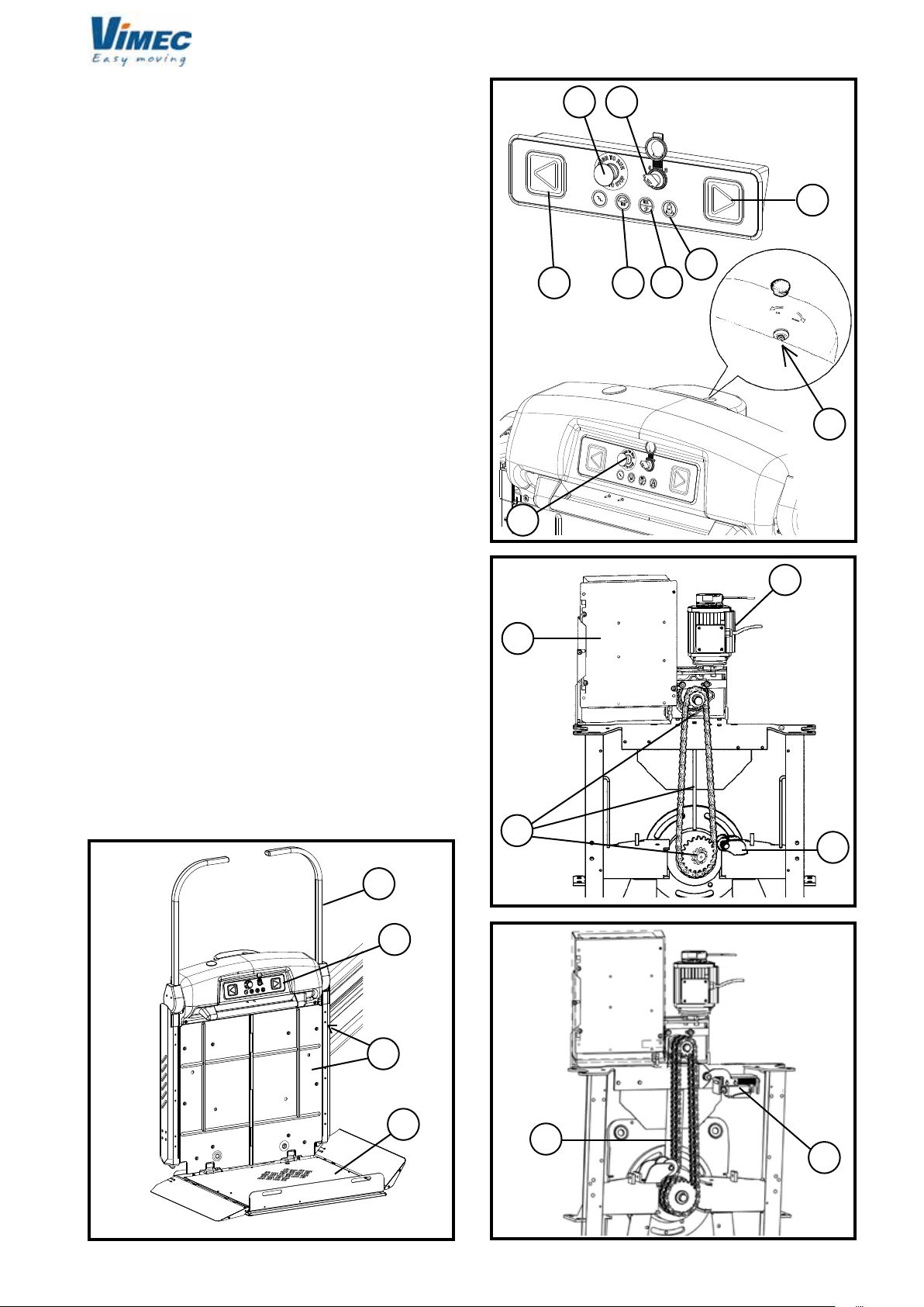
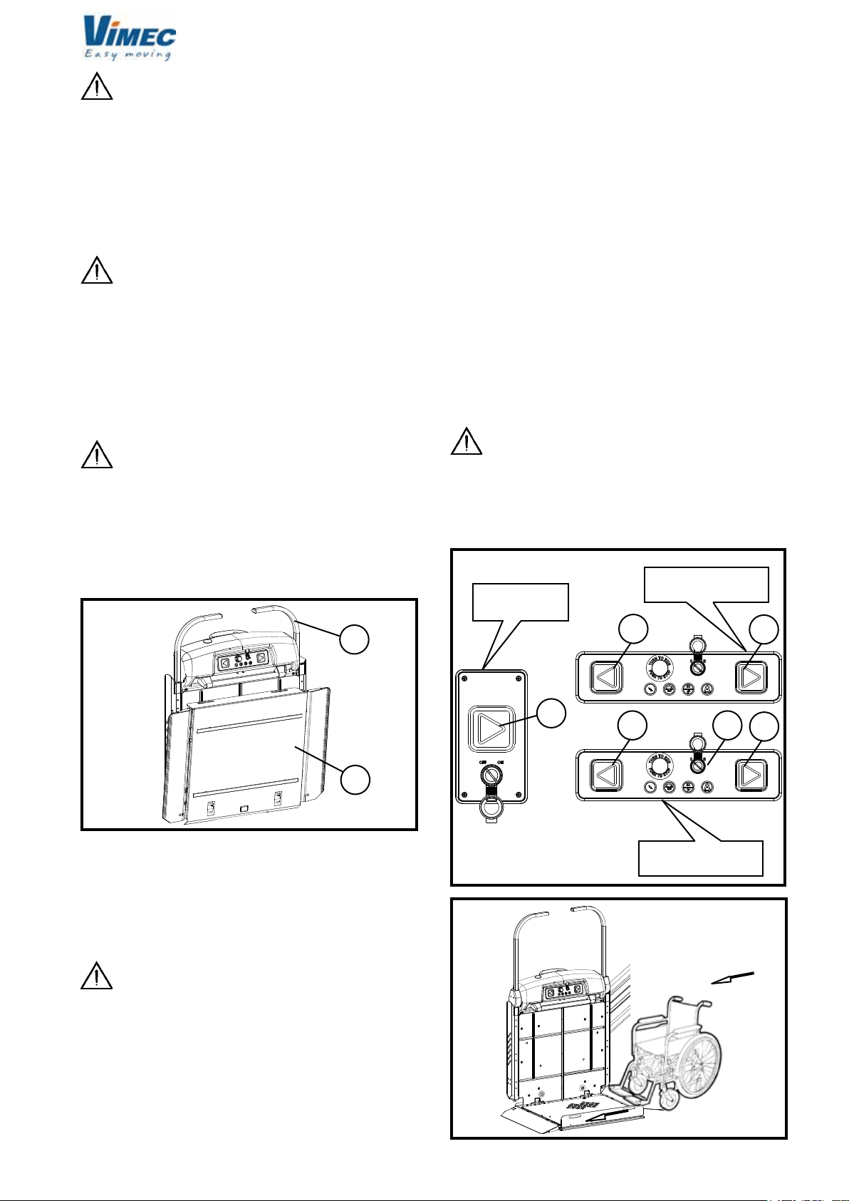
4) Press the up button (Fig. 9/c); the guards and bars
automatically move to the safety position and the stai-
rlift sets off.
5) B.R. - B.I. Version. At the destination oor, the stairlift
stops; if the up button is kept pressed, the bars and the
guard facing in the up direction automatically move to
the drive-off position. The guard facing in the down
direction is locked in the safety position, to ensure the
wheelchair can leave and return to the stairlift in safety.
6) Azionando il pulsante di discesa (Fig.9/b) le barre
e la bandella rivolta verso la salita si dispongono in
posizione di sicurezza e la macchina parte.
7) Al piano di arrivo la macchina si ferma e tenendo
premuto il pulsante di discesa (Fig.9/b) le barre e le
bandelle automaticamente si dispongono in posizione
di sbarco.
8) Disporre la macchina nelle condizioni di partenza
(con pedana chiusa e barre in posizione di riposo)
(Fig.8) disinserire ed estrarre la chiave.
N.B: Le barre e le bandelle sono meccanicamente
bloccate per tutto il percorso tra i piani.
WARNING: Pressing two buttons simulta-
neously, whether on the board on the stairlift or the
board at the oor, is strictly prohibited.
WARNING: The person transported must
always remain in the recommended position, with
the wheelchair brakes on, if the wheelchair is elec-
tric, turn it off, as long as transport is in progress.
The feet must be kept on the wheelchair foot-rest
and the free hand on one of the platform handle
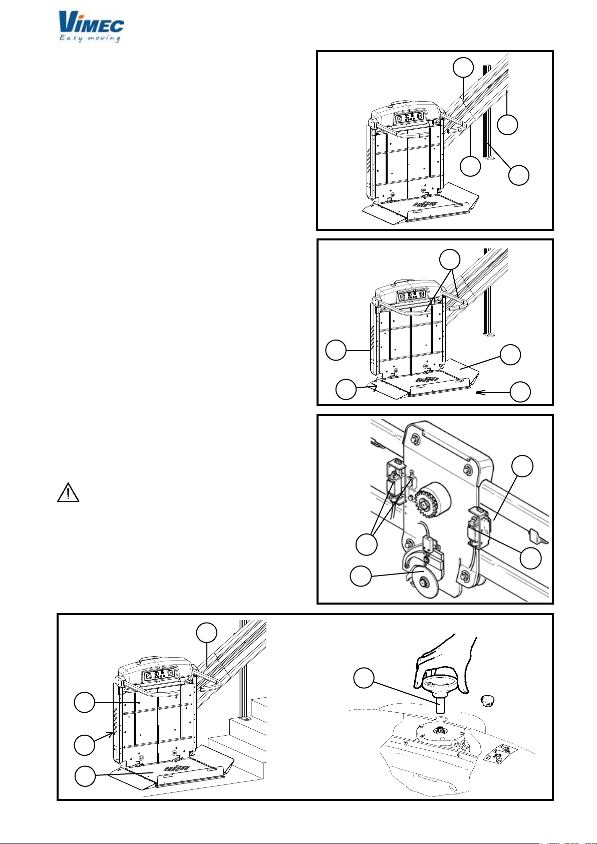
(Fig. 11/c).
WARNING: The person transported must
always look in the travel direction and must stop
the stairlift immediately if there is anyone on the
travel route.
WARNING: During operation of the stairlift
the landings and travel route must always be illu-
minated (minimum 50 Lux measured at oor level).
WARNING: Use of the stairlift by unau-
thorised persons is not permitted. The key which
enables use of the stairlift must always be kept in
a safe place and access to it may only be permitted
to authorised persons. The key must always be
removed at the end of each trip. Leaving the key
always in place is not permitted.
WARNING: Never leave the platform halfway
up the staircase.
ATTENZIONE: Never use the stairlift unless
a trained person is available to operate it in manual
mode in an emergency.
ATTENZIONE: Never place your hands or
any objects close to the rails or platform while the
stairlift is in motion.
ATTENZIONE: If the machine is installed
outside, cover it with a protection cloth after using
it. Remove the keys from the push-button panel and
close the rubber lid (Fig. 9/a).
Note for motor-operated platform
The device makes it possible to upset the platform by
an actuator.
The platform may be opened and closed by pressing
the button on the control board at the oor (Fig. 9/d).
A special manual device makes it possible to close the
platform in case of emergency:
1) Push the release button (located on the front body
towards the descent side) (Fig. 12/a) paying attention
to make a light pressure on the platform to avoid a
suddenly shutting.
2) Pull the platform gently, until the complete shutting.
3) Reset the normal functions of the equipment after
the emergency by a manual complete opening of the
platform.
WARNING: In the B.R. - B.I. Version, the
platform can only be operated with the down side
bar in the working position.
N.B: If the button on the control board at the oor
FIG.11
FIG.12
7512131

11
b
a
a
b
c
a
7511131
(Fig.9/d) is accidentally pressed when someone is on
the stairlift, a motor surge protector is tripped, stopping
the electromechanical actuator.
7.3) Stairlift operated by attendant.
If the person who uses the system is not self-sufcient,
the stairlift can be operated by an attendant, using the
special control board - Fig. 13.
The guiding person must follow the machine from
behind with respect to the moving direction.
7.4) Stairlift stopped at the other end of the staircase
(optional call - send function).
1) Insert the key in the control board at the oor and
turn it to ON - Fig. 9/a.
2) Keep the call or send button (Fig. 9/d) pressed until
the stairlift has reached its destination.
3) Remove the key from the control board, close the
rubber lid (Fig. 9/a).
WARNING: Never send/call the stairlift to a
oor unless the WHOLE travel route can be seen.
7.5) Manual operation in emergency
Skill level OC: Trained operator with specic skills
This emergency operating mode is used to bring the
person being transported to a oor in case of a power
black-out or a failure of the system.
WARNING: before operating in manual mode,
the operator MUST press the emergency switch (STOP)
(Fig. 2/e) and remove the key.
After pressing the emergency switch, proceed as
follows:
Moving the stairlift
1) Remove the central cap from the casing (Fig. 14/a).
2) Fit the handwheel provided (Fig. 14/b) into the hole,
tting it into the square shaft (Fig. 14/c) and turn the
handwheel to move the stairlift.
3) After reaching the oor, remove the handwheel and
close the cap again.
4) Restore normal operation of the stairlift once the
emergency conditions cease.
Releasing the safety arms in an emergency
1) Press the emergency STOP button.
2) B.I. (Independent bars), unscrew the two bar rele-
ase screws on the front of the stairlift body above the
handle (Fig. 15/a).
2) B.R. (Retractable bars), screws at the bottom on
the front have to be undone (one for each safety bar
- Fig.17/a).
3) Raise the bars by hand (Fig.15/b-16/b-17/b) and hold
them in position while the passenger gets off the stairlift.
4) Screw the release screws down again, holding the
bar in the working (lowered) position (Fig. 15/b).
5) Check that the bars are xed.
6) Reset the emergency STOP button.
WARNING: During the emergency operations
do not forget that the safety bars are not xed in
the opening position.
FIG.13
FIG.14
FIG.15
UP/DOWN
BUTTONS
DISABLED
BUTTONS
7512131
BARS
RELEASE
EMERGENCY

12
aa
b
a
a
b
a
a
b
b
7511131
WARNING: In case of a system failure or trip-
ping of the safety gear, call in an authorised VIMEC
technician. In case of any kind of malfunction, put
the stairlift out of use by turning the master switch
to OFF.
8) SAFETY SYSTEMS
8.1) Devices to prevent impacts and shearing along
the travel rails.
When in motion, the platform and the body of the stairlift
are protected by sensor guards which stop the stairlift
if it touches an obstacle of any kind - Fig. 5.
However, they do allow the stairlift to be moved in the
opposite direction to that in which the obstacle was
encountered, to allow removal of the obstruction.
8.2) Safety devices for the user.
a) Safety gear - Fig. 6/a.
The stairlift is equipped with a gradual action mechani-
cal safety gear. It is tripped if the drive components fail,
or if the normal downward travel speed is exceeded by
a pre-set amount.
When tripped, this device stops the stairlift.
WARNING: in this case the stairlift remains
locked out of use and an authorised VIMEC tech-
nician must be called in to put it back into service.
b) Bars and guard boards
During use the platform (Fig. 11/d) is protected by two
bars (Fig. 11/a) about 100 cm above the platform surfa-
ce. The platform is also protected by two guard boards
(Fig. 11/b) which have the dual function of facilitating
access to the stairlift at the oors (open position) and
of retaining the wheelchair while the stairlift is moving
(safety position at 50°, approximately 125 cm beyond
the platform surface).
Before the stairlift leaves the oor, the bars and guards
automatically move to the safety position.
The guard facing in the downward direction only opens
at the lower oor.
If the bars or guards encounter an obstacle as they
move into position, a surge protector is tripped, pre-
venting operation of the stairlift.
c) Handle
In the top of the stairlift body, it can be used as rest
while the stairlift is in motion - Fig. 11/c.
8.3) Other safety devices
a) Electrical and mechanical limit stops
The electrical limit switches (Fig. 18/a) tted to the stai-
rlift allow it to be stopped automatically in the correct
positions at each end of the stair. In case of problems,
an over-run safety stop device stops the stairlift - Fig.
18/b.
FIG.17
FIG.16
FIG.18
7512131

13
7511131
WARNING: in this case the stairlift remains
locked out of use and an authorised VIMEC tech-
nician must be called in to put it back into service.
b) Power supply
The stairlift is supplied at 230 V A.C. single-phase, while
the auxiliary circuit is supplied at 24 V D.C.
c) Controls
All controls are of the “dead man” type (the stairlift
stops if the nger is taken off the button). All the control
stations (on the stairlift and at the oors) are enabled
by a removable key (no-one can use the stairlift if the
key is not inserted).
WARNING: Pressing two buttons simulta-
neously, whether on the board on the stairlift or the
board at the oor, is strictly prohibited.
WARNING: Never use the stairlift if the con-
trols do not work in the “dead man” mode.
d) Operation by hand
The stairlift can always be operated by hand to bring the
person being transported to a oor in case of a power
black-out or a failure of the system (See point 7.5, it is
advisable to operate towards the lower oor).
e) Irreversible drive
The worm gear and spiral gear wheel ensure that the
stairlift cannot descend under its own weight and allow
smooth stopping.
f) Motor brake
The electric brake tted on the motor ensures quick
stopping and stability.
g) Emergency stop button
The control board on the stairlift is tted with a red
mushroom-head emergency STOP button (Fig. 2/e)
which stops all stairlift movements when pressed.
Stairlift operation is restored by turning the same button
clockwise through 45.
WARNING: Check monthly that the emergency
STOP button is working properly. If the STOP button
does not halt stairlift movements, DO NOT USE the
stairlift! Call in an authorised VIMEC technician
immediately.
7512131

14
7511131
9) MAINTENANCE
VIMEC products are built in compliance with the
current Machinery Directive, that emphasizes the
importance of safety both in designing and building
the machines, as well as of proper installation and
maintenance over time.
Therefore the product warranty is subject to an
ordinary and accurate maintenance of all safety de-
vices and guards. The maintenance service shall be
carried out by skilled technicians specially trained
for this task, in charge of performing the operations
described below.
WARNING: In all cases, call in only staff au-
thorised by VIMEC for servicing and repairs; use
only original spare parts.
WARNING: The recommended maintenance
frequencies must be complied with.
9.1) Parts requiring regular inspection
Skill level: OS - Specialist operator authorised by
VIMEC.
WARNING: Disconnect the power supply be-
fore starting maintenance, by turning the Master
Switch to OFF. Then padlock the box containing
the Master Switch.
Six-monthly checks:
a) Safety devices
Check that on contact with an obstacle, the anti-impact
and anti-shearing sensors stop the stairlift and allow it
to be started in the opposite travel direction.
Check that the stopping positions at the oors provided
by the limit switches are to requirements.
b) Electromagnetic brake
The electromagnetic brake on the motor must stop the
stairlift when fully loaded before the over-run device is
tripped. If necessary, replace the whole brake.
c) Drive mechanics
Check that the teeth of the drive sprocket and the
nylon wheels on which the stairlift runs are not worn or
damaged. There must be no grooves or attening on
the wheels. Check the chain and its stretcher device
for wear.
d) Safety gear
Check that the hook device is free to operate without
friction or excessive clearances and that it trips the
safety microswitch correctly.
To check operation of the safety gear, proceed as
follows:
- Move the stairlift 1-2 metres from the oor.
- Disconnect the power supply by turning the master
switch to OFF.
- Remove the protective panel (Fig. 1/b).
- Press the safety ear hook with a wooden/plastic rod.
WARNING: Keep well away from all unpro-
tected moving parts.
- Restore the power supply and press the down button
until the hook engages. The stairlift will stop when the
safety microswitch is pressed by the hook.
- Reset the safety gear by moving the stairlift upward
in manual mode (see point 7.5).
e) Stability of the rail
Check all the xing screws of the connections to the
mounts and all expansion plugs present.
f) General checks
Check all moving parts, the guards, labels and signs.
g) Rail cleaning
Make an accurate rail cleaning and waxing.
Annual checks:
a) Controls
Check their operation by trying out the stairlift in all
functions from on board (and from the control boards
at the oors if installed) in the working modes envisa-
ged.
Make sure that the system has not been tampered
with or modied.
WARNING: Retractable bars
Every 10.000 cycles, grease chain and shoes with
an anti-grip product.
7512131

15
a
7511131
9.2) Problem - Possible causes - Possible remedies
Skill level: O - Trained operator
10) WIRING DIAGRAMS
The electrical system diagrams are in the folder sup-
plied with the stairlift.
11) VIBRATIONS - AIRBORNE NOISE
a) Vibrations
The stairlift induces vibrations in the body and limbs of
the transported person having:
- low frequency and very low acceleration;
- short exposure times for the exposed person.
This parameter is therefore not signicant for safety
purposes.
b) Airborne noise: less than 70 dBA.
12) INFORMATION ON DISPOSAL OF SUBSTANCES
AND PARTS OF THE STAIRLIFT
a) Disposing of rubber and plastics
Place in clean containers and consign to disposal cen-
tres authorised as required by the regulations in force.
b) Oils and toxic materials
The stairlift does not contain oil or toxic materials.
FIG.19
7512131
13) BATTERIES FOR BUZZER OPERATION (EN
8140 VERSION)
A battery is available to power the buzzer for stairlift
operation (Fig. 19/a).
In case of power failure, the buzzer is tripped to
signal the problem.
Problem
The stairlift does not move in
either travel direction.
The stairlift moves downward
more quickly then cuts out.
The stairlift does not move from
either end of the stair.
The stairlift does not move in one
direction.
The stairlift hits the stop buffers.
Possible causes
Control enabling key.
Emergency STOP pressed.
Differential security breaker
tripped.
No power supply.
A safety device has been
tripped.
Safety gear tripped.
Over-run safety device
tripped.
Control enabling key.
Possible remedies
Turn the key to ON.
Turn the button clockwise through 45°.
Press the reset button. If it does not
remain in the ON position, call in an
authorised VIMEC technician.
Check the power supply; see point 7.5
(operating by hand).
Call in an authorised VIMEC technician.
Turn the key to ON.
Check that there are no obstacles acti-
vating the safety devices (Fig. 5/c-d-e).
Call in an authorised VIMEC technician.

16
7511131
CONTENTS OF THE MANUAL
1) System supply condition Page 17
2) Modular rails Page 18
3) Positioning the rail Page 19
4) Assembling the carriage Page 22
5) Complete actuator assembly Page 22
6) Assembling the bodywork Page 22
7) Assembling the platform with
driven front access Page 24
8) Assembling the platform Page 26
9) Connecting the electrical system Page 27
10) Checks on installation Page 27
11) Fitting the casings Page 27
12) Final testing Page 28
ASSEMBLY INSTRUCTIONS
7512131

17
a
a
b
a
b
c
b
a
b
d
d
b
a
7511131
1) SYSTEM SUPPLY CONDITION
The stairlift is supplied subdivided into the following
components:
Lift structure (Fig. 1/a)
Complete with gear motor, safety bars, drive compo-
nents and electrical system.
Carrier platform (Fig. 1/b)
Complete with guard boards and sensor base controlled
by safety microswitches.
Drive carriage (Fig. 2)
Complete with safety gear - Fig. 2/a.
Lift control board (Fig. 3/a)
With lift up/down buttons.
- Emergency push-button
- Bell push-button
Control board at oor (Fig. 3/b)
With lift up/down button.
Rail unit (Fig. 4)
Comprising:
- Complete rail constructed to measure (Fig. 4/a).
- Chain holder prole (Fig. 4/b).
- Cable and wire holder chain (Fig. 4/c).
- Feet for stairs (Fig. 4/d) (optional).
FIG.1
FIG.2
FIG.3
FIG.4
7512131

18
377,5 ± 0,25
b
b
a
a
7511131
2) MODULAR RAILS
The production of rail modules implies a xed position
of the connecting plates. In case of wall xing, no
additional operation is foreseen. But, in case of step
xing with feet (Fig. 5/a), if the feet position does not
match with the step centre, then a rearrangement is
required (Fig. 5).
2.1) Composition of modular rails
74 rail congurations are foreseen with nominal lengths
ranging between 1500 and 20000 mm.
Each conguration consists of one or more among the
following four rail modular elements:
- 0.8 M COMPLETE RAIL MODULE
nominal length equal to 800 mm and actual length of
791.4;
- 1.5 M COMPLETE RAIL MODULE
nominal length equal to 1500 mm and actual length
of 1470.56;
- 2.0 M COMPLETE RAIL MODULE
nominal length equal to 2000 mm and actual length
of 1979.6;
- 2.5 M COMPLETE RAIL MODULE
nominal length equal to 2500 mm and actual length
of 2488.64.
2.2) Composition of the rail
Every conguration is realized by assembling the ele-
ments and simply arranging the wider elements by their
lower rail side, and then shorter elements.
The following example claries the above explanation.
Rail with nominal length of 13750 mm (actual length:
13688 mm).
The rail consists of seven elements of four types ar-
ranged as follows:
1st module from the lower rail side
2.5 m module
2nd module from the lower rail side
2.5 m module
3rd module from the lower rail side
2.5 m module
4th module from the lower rail side
2.0 m module
5th module from the lower rail side
2.0 m module
6th module from the lower rail side
1.5 m module
7th module from the lower rail side
0.8 m module
2.3) Type of sheath
Four types of sheath are provided:
- Sheath for rails up to 3300 mm
- Sheath for rails between 3301 mm up to 6900 mm
- Sheath for rails between 6901 mm up to 14000 mm
- Sheath for rails between 14001 mm up to 20000 mm.
The “F” value (Fig. 8), or the drilling on the chain holder
prole, can vary depending on the position of the rail
connections, the xing screw (passing through the chain
holder prole) must not interfere with the rail connection.
2.2) Choosing the rail
To choose the rail conguration consider that the mini-
mum distance between the centre of gravity of the car-
riage and the rail ends must not be lower than 455 mm.
FIG.5
MAX. 1200
MAX. 500 MAX. 1200 MAX. 300
MIN. 200
7512131

19
a
100
7511131
FIG.7
FIG.6
Max.1 mm
3) INSTALLING THE RAIL
MODULAR OR STOCK RAIL:
- Following the dimensions shown on the assem-
bly drawing (see example in Fig. 5) specic to
each installation, place the rail in position of the
rail connections using the screws M8 x 25 (Fig.
5/a) (driving torque: 1,6 ÷ 2 DaNm).
- In case of rail junction, connect to plates (plates +
dowels with driving torque: 5 ÷ 6 DaNm - Fig. 5/b).
- If the feet (optional) are envisaged, x them to the
oor or on the stairs - Fig. 6/a.
- When mounting a rail without stair steps, supported
by the wall-mountings only, use the positioning feet
provided (accessories for the installation technician).
- After xing the feet (if any) and checking the project
dimensions (Fig. 8) prearrange the wall attachments
(shim with washers to reach the minimum dimension
100 mm) and x by inserting the expansion plugs pro-
vided (Fig. 7).
N.B.: maximum atness error on 4 connecting points
of 1 mm.
ASSEMBLY DRAWING AND RAIL
POSITIONING DIMENSIONS
FIG.8
CAPTIONS:
A: distance from lower rail side compared to the rst
raiser
B: distance between the lower rail side and the lower
landing oor
C: height under the rail
D: rail regression compared to the last raiser
E: distance between the lower rail side and the upper
landing oor
F: xing point of the cable holder chain
G: distance between the last upper connection and the
upper rail side
L: total rail length
L1: lower foot height
L2: height of feet placed on the steps
α : rail angle
T: Total steps
7512131

20
L=
7511131
PLATFORM
WIDTH
A (new) = A (table) +
measured raiser - 170
tan (alpha)
A (new) = A (table) -
170 - measured raiser
tan (alpha)
A + tot steps - D
cos (alpha)
If the rst raiser measured is lower than 170 mm:
“A” values are calculated considering the rst raiser
of 170 mm.
If the rst raiser measure is very different from the
theoretic value used for the calculations (170 mm),
the “A” value must be recalculated according to the
following formula:
If the rst raiser measured is higher than 170 mm:
This table can be only used with alpha angle higher
than 20 degrees. Below 20°, it is necessary to carry
out a special study according to the type of staircase.
In case of angles lower than 20°, please contact Vimec
to receive soon the rail installation data.
7512131
This manual suits for next models
1
Table of contents
Other vimec Stairlift manuals