vimec V65 B.I. User manual

11 - 03 - 2011
Vimec s.r.l
Via Parri, 7 - 42045 Luzzara - Reggio Emilia- Italy
Tel. + 39 0522 970 666 - Fax. + 39 0522 970919
www.vimec.biz
STAIRLIFT
V 65 ELECTRONIC
MODEL
B.I. - INDEPENDENT ARMS
B.R. - RETRACTABLE ARMS
USE AND MAINTENANCE Pages 03 - 17
INSTALLATION INSTRUCTIONS Pages 18 - 42
PARTS CATALOGUE Pages 43 - 83
MANUAL CODE
7 5 1 2 0 4 0 / g
VIMEC reserves the right to make modications and changes to its products at any moment in response to developments in
technology.
DATE ____________ APPROVED ____________
Original instructions

31/01/2010
Example
7502040
VIMEC S.r.l. “Original” Declaration of Conformity
_________________________________________________________
“EC” DECLARATION OF CONFORMITY
The manufacturer:
Via Parri n.7 , 42045 Luzzara (R.E.) ITALIA
Tel. 0522/970666 r.a. Fax 0522/970919
(Name and address of the person authorised to compile the technical le:
Name: Marco Marchetti
Address: Via Parri n.7 , 42045 Luzzara (R.E.) ITALY - Tel. +39/0522/970666)
states on his own responsibility that the stair lift for users on a wheelchair type:
V65 – B.I. – B.R. – Serial Number:
complies with the following Directives:
- Directive 2004/108/EEC “Electromagnetic Compatibility”
- Directive 2006/95/EEC “Low Voltage”
- Directive 2006/42/EEC “Machinery Directive”
The Legal Representative
Ing. Giuseppe Lupo
Luzzara

3
7502040
ENSURING SAFETY AT WORK
WARNING
This symbol highlights some essential safety instructions
Compliance with these instructions does not mean that the others can be ignored.
Read this manual carefully before installing, starting up, using and maintaining the lift.
The most important factor in preventing accidents is care and attention when using the lift.
Comply with the information provided on the signs of all kinds applied to the lift.
Replace damaged signs immediately.
All work on the lift except for normal operating procedures must be carried out by professionals.
Comply with the skill levels specied for the various procedures, symbolised as follows:
O Trained operative
TO Trained operative with specic skill
SO Skilled operative authorised by the manufacturer
The lift must always be operated by an ADULT familiar with all the operating functions and precautions
described in this manual.
CONTENTS OF THE MANUAL
1. Unit and manufacturer identication Page 04
2. After-Sales Service Page 04
3. Description of unit Page 05
4. Technical data Page 08
5. Intended and improper uses Page 09
6. Preparing the lift for operation Page 09
7. Correct use of the stairlift in independent arm and retractable arm versions Page 10
8. Safety systems Page 13
9. Maintenance Page 15
10. Electrical wiring diagrams Page 17
11. Vibration – Airborne noise levels Page 17
12. Information on the disposal of materials and unit parts Page 17
USE AND MAINTENANCE

4
I - 42045 Luzzara (RE)
Via Parri,7 - Tel. + 039 0522 970 666
7502040
1) UNIT AND MANUFACTURER IDENTIFICATION
2) AFTER-SALES SERVICE
DEALER’S STAMP AND AUTHORISED
AFTER-SALES SERVICE CONTACT DETAILS
SERIAL NUMBER
_ _ _ _
SERIAL NUMBER
_ _ _ _
WORKING LOAD
- - - kg
TYPE V65
SERIAL NUMBER (Nr) - - - -
YEAR OF MANUFACTURE - - - -
WORKING LOAD (Kg) - - -
POWER SUPPLY (V / A / Hz) 230 / 5 / 50

5
a
c
b
d
f
bc d
a
e
h
g
i l n
m
7502040
3) DESCRIPTION OF THE UNIT
3.1) Description
Car - Fig. 1
Comprises:
- carriage.
- frame.
- protection arms- Fig. 1/a.
- platform - Fig. 1/c.
- casing - Fig. 1/b.
- control panel - Fig. 1/d.
Contains:
The control panel carries the following:
- controls on/off key - Fig. 2/a.
- up/down control buttons - Fig. 2/b.
- arm and platform control buttons - Fig. 2/c.
- oor selector buttons - Fig. 2/d.
On the car:
- red “mushroom” emergency stop button - Fig. 2/e.
- handwheel connection for manual operation - Fig. 2/f.
- man-machine interface display (optional) - Fig. 2/g.
- start push-button - Fig. 2/i
- overload indicator light - Fig. 2/l
- oor indicator light - Fig. 2/m
- bell push-button - Fig. 2/n
- display setting keypad (optional) - Fig. 2/h.
FIG.2
FIG.1

6
a
c
b
b
c
b
a
d
b
b
a
c
b
b
b
c
de
b
a
7502040
- on/off key or button - Fig.2/i.
- motor - Fig. 3/a.
- transmission components - Fig. 3/b (units with gra-
dient < 20°).
- electric system - Fig. 3/c.
As an option, the machine can be also supplied
complete with double drive chain (Fig. 3 bis) and
micro-chain (Fig.3 bis).
Track - Fig. 4
Comprises:
- Rail - Fig. 4/a.
- Wall mounts - Fig. 4/b.
- Charging station or busbar - Fig. 4/c.
- Step feet (optional) - Fig. 4/d.
3.2) Main mechanical safety features
- Protection arms - Fig. 5/a.
- Safety aps - Fig. 5/b.
- Sensitive edges providing anti-collision and anti-
shearing protection on lift body - Fig. 5/c.
- Sensitive edges providing anti-collision and anti-
shearing protection on platform - Fig. 5/d.
FIG.5
FIG.3
FIG.4
FIG.3 bis

7
a
a
b
c
d
e
f
7502040
FIG.6
FIG.6 bis
FIG.7
- Underpan sensors providing anti-crushing protec-
tion - Fig. 5/e
- Mechanical safety gear - Fig.6/a.
3.3) Main electrical safety features
Protection against overcurrent, overload, acciden-
tal contacts, and direct and indirect contacts.
- Differential circuit breaker on power supply system.
3.4) Warning signs
The lift is tted with various warning signs:
- Emergency switch must be pressed before operation
by hand - Fig. 2/e.
- Lift dataplate.
- Manual arm and platform release sign.
3.5) Supply package
- Track and mounting connections - Fig.7/a.
- Frame with carriages - Fig. 6 and Fig.7/b.
- Set of arms- Fig. 7/f.
- Platform - Fig. 7/c.
- Casing - Fig. 7/d.
- Handwheel for manual operation - Fig. 7e.
The lift system must be installed by skilled
staff authorised by VIMEC.

8
7502040
4) TECHNICAL DATA
- Drive system
Worm gear reduction unit Ratio 1/40
- Operating data
Travel direction Forward/backward
Speed (ascent/descent) 0.15 m/s
Capacity 1 person
Gradient from 0° to 50°
Working load 250 kg. up to 45°
200 kg. up to 50°
- Duty cycles
Duty 20 min/hour max
- Ambient conditions
Temperature From -10°C to +60°C (suggested and
recommended).
Humidity maximum 70% (use in bathrooms and
swimming-pools is not permitted)
(suggested and recommended).
- Electrical System
Drive motor 24 V d.c. 1 kW
Power absorption 40 A
- Controls
Up/down control button Hold-to-run type
Emergency stop button with detent
Key-switch
3.6) Reference technical standards
The machine complies with the following Directives:
- Directive 2004/108/CEE “Electromagnetic Compa-
tibility”
- Directive 2006/95/CEE “Low Voltage”
- Directive 2006/42/CEE “Machinery Directive”

9
7502040
5) INTENDED AND IMPROPER USES
5.1) Intended Uses
The stairlift is a system for transporting passengers SEATED IN A WHEELCHAIR OR ON A SPECIAL SEAT
(optional), suitable for installation on staircases having the following characteristics:
- Location: Indoors and outdoors
- Steps: Parallel
- Gradient: Minimum 0° - Maximum 50°
Intended user: The intended user is self-sufcient and physically and mentally capable, familiar with
the lift’s operations and the use and maintenance instructions.
WARNING: If the person using the lift is not self-sufcient, it must be operated by another per-
son (their attendant). When the lift is motion remain seated and do not move or rock.
5.2) Improper Uses
- Transportation of objects on the lift platform
- Overloading of the lift (for example, a disabled person in an electric wheelchair weighing more than
the maximum permitted working load). See section 4, Technical Data)
- Use of the lift by unauthorised persons (for example children, or people who do not meet the re-
quirements stated in point 5.1)
Improper Uses Problems
Use on stairs with gradients over 50°: Motor overheats
User standing on platform: Falling hazard
Operation by unsuitable user: Falling hazard
Transportation of more than one person: Falling hazard, motor may overheat
WARNING: NEVER MAKE MODIFICATIONS TO THE LIFT FOR ANY PURPOSE, DO NOT PLACE
EXTRANEOUS OBJECTS OR LIQUIDS IN HOLES OR OPENINGS, DO NOT SPRAY LIQUIDS AT THE
LIFT
6) PREPARING THE LIFT FOR OPERATION
6.1) Preliminary Checks
Checks to be performed before the lift is put into service
Skill level required: SO - Skilled operative authorised by the manufacturer.
ITEM CHECKED OUTCOME OF CHECK
Controls: Lift responds correctly to controls
Emergency stop working effectively
Safety devices: Check that safety devices are tripped, stopping the lift
- Sensitive edges
- Electric limit switches
- Final limit switches
- Anti-crushing underpan sensor
Power supply: 230 V - 5A - 50/60 Hz.
Earth connection: Check that the system’s earth is connected to the mains
circuit earth.

10
b
a
b
f
e
d
c
g
a
h
c
g
c
e
b
d
7502040
7) CORRECT USE OF THE STAIRLIFT IN INDEPEN-
DENT ARM AND RETRACTABLE ARM VERSIONS
WARNING: READ THIS MANUAL CAREFULLY
BEFORE USING THE LIFT. The lift must only be
used in accordance with the intended uses descri-
bed in section 5.
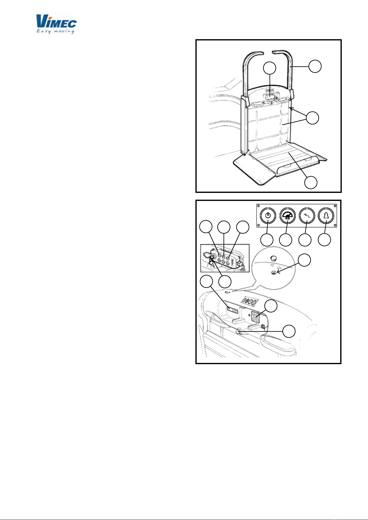
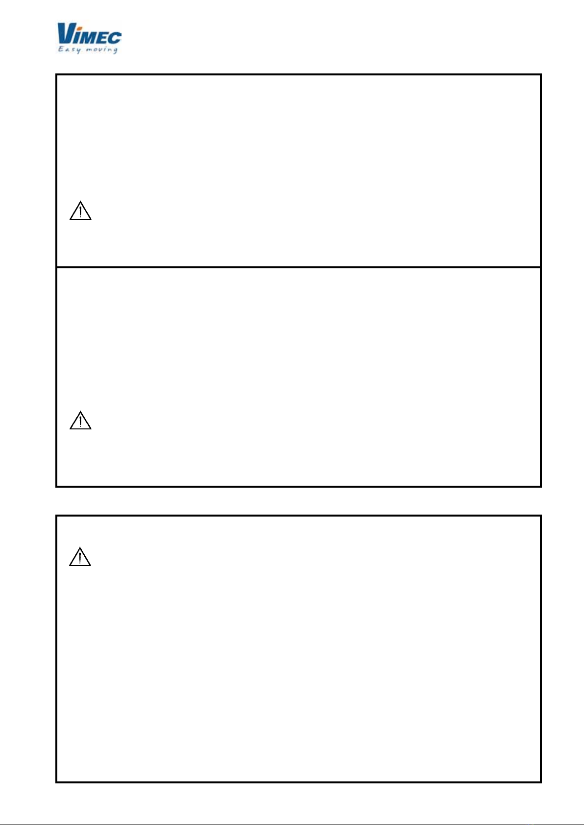
7.1) Starting position
Lift parked at one end of the staircase with the platform
raised (Fig. 8/a) and the arms in the rest position (Fig.
8/b) with the master key (if any) turned to ON; the lift
is powered up.
- Version without on/off key
In this case the lift switches itself off automatically after
2 hours if it is left off the charging station or in the event
of a mains power failure. To switch it back on, simply
press the on/off button on the upper casing.
7.2) Using the stairlift
WARNING: Always keep the access to the
platform and master switch unobstructed.
NEVER overload the lift.
1) For lifts with manual platform (standard)
- Move the arm on the descent side into the working
position by pressing the button (Fig. 9/e) on the con-
trol panel on the lift or at the oor (optional).
- Lower the platform by hand.
- If the lift is at the bottom oor, return the descent side
arm to the rest position (Fig. 9/b) to allow the wheel-
chair to move onto the platform.
1) For lifts with motor-operated platform (optional)
- Insert the key (Fig.9/a) on the control panel on the lift or
at the oor (optional) and turn it to (1) ON. - Fig.9/g.
- Open the platform by pressing the button provided
(Fig. 9/e).
The ap sets in the embarkation position with the de-
scent side arm in the working position.
If the lift is at the bottom oor, return the descent side
arm to the rest position to allow the wheelchair to move
onto the platform.
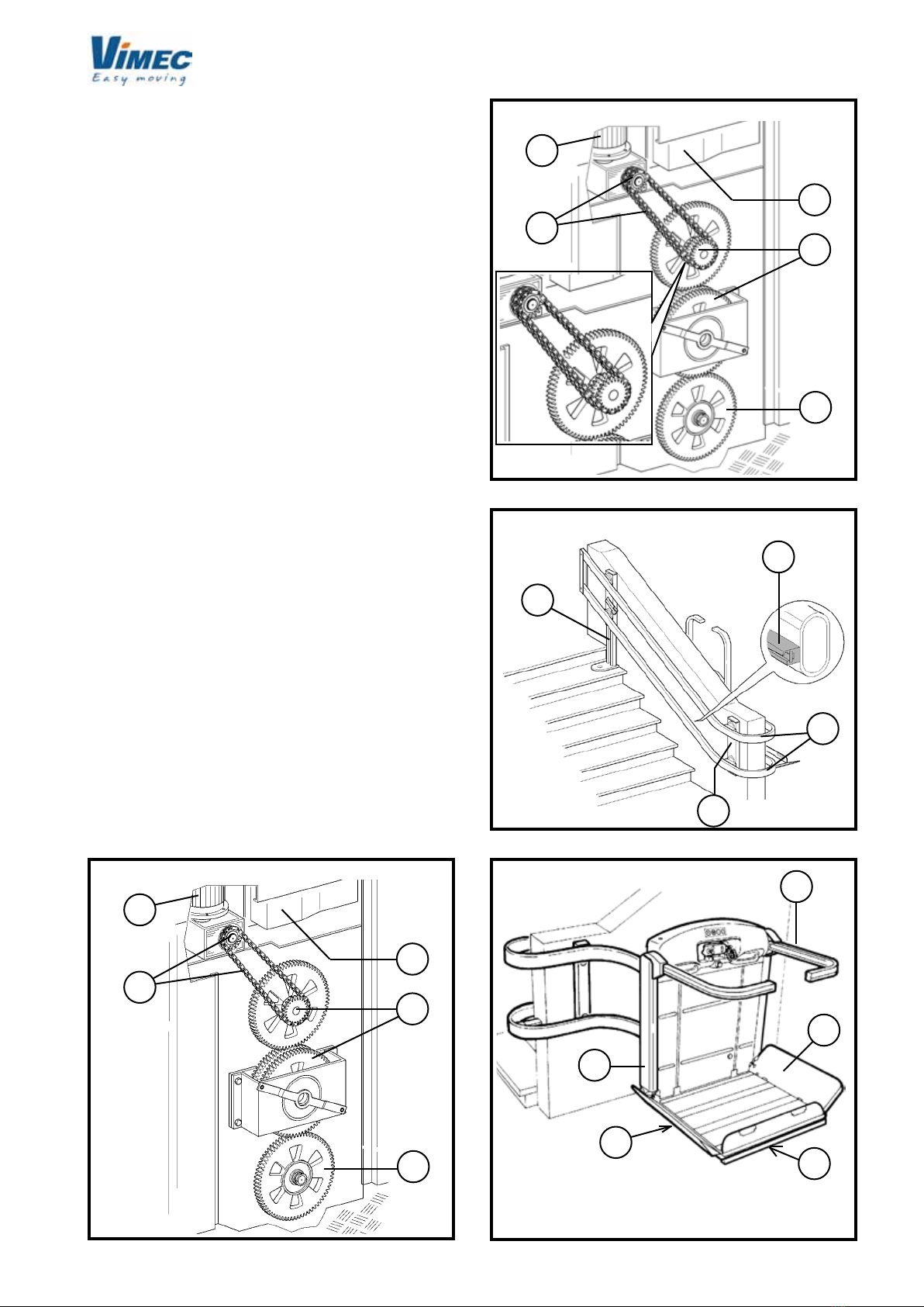
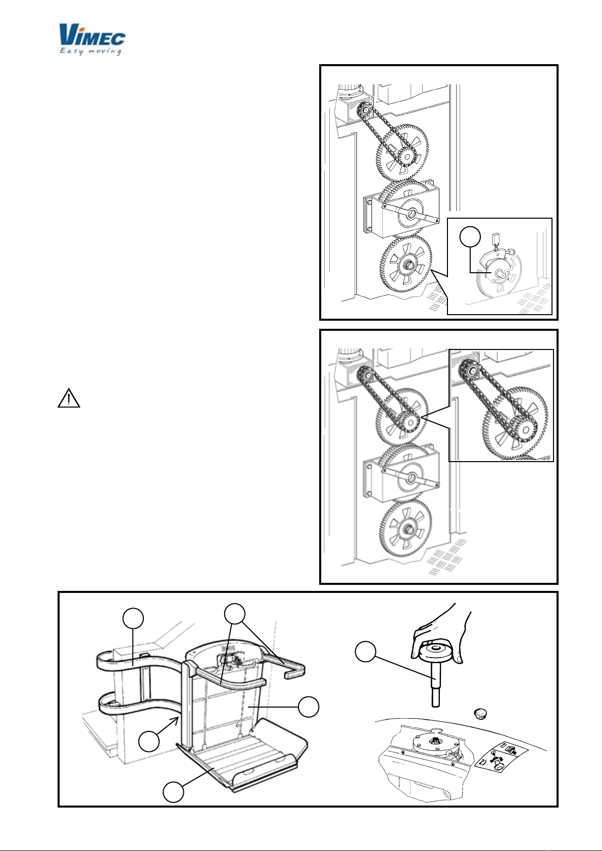
2) Get onto the platform, facing in the travel direction
and positioning yourself centrally (Fig.10) to allow the
ap to provide its pressure-sensitive safety function.
Engage the wheelchair’s brakes; if it is electric, switch
it off.
WARNING: When positioning the wheelchair
on the platform, make sure that no part of the body
or wheelchair can project beyond its edge. When
the lift is motion remain seated and do not move
or rock.
3) Insert the key (Fig.9/a) on the control panel on the
lift (Fig. 9/g) and turn it to (1) ON.
4) Press the up button (Fig. 9/c); the aps and arms
automatically locate in the safety position and the lift
starts.
N.B.: Press the button (Fig. 9/f) to select the oor
(e.g. press once to select the rst intermediate oor,
press twice for the second).
In stairlifts with an intermediate stop, the green led on
the pushbutton panel (Fig. 9h) and the one on the ca-
sing in a central position (Fig. 8c), blink when the stop
is reached. Therefore, if the intermediate stop is not
preselected, and you wish to stop there, release the
button when you see the green light blinking.
5) The lift stops at the destination oor; release the up
button and press it again and the arm and ap on the up
side automatically move to the disembarkation position.
The ap and arm on the down side are now locked in the
safety position, ensuring safety during disembarkation
and when the next passenger embarks.
FIG.8
FIG.9
FIG.10
FLOOR PLATFORM

11
a
c
b
a
bd
a
7502040
6) When the down button (Fig. 9/d) is pressed the ap
and arms on the up side automatically locate in the
safety position and the lift starts.
7) The lift stops at the destination oor; keep the down
button (Fig. 9/d) pressed and the arm and aps auto-
matically move to the disembarkation position.
8) Return the lift to its original condition (platform up
and arms in rest position) (Fig. 8), and turn the key to
OFF and remove it.
N.B.: The arms and aps are mechanically locked in
position as long as the lift is between oors.
WARNING: The passenger must always remain
in the recommended position, with the wheelchair’s
brakes on, and electric wheelchairs switched off, as
long as the lift is in motion. The passenger should
have his feet on the wheelchair footrest and his free
hand on one of the platform handles (Fig. 11/c).
WARNING: The passenger must always look
in the travel direction and must stop the stairlift
immediately if there is anyone on the track.
WARNING: During operation of the stairlift,
the landings and track must always be well lit (at
least 50 Lux measured at oor level).
WARNING: Use of the stairlift by unauthorised
persons is not permitted. The key which enables
operation of the lift must always be kept in a safe
place and must only be accessible to authorised
persons. The key must always be removed at the
end of each journey. The key must not be left in
the switch.
WARNING: Never leave the platform halfway
up the stairs.
WARNING: Never use the lift unless a trained
person is nearby to operate it by hand in an emer-
gency.
WARNING: Never place hands or objects on
or near the rails or platform while the lift is in mo-
tion.
WARNING: If the lift is installed outdoors,
always place its protective cover over it after use.
Remove the keys from the control panels and close
the rubber cover (Fig. 9/a).
Note for motor-operated platforms
The device tips up the platform by means of an elec-
tromechanical actuator.
The platform is lowered and raised by means of the
buttons provided on the control panel on the lift, and the
panels at the oors if installed (Fig.9/b) and (Fig.9/e).
There is a manual devices for raising the platform in
emergencies:
1) Press the release button (Fig.12/a), holding the plat-
form gently to prevent it from closing too sharply.
2) Hold and guide the platform until fully raised.
FIG.11
FIG.12
3) Restore the lift to normal operating status at the
end of the emergency by fully opening the platform
by hand.
WARNING: The platform can only be raised
or lowered with the descent side arm in working
position.
N.B: If the platform up button is accidentally pressed
with someone on board the lift, a motor overcurrent
device is tripped and cuts out the electromechanical
actuator. The device resets automatically when the
button is released.

12
a
b
c
b
aa
7502040
7.3) Lift operated by attendant
If the person using the lift is not self-sufcient, it must
be operated by another person (their attendant), who
will use the same control panel - Fig. 9.
The attendant will follow the lift up or down the stairs
on foot.
7.4) Lift stopped at other end of the staircase (op-
tional call – send function)
1) Insert the key (Fig.9/a) on the control panel at the
oor and turn it to “ON”.
2) Keep the call or send button (Fig. 9/c) and (Fig.9/d)
pressed until the lift arrives at destination.
3) Remove the key from the control panel and close
the rubber cover (Fig. 9/g).
WARNING: The call/send function only works
with the platform fully raised.
WARNING: Never send/call the lift to/from a
oor unless you can see the WHOLE of the track.
7.5) Lift with seat for transporting a seated pas-
senger (optional)
WARNING: the seat is able to take a maximum
weight of 115 kg. While the lift is in motion, the pas-
senger must always remain in the position shown in
Fig. 13 and must always keep their free hand on one
of the arms. After use, raise the folding seat and set
the lift as described in 7.2-8 (Fig. 8).
7.6) Emergency manual operation
Skill level TO: Trained operative with specific
skill.
Manual emergency operation allows the passenger to
be brought to a oor in the event of a power blackout
or system failure.
WARNING: Before operating the lift in manual
mode, it is ESSENTIAL to press the emergency button
and remove the key (Fig. 9/a).
Proceed as follows:
Moving the lift
1) Remove the cap from the centre of the casing (Fig.
14/a)
2) Fit the handwheel supplied (Fig. 14/b) into the hole
and onto the square shaft (Fig. 14/c), then turn the
handwheel to move the lift.
3) At the destination oor, remove the handwheel and
replace the cap.
4) Restore the lift to normal operating status at the end
of the emergency.
5) Bring the lift to the “home” oor (reset) to reset its
programming.
Releasing the safety arms in an emergency
1) Press the emergency STOP button.
2) B.I. (Independent arms), unscrew the two arm
release screws on the front of the lift body above the
handle (Fig. 15/a)
2) B.R. (Retractable arms), screws at the bottom on
the front have to be undone (one for each safety arm
- Fig.16/a).
3) Raise the arms by hand (Fig.15/b-16/b) and hold
BARS
RELEASE
EMERGENCY
FIG.15
FIG.13
FIG14

13
a
a
b
a
7502040
them in position while the passenger gets off the
lift.
4) Screw the release screws down again, holding
the arm in the working (lowered) position (Fig.
15b).
5) Check that the arms are xed.
6) Reset the emergency STOP button.
WARNING: Remember that during emergency
operation the arms do not lock in the raised position.
Operations 4 to 6 must be carried out by an
authorised VIMEC technician.
WARNING: In the event of a system failure or
if the safety gear is tripped, call in the VIMEC au-
thorised after-sales service. In the version without
key, the lift switches off when the STOP button is
pressed.
8) SAFETY SYSTEMS
8.1) Safety devices to prevent collisions and shear-
ing along the track
The platform and the body of the lift are protected while
in motion by sensitive edges which cut out lift travel on
contact with any obstacle - Fig. 5.
They allow the lift to travel in the direction opposite to
the one in which the obstacle was encountered, in order
to move it off the track.
8.2) User safety
a) Safety gear - Fig. 6/a.
The lift is equipped with a mechanical safety gear. It
comes into operation if a drive component fails or if
the lift reaches a preset above-normal speed during
descent.
This device gradually slows the lift to a standstill.
WARNING: in this event the lift cuts out per-
manently and a VIMEC authorised technician must
be called in to put it back into operation.
b) Arms and Flaps
The platform (Fig. 11/d) is protected during use by two
arms (Fig. 11/a) about 100 cm above its oor level. In
addition, the platform is protected by two aps (Fig.
11/b) which have the dual function of acting as access
ramps at the oors (when lowered) and holding the
wheelchair in place while the lift is in motion (safety po-
sition at 50°, about 155 mm above the platform oor).
The arms and aps automatically move to the safety
position before the lift leaves the oor.
The ap facing towards the bottom of the staircase only
opens at the bottom oor.
If the arms or aps encounter obstacles, a microswitch
is tripped, cutting on the current lift function. Release
the button to restore operation.
c) Handles
In the top of the stairlift, they are used for additional
stability while the lift is in motion - Fig. 11/c.
8.3) Other Safety Devices
a) Limit switches and limit stops
The “home” sensor acts as limit switch at the bottom
oor. The positions of the other oors, including the top
oor, are programmed by means of encoders. In the
event of a malfunction, an additional nal limit switch
stops the lift - Fig.17/a.
WARNING: in this event the lift cuts out per-
manently and a VIMEC authorised technician must
be called in to put it back into operation.
FIG.17
FIG.16

14
a
a
a
7502040
b) Power supply
The power supply is 220 V~ input from the mains and
27 VDC as output on the busbar or at the charging
stations.
The battery on the lift is at 24 VDC.
All power and auxiliary circuits are supplied at 24
VDC.
c) Controls
All controls are of hold-to-run type
(the lift stops as soon as the nger is removed from
the button).
All the control panels (on the lift and at the oors) are
enabled by a removable key (no-one can use the lift
unless the key is inserted).
WARNING: Do not use the lift if the controls are
no longer operating on the hold-to-run principle.
d) Operation by hand
The lift can always be operated by hand to bring the
passenger to the oor in the event of a system failure
or power blackout.
e) Non-reversible drive
The spiral worm reduction gear ensures that the lift
cannot descend under its own weight, and ensures a
smooth stop.
f) Motor brake
The electric brake tted on the motor ensures quick,
stable stopping.
g) Emergency stop button
The lift is fitted with a red emergency STOP but-
ton (Fig. 2/e) which cuts out all lift movement when
pressed.
To restore operation of the lift, turn the emergency but-
ton 45° clockwise.
WARNING: Check operation of the emergency
STOP button every month. If the STOP button does
not cut out all lift movements, DO NOT USE the lift !!
Call in an authorised VIMEC technician at once.
WARNING: If the lift is to be out of use for
a long time or the power supply is disconnected,
turn the key (Fig. 18/a) to OFF so that the batteries
do not discharge.
On machines without on-off key, this operation is
not necessary (the lift switches itself off automa-
tically after 2 hours if it is left off the charging station
or in the event of a mains power failure).
WARNING: If the stairlift is not used for a
long period of time, connect the power supply to
the mains for at least 12 hours every month to keep
the batteries charged.
FIG.18
FIG.19
FIG.20

15
7502040
9) MAINTENANCE
VIMEC products are built in compliance with the current
Machinery Directive, that emphasizes the importance of
safety both in designing and building the machines, as
well as of proper installation and maintenance over time.
Therefore the product warranty is subject to an ordinary
and accurate maintenance of all safety devices and
guards. The maintenance service shall be carried out
by skilled technicians specially trained for this task, in
charge of performing the operations described below.
9.1) Precautions for long periods of disuse:
If the stairlift is to be left unused for a long time, switch
on the power supply to charge the batteries at least
every month.
WARNING: In all circumstances, only call in
authorised VIMEC after-sales staff for service and
repairs; use only genuine spare parts.
WARNING: Maintenance frequencies must be
complied with.
9.2) Parts requiring regular inspection
Skill level required: SO: Skilled operative authorised
by VIMEC.
WARNING: Before starting servicing work on
the rail or lift, disconnect the electricity by pulling
the power supply plug (Fig. 19/a) and taking care to
disconnect the battery on the lift. (Fig. 20/a).
Monthly checks:
WARNING: If the lift is used for more than 30
trips per day, check the mechanical drive compo-
nents, safety devices and parts subject to wear
and tear.
Six-monthly checks:
a) Safety devices
Make sure that on contact with an obstacle the anti-col-
lision and anti-shearing sensors stop the lift and allow
it to be restarted in the opposite direction.
Check that the lift stops in the required positions at
the oors.
b) Checking the interlocking of the platform
with independent or retractable arms (manual
platform)
Check that as long as the descent side arm is in the
rest position the platform remains locked, whether in
the working or the rest position.
c) Electromagnetic brake
The electromagnetic brake on the engine must stop
the lift, carrying the maximum working load, before the
nal limit switch is tripped. If necessary, replace the
whole brake unit.
d) Drive mechanics
Check that the drive sprocket teeth and the lift’s nylon
wheels are not worn or damaged. There must be no
scoring or attening of the wheels. Check the chain
for wear.
e) Safety gear
Check that the hook operates freely without friction or
excessive play, and trips the safety microswitch cor-
rectly.
To check that the safety gear is operating correctly,
proceed as follows
- Move the stairlift away from the oor (1-2 metres).
- Cut off the electricity by turning the master switch to
OFF.
- Remove the protective panel (Fig. 1/b).
- Press the safety gear hook with a plastic/wooden
rod.
WARNING: Keep well away from all unpro-
tected moving parts.
- Restore the power supply and press the down button
until the hook engages. The stairlift will stop when the
hook depresses the safety microswitch.
- Reset the safety gear by moving the stairlift upward
by hand (see point 7.6 ).
f) Stability of the rail
Check all the xing screws which connect the rail to its
mounts and any expansion plugs used.
g) General checks
Check all moving parts, the guards, labels and signs.
Check the batteries and the warning lights of the power
supply unit.
h) Cleaning the rail
Clean the rail thoroughly.
Annual checks:
a) Controls
Check their operation by testing all the lift’s functions
using the control panel on the lift (and the control panels
at the oors, if installed).
Make sure that the system has not been tampered with
or modied.
b) Floor control panels
Check that these devices are operating correctly.
c) Electrical system
Check that all electrical components, contactors and
microswitches are operating correctly.
Check the continuity of the earth conductors.
Check that the lift does not tilt by more than 2°.Check
Check that the earth conductors are properly connected
to earth.

16
7502040
d) Testing for lifts with sections of rail having gradi-
ent of less than 20°
Move the lift to the area with gradient of more than 25°
and check that the cam tripping roller is 0.5÷1.5 mm
from the cam (see Fig. 64 page 41).
Then move the lift to the area with gradient of less than
20°, and place a weight of 250 kg on it with its centre of
gravity 150 mm from the edge (see Fig. 63 page 41).
Check that the lift does not tilt by more than 2°.
e) Check the tension of the drive chain and stretch it as
described at point 19 on page 40 if necessary.

17
7502040
9.3) Troubleshooting
Skill level required: O - trained operative
Problem Possible causes Possible remedies
The lift does not move in Controls on/off key Turn the key to “ON”
either direction
Emergency STOP pressed Turn the button clockwise through 45°
Differential circuit breaker Press the reset button. If it does not
tripped remain in the “ON” position, call an
authorised VIMEC technician.
Power supply failure Check the power supply; see point 7.6,
(Manual operation).
A safety device has been tripped Call a VIMEC authorised technician
The lift descends more quickly Safety gear tripped Call a VIMEC authorised technician
than usual then cuts out
The lift does not move from Final limit switch tripped Call a VIMEC authorised technician
the top or bottom of the stairs
Controls on/off key Turn the key to “ON”
The lift does not move in one Check for obstacles tripping
direction the safety devices Fig. 5/c-d-e
The lift is reaching the buffers Call a VIMEC authorised technician
at the top or bottom of the stairs
The lift cuts out and the The arms or underpan switch Switch the lift off and then back on
buzzer sounds have been excited 10 times with the key. When instructed to move,
in about 30 seconds the lift automatically returns to the
home oor. The lift responds correctly
to all subsequent controls
After the lift is switched on The lift has been switched off Wait for the lift to reach the home oor
and the start button is when not at the parking station
pressed, the lift moves to
the home oor
10) ELECTRICAL WIRING DIAGRAMS
The electrical wiring diagrams are in the folder supplied
with the lift.
11) VIBRATION – AIRBORNE NOISE LEVELS
a) Vibration
The lift causes vibration in the passenger’s body and
limbs with the following characteristics:
- low frequency, very low acceleration;
- short exposure cycles for the exposed person.
This parameter is therefore insignicant for safety
purposes.
b) Airborne noise: less than 70 dBA
12) INFORMATION ON THE DISPOSAL OF
MATERIALS AND UNIT PARTS
a) Disposing of rubber and plastics
Place in clean containers and consign to disposal cen-
tres authorised under the relevant regulations.
b) Oil and toxic materials
The lift does not contain any oil or toxic materials for
disposal.
c) Disposing of batteries
Consign batteries to authorised disposal centres or
dispose of them in accordance with the relevant regula-
tions in the country where the stairlift is installed.

18
7602040
INSTALLATION INSTRUCTIONS
CONTENTS OF THE MANUAL
1. System supply package Page 19
2. Installing the lower rail Page 20
3. Installing the upper rail Page 22
4. Fitting the carriage Page 23
5. Positioning the charging station (if applicable) Page 25
6. Connecting the power supply unit Page 27
7. Connecting the installation engineer’s control panel Page 27
8. Fixing the connecting feet Page 29
9. Fitting the arms Page 30
10. Fitting the platform with motor-operated front lift ap Page 31
11. Fitting the platform Page 34
12. Preparing the lift for setup Page 36
13. Setting up the lift Page 37
14. Post-installation checks Page 37
15. Adjusting rail bend rollers Page 38
16. Adjusting guide shoe supports Page 38
17. Fitting the nal limit switch cams Page 39
18. Check the position of the nal limit switch cam and plates Page 40
19. Stretching the chain Page 40
20. Final testing Page 40
21. Fitting the casing Page 41
22. Fitting the caps and end covers Page 42

19
b
a
b
b
c
a
d
d
c
de
7602040
1) SYSTEM SUPPLY PACKAGE
The system supply package consists of the following:
Main structure (Fig. 1/a)
Complete with gear motor, drive components with safety
gear and electrical system.
Batteries (Fig.1/e).
Platform (Fig. 1/b)
Complete with aps and underpan with safety micro-
switches.
Arm assembly (Fig. 1/c).
Fixed or retractable (optional) protective arms.
WARNING: Remove the arm assemblies (Fig. 1/c)
before tting the carriages onto the rails.
Casings and on-board control panel (Fig. 1/d).
WARNING: Remove the upper and lower casings
(Fig. 1/d) before tting the carriages onto the rails.
Rail assembly (Fig. 2)
Comprising:
- Lower rail complete with power bus bar for special
applications and supporting feet (Fig. 2/a).
- Upper rail (Fig. 2/b).
- Mounting accessories.
FIG.1
FIG.2

20
a
b
C
D
A
a
a
da
b
a
d
c
AB
160
7602040
2) INSTALLING THE LOWER RAIL
- Use the assembly markings (Fig. 3/b) to identify the
rst section of rail, with the bend (Fig. 3/a) starting
from the top oor.
N.B.: If there are no bends, nd the rst straight section
(Fig. 4/a) starting from the top.
- Place the bend in the installation point (Fig. 6/c).
- Referring to the dimensions shown in the installation
drawing (example Fig. 5) extract the feet and lock
them lightly in position with just one screw (Fig. 6/a)
for each connection device (Fig. 6/d).
N.B.: First connect up all sections; only x the feet
afterwards.
N.B.: Make sure that the outer edge of the rail is 160
mm (Fig. 6/b) from the banister or dividing wall.
- Set the bend connection xtures perfectly vertical
FIG.3
FIG.4
FIG.5
FIG.6
FIG.7
Other manuals for V65 B.I.
3
This manual suits for next models
1
Table of contents
Other vimec Stairlift manuals