10
7502026
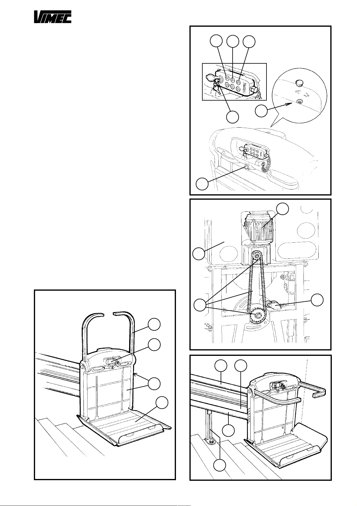
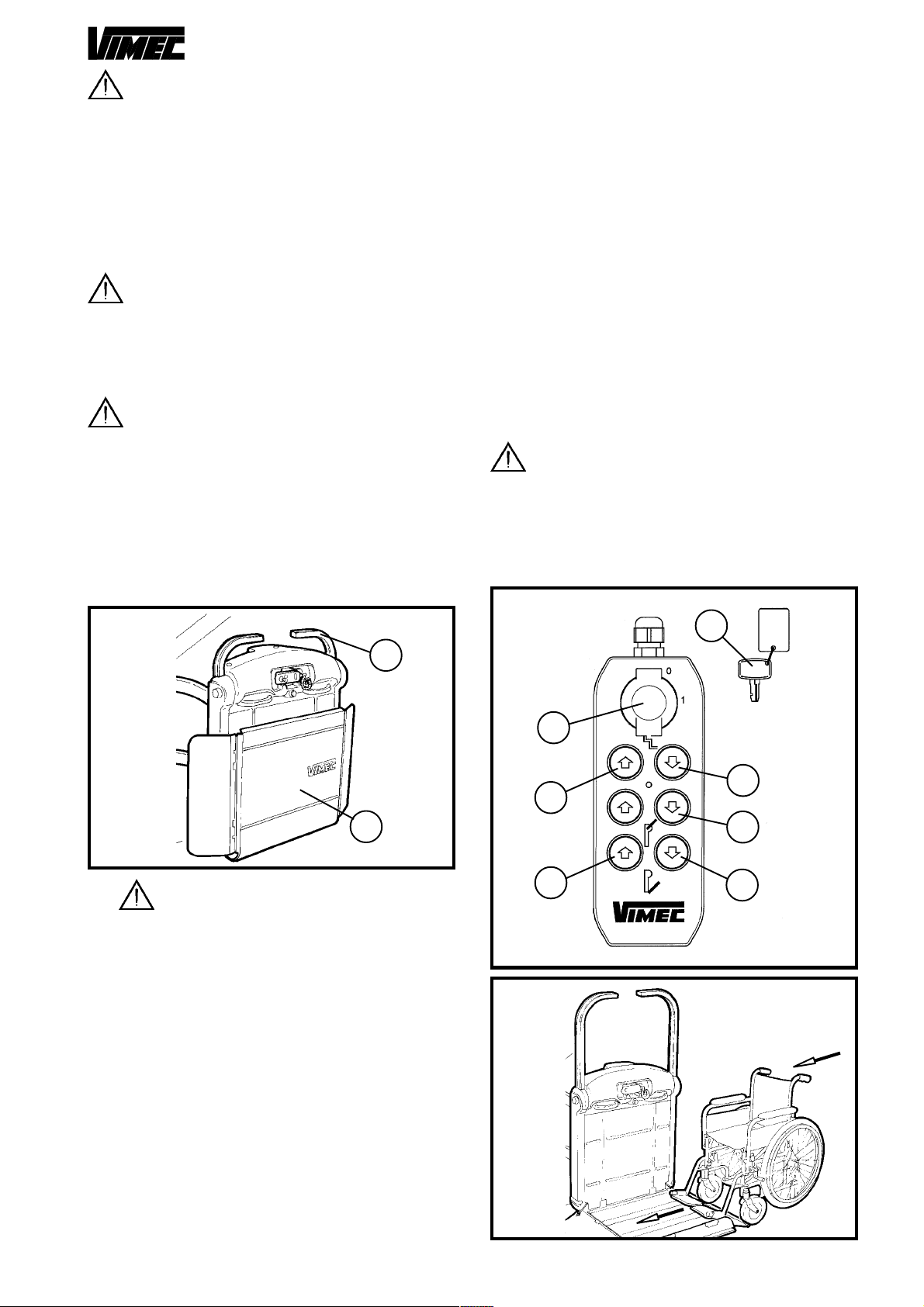
4) Press the up button (Fig. 9/c); the guards and bars
automatically move to the safety position and the lift
sets off.
5) B.C. Version. At the destination floor, the lift stops; if
the up button is kept pressed, the bars and the guard
facing in the up direction automatically move to the drive-
off position. The guard facing in the down direction is
locked in the safety position, to ensure the wheelchair
can leave and return to the lift in safety.
5) B.R. - B.I. Version. At the destination floor, the lift
stops; if the up button is kept pressed, the bars and the
guard facing in the up direction automatically move to
the drive-off position. The guard facing in the down di-
rection is locked in the safety position, to ensure the
wheelchair can leave and return to the lift in safety.
6) When the down button (Fig. 9/d) is pressed, the bars
and guard facing in the up direction move to the safety
position and the lift sets off.
7) At the destination floor, the lift stops; if the down but-
ton (Fig. 9/d) is kept pressed, the bars and the guards
automatically move to the drive-off position.
8) Return the lift to its initial condition (with platform
folded up and bars in rest position) (Fig. 8), turn the key
off and remove it.
N.B.: The bars and guards are mechanically locked in
position as long as the lift is travelling between the floors.
CAUTION: Pressing two buttons simulta-
neously, whether on the board on the lift or the
board at the floor, is strictly prohibited.
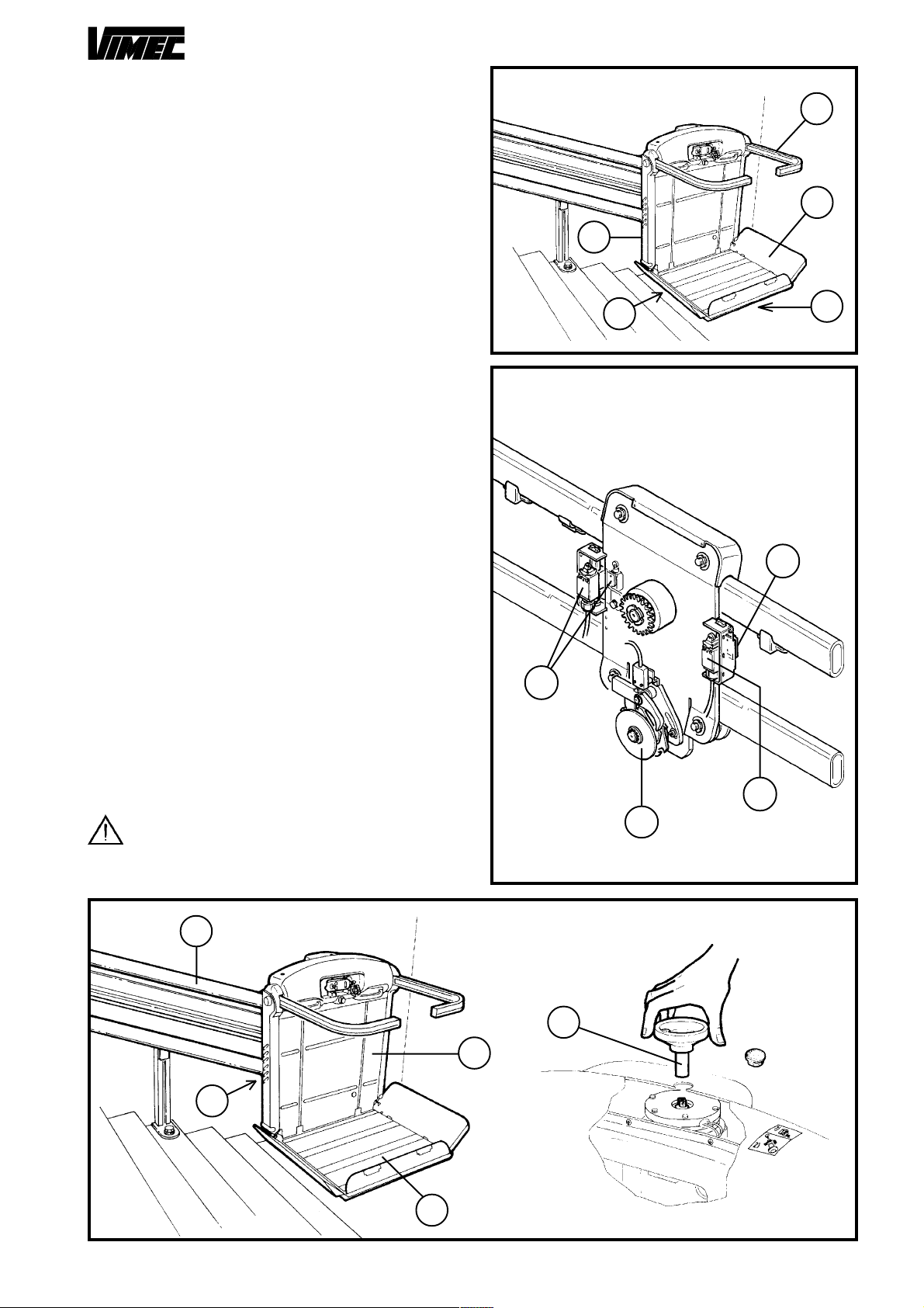
CAUTION: The person transported must al-
ways remain in the recommended position, with the
wheelchair brakes on, if the wheelchair is electric,
turn it off, as long as transport is in progress. The
feet must be kept on the wheelchair foot-rest and
the free hand on one of the platform handles (Fig.
11/c).
CAUTION: The person transported must al-
ways look in the travel direction and must stop the
stairlift immediately if there is anyone on the travel
route.
CAUTION: During operation of the stairlift the
landings and travel route must always be illumi-
nated (minimum 50 Lux measured at floor level).
CAUTION: Use of the stairlift by unauthorised
persons is not permitted. The key which enables
use of the stairlift must always be kept in a safe
place and access to it may only be permitted to
authorised persons.The key must always be re-
moved at the end of each trip.Leaving the key al-
ways in place is not permitted.
CAUTION: Never leave the platform halfway
up the staircase.
CAUTION: Never use the stairlift unless a
trained person is available to operate it in manual
mode in an emergency.
CAUTION: Never place your hands or any ob-
jects close to the rails or platform while the lift is in
motion.
CAUTION: If the machine is installed outside,
cover it with a protection cloth after using it.
Remove the keys from the push-button panel and
close the rubber lid (Fig. 9/a).
Note for motor-operated platform
The device makes it possible to upset the platform by
an actuator. The platform may be opened and closed
by special buttons panels located on the equipment and
(when required) on the floors (Fig. 9/b).
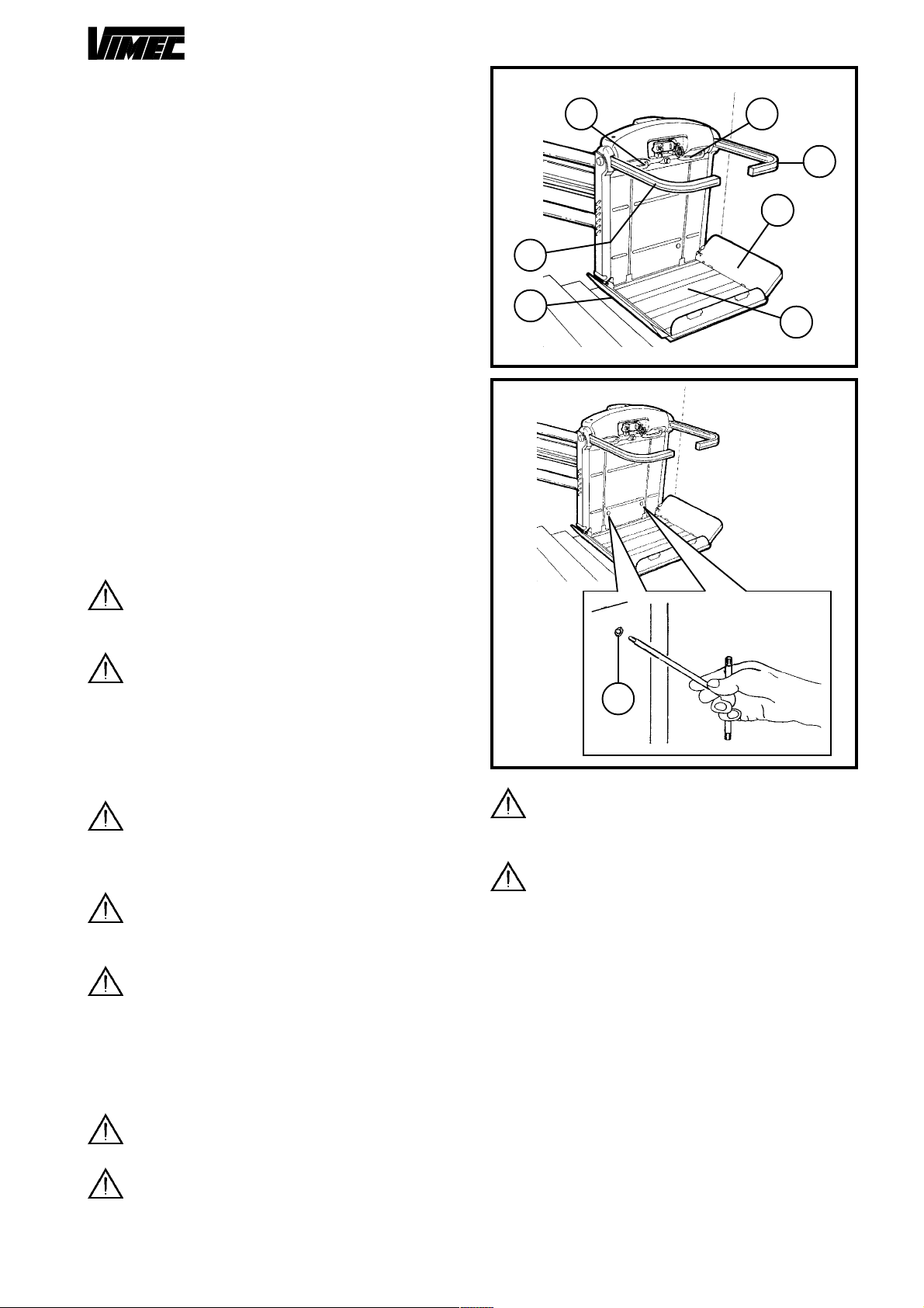
A special manual device makes it possible to close the
platform in case of emergency:
1) Push the release button (located on the front body
towards the descent side) (Fig. 12/c) paying attention
to make a light pression on the platform to avoid a sud-
denly shutting.
2) Pull the platform to gently, until the complete shut-
ting.
3) Reset the normal functions of the equipment after
the emergency by a manual complete opening of the
platform.
a
b
c
FIG.11
a
c
d
b
FIG.12
a