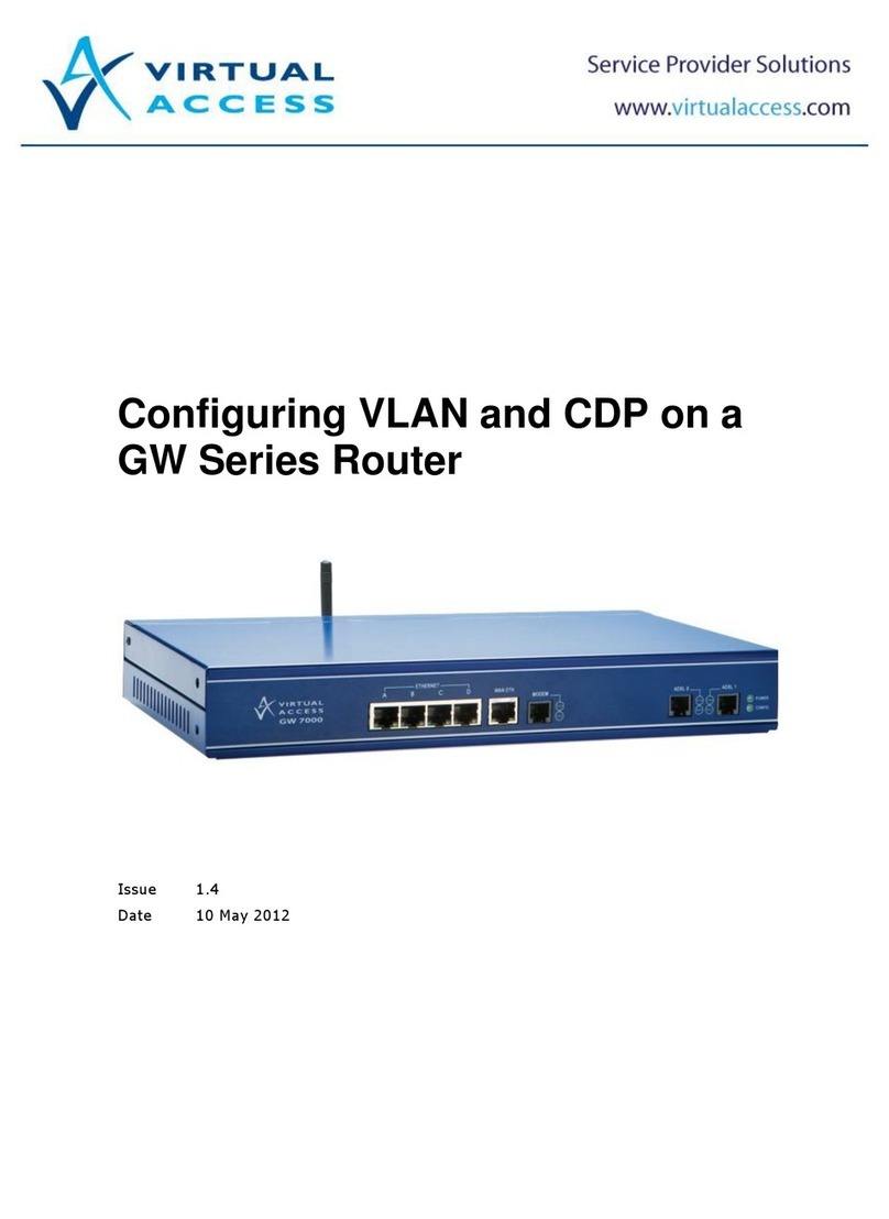
virtual access GW7000 Series Instruction Manual

Installing a GW7000 Series Router
Issue
1.3
Date
29 May 2013

Table of contents
1Location variants..................................................................................... 3
2Installing a GW7000 Series router in the UK ........................................... 4
2.1 Package contents for the UK .................................................................. 4
2.2 GW7000 Series serial and model descriptions for the UK ....................... 5
2.3 GW7000 series model descriptions ........................................................ 5
3Installing a GW7000 Series router in the UK before it is automatically
configured ............................................................................................... 7
3.1 Installing a GW7000 ADSL router in the UK ........................................... 7
3.2 Installing a GW7000 Series router with a serial connection in the UK.... 8
3.3 Installing a GW7000 Series router with an E1/T1 connection in the UK. 9
3.4 Installing a GW7000 3G connection in the UK ........................................ 9
3.5 Installing a GW7000 public Ethernet connection in the UK .................. 10
4Installing a GW7000 Series router outside the UK................................. 12
4.1 Package contents outside the UK ......................................................... 12
4.2 GW7000 Series serial and model descriptions outside the UK.............. 13
4.3 GW7000 series model descriptions ...................................................... 13
5Installing a GW7000 Series router outside the UK before it is
automatically configured....................................................................... 15
5.1 Installing a GW7000 ADSL router outside the UK................................. 15
5.2 Installing a GW7000 Series router with a serial connection outside the
UK ........................................................................................................ 16
5.3 Installing a GW7000 Series router with an E1/T1 connection outside the
UK ........................................................................................................ 17
5.4 Installing a GW7000 3G connection outside the UK ............................. 17
5.5 Installing a GW7000 Series router public Ethernet connection outside
the UK .................................................................................................. 18
Copyright 2013 Virtual Access (Irl) Ltd. This material is protected by copyright. No part of this material may be reproduced,
distributed, or altered without the written consent of Virtual Access. All rights reserved. Third party trademarks are the property
of the third parties.
Installing a GW7000 Series Router
Issue 1.3 Page 2 of 19

1: Location variants
1Location variants
There are cable variations for the GW7000 Series router depending on whether you have
bought your router for use in the UK or outside the UK.
If you are a UK customer, read section 2, ‘Installing a GW7000 Series router in the UK’.
If you are a customer outside the UK, read section 4, ‘Installing a GW7000 Series router
outside the UK’.
Installing a GW7000 Series Router © Virtual Access Ltd.
Issue 1.3 Page 3 of 19

2: Installing a GW7000 Series router in the UK
2Installing a GW7000 Series router in the UK
2.1 Package contents for the UK
If you are a UK customer, check that you have all the components listed below.
Table 1: Components for installing your GW7000
1x GW7000 Series router
1x purple ADSL cable Both ends of the cable looks like
this (RJ11):
If your GW7000 Series router has
dual ADSL a second purple ADSL
cable is provided
Both ends of the cable looks like
this(RJ11):
1x yellow Ethernet cable. Both ends of the cable look like
this (RJ45):
1x Black dial modem cable for
PSTN.
One end of the cable looks like this
(RJ11):
The other end of the cable looks
like a standard BT telephone
connector.
If your GW7000 Series router has a
serial port, you need a serial cable.
We do not provide a serial cable
with the GW7000 Series
1x power cable
1x ADSL splitter
1 x antenna (for 3G models only.)
2 x rack mounts
Installing a GW7000 Series Router © Virtual Access Ltd.
Issue 1.3 Page 4 of 19

2: Installing a GW7000 Series router in the UK
2.2 GW7000 Series serial and model descriptions for the UK
When you receive your GW7000 package retain the outer packaging. The label containing
the model number, serial number (S/N) and part number (P/N) is located on the side of the
packaging box.
Each GW7000 is assigned a unique serial number. Record your device serial number on a
printed copy of your warranty or somewhere you can easily access it. You must reference
your unique serial number (S/N) when you contact your distributor or Virtual Access support
for installation and configuration confirmation or should you request service on the device.
Figure 1: The model number on the side of the packaging
Unpack the contents. There is a corresponding silver label located on the bottom of the
router.
If your GW7000 Series router has dual ADSL, a second purple ADSL cable is provided.
If your GW7000 Series router has a serial port, you need a serial cable. We do not provide a
serial cable with the GW7000 Series router with a serial port. You can buy a serial cable
from your distributor. Make sure that the serial cable that you buy complies with the
interface that you use.
2.3 GW7000 series model descriptions
In the table below, match your model number. Check that all the parts are in your package
before you install your router.
If there is a 'Y' in a field, you should have that part. If there is a 2 in a field, you should have
two parts. If there is an ‘O’ in a field, it is an optional part. If you are missing any parts,
please contact your distributor.
Installing a GW7000 Series Router © Virtual Access Ltd.
Issue 1.3 Page 5 of 19

2: Installing a GW7000 Series router in the UK
Model
Number Port
Description Power
Cable WAN
Connection
Cable
RJ11
(purple)
Modem
(PSTN)
Cable
BT-RJ11
(black)
Ethernet
Cable
(yellow)
ADSL
Filter
GW7010 Quad Ethernet,
WAN Ethernet
Y Y - Y -
GW7025 Quad Ethernet,
WAN Ethernet
Y Y Y Y -
GW7110 Quad Ethernet,
ADSL,
WAN Ethernet
Y Y - Y O
GW7125 Quad Ethernet,
ADSL,
WAN Ethernet,
Modem
Y Y Y Y O
GW7210 Quad Ethernet,
Dual ADSL,
WAN Ethernet
Y 2 - Y O
GW7225 Quad Ethernet,
Dual ADSL,
Modem
Y 2 Y Y O
Table 2: GW7000 series model numbers
Installing a GW7000 Series Router © Virtual Access Ltd.
Issue 1.3 Page 6 of 19

3: Installing a GW7000 Series router in the UK before it is automatically configured
3Installing a GW7000 Series router in the UK before it is
automatically configured
The GW7000 Series router is shipped in its factory default configuration for automatic
configuration. After you have powered up the router for the first time, the config LED
flashes to indicate that it is in a factory default configuration. The router automatically
downloads its firmware and configuration files either via the ADSL or V90 connection.
After connecting the cables, the automatic configuration process will take between 5 – 10
minutes. After the configuration is complete, the unit will reboot. After reboot the config
LED will be solid to indicate that the automatic configuration process has been
successful.
If this process is not successful, contact your support team.
3.1 Installing a GW7000 ADSL router in the UK
Figure 2: The cables you need for an ADSL connection
There are two different size WAN connectors: 1 small black RJ11 and 1(or 2) small purple
RJ11(s); and 1 larger yellow RJ45.
1. On a GW7000 Series router, connect one end of a yellow RJ45 Ethernet cable to the
Ethernet port marked A. Connect the other end into the LAN port of your PC or to a LAN
hub.
2. Connect the RJ11 end of the black cable to the port marked MODEM. Connect the other
end to a PSTN telephone socket.
3. To connect directly to an ADSL service, connect one end of the RJ11 connector on the
purple cable to the port marked ADSL-0. Connect the other end of the RJ11 connector to
the ADSL socket on the wall. This socket can be an RJ45 or an RJ11 port. The RJ11 will
fit into both.
If you are using a cable modem or ADSL modem and not a direct service connection, do not
connect the ADSL cable. Connect one end of an Ethernet cable to the port marked WAN ETH.
Connect the other end to the Ethernet port on your cable modem or ADSL modem.
4. If you are using dual ADSL, connect one end of the second purple cable to the port
marked ADSL-1. This cable has an RJ11 connector on both ends. Connect the other end
of the RJ11 connector to the ADSL socket on the wall. This socket can be an RJ45 or an
RJ11 port. The RJ11 will fit into both.
Installing a GW7000 Series Router © Virtual Access Ltd.
Issue 1.3 Page 7 of 19
3: Installing a GW7000 Series router in the UK before it is automatically configured
The GW7000 Series router is shipped in its factory default configuration for automatic
configuration. The config LED will be flashing to indicate that it is in a factory default
configuration. The router automatically downloads its firmware and configuration files
either via the ADSL or V.90 connection. This process will take between 5 – 10 minutes.
After the download is complete, the unit will reboot. After reboot the config LED will be
solid to indicate that the automatic configuration process has been successful.
If this process is not successful, contact your support team.
3.2 Installing a GW7000 Series router with a serial connection in the UK
Figure 3: The cables you need for a serial and power connection
1. If you are using a serial connection, connect the serial cable to the serial port on the
back of the router.
2. Connect the power supply connector to the power port on the back of the router.
The router initialises. The CONFIG LED flashes and all the LEDs temporarily light in
sequence. Then the router activates.
The activation process can take between 5 and 10 minutes. The CONFIG light flashes
throughout activation. When activation finishes, your router enters operational mode.
If the LEDs on your router are not correctly lit, check that:
the cables are attached correctly, and
your service has been enabled by your provider.
Installing a GW7000 Series Router © Virtual Access Ltd.
Issue 1.3 Page 8 of 19

3: Installing a GW7000 Series router in the UK before it is automatically configured
3.3 Installing a GW7000 Series router with an E1/T1 connection in the
UK
Figure 4: The cables you need for an E1/T1 and power connection
1. For a standard connection, connect one end of the E1/T1 cable to the E1/T1 port on the
back of the router and the other end of the cable to an E1/T1 switch.
2. For a back-to-back connection, connect one end of an E1/T1 cross over cable to the
E1/T1 port on the back of the router. Connect the other end of the cable into the E1/T1
port of another device.
3. Connect the power supply connector to the power port.
The router initialises. The CONFIG LED flashes and all the LEDs temporarily light in
sequence. Then the router activates.
The activation process can take between 5 and 10 minutes. The CONFIG light flashes
throughout activation. When activation finishes, your router enters operational mode.
If the LEDs on the router are not correctly lit, check that:
the cables are attached correctly, and
your service has been enabled by your provider.
3.4 Installing a GW7000 3G connection in the UK
WARNING
The SIM card MUST be inserted into the router before the unit is powered on.
Do not insert or remove the SIM card after the unit has been powered on.
1. Ensure the unit is powered off.
2. Hold the SIM card with the chip side facing down and the cut corner top left.
3. Gently push the SIM card into SIM slot 1 until it clicks in.
To remove the SIM card, gently push the SIM card. The card will click out.
Installing a GW7000 Series Router © Virtual Access Ltd.
Issue 1.3 Page 9 of 19

3: Installing a GW7000 Series router in the UK before it is automatically configured
Figure 5: The position of the SIM card
4. Attach the antenna to the GW7000 Series router.
5. Connect the power supply connector to the power port.
The router initialises. The CONFIG LED flashes, and all the LEDs temporarily light in
sequence. Then the router activates.
The activation process can take between 5 and 10 minutes. The CONFIG light flashes
throughout activation. When activation finishes, the router enters operational mode.
If the LEDs on the GW7000 Series router are not correctly lit, check that:
the cables are attached correctly, and
your service has been enabled by your provider.
3.5 Installing a GW7000 public Ethernet connection in the UK
Figure 6: The cables you need for a public Ethernet connection
1. On the GW7000 Series router, connect one end of a yellow RJ45 Ethernet cable to the
Ethernet port marked A. Connect the other end into the LAN port of your PC or to a LAN
hub.
2. Connect one end of the Ethernet cable supplied by your service provider to the port
marked WAN ETH on the router. The other end of the Ethernet cable will already be
connected to the switch or socket provided by your service provider.
3. Connect the RJ11 end of the black cable to the port marked MODEM. Connect the other
end to a PSTN telephone socket.
4. Connect the power supply connector to the power port on the back of the router.
The router initialises. The CONFIG LED flashes and all the LEDs temporarily light in
sequence. Then the router activates.
The activation process can take between 5 and 10 minutes. The CONFIG light flashes
throughout activation. When activation finishes, the router enters operational mode.
Installing a GW7000 Series Router © Virtual Access Ltd.
Issue 1.3 Page 10 of 19

3: Installing a GW7000 Series router in the UK before it is automatically configured
If the LEDs on the router are not correctly lit, check that:
the cables are attached correctly, and
your service has been enabled by your provider.
Installing a GW7000 Series Router © Virtual Access Ltd.
Issue 1.3 Page 11 of 19

4: Installing a GW7000 Series router outside the UK
4Installing a GW7000 Series router outside the UK
4.1 Package contents outside the UK
If you are a customer outside the UK, check that you have all the components listed below.
Table 3: Components for installing your GW7000
1x GW7000 Series router
1x purple ADSL cable Both ends of the cable looks like
this:
1x purple dial modem cable for
PSTN Both ends of the cable looks like
this:
1x yellow Ethernet cable. Both ends of the cable look like
this:
If your GW7000 Series router has
dual ADSL a third purple ADSL
cable is provided.
Both ends of the cable look like
this:
If your GW7000 Series router has a
serial port, you need a serial cable.
We do not provide a serial cable
with the GW7000 Series.
1x regional power cable
1x ADSL splitter
1 x antenna (for 3G models only.)
2 x wall hinges
Installing a GW7000 Series Router © Virtual Access Ltd.
Issue 1.3 Page 12 of 19

4: Installing a GW7000 Series router outside the UK
4.2 GW7000 Series serial and model descriptions outside the UK
When you receive your GW7000 package retain the outer packaging. The label containing
the model number, serial number (S/N) and part number (P/N) is located on the side of the
packaging box.
Each GW7000 is assigned a unique serial number. Record your device serial number on a
printed copy of your warranty or somewhere you can easily access it. You must reference
your unique serial number (S/N) when you contact your distributor or Virtual Access support
for installation and configuration confirmation or should you request service on the device.
Figure 7: The model number on the side of the packaging
Unpack the contents. There is a corresponding silver label located on the bottom of the
router.
If your GW7000 Series router has dual ADSL, a second purple ADSL cable is provided.
If your GW7000 Series router has a serial port, you need a serial cable. We do not provide a
serial cable with the GW7000 Series router with a serial port. You can buy a serial cable
from your distributor. Make sure that the serial cable that you buy complies with the
interface that you use.
4.3 GW7000 series model descriptions
In the table below, match your model number. Check that all the parts are in your package
before you install your router.
If there is a 'Y' in a field, you should have that part. If there is a 2 in a field, you should have
two parts. If there is an ‘O’ in a field, it is an optional part. If you are missing any parts,
please contact your distributor.
Installing a GW7000 Series Router © Virtual Access Ltd.
Issue 1.3 Page 13 of 19

4: Installing a GW7000 Series router outside the UK
Model
Number Port
Description Power
Cable WAN
Connection
Cable
RJ11
(purple)
Modem
(PSTN)
Cable
BT-RJ11
(white)
Ethernet
Cable
(yellow)
ADSL
Filter
GW7010 Quad Ethernet,
WAN Ethernet
Y Y - Y -
GW7025 Quad Ethernet,
WAN Ethernet
Y Y Y Y -
GW7110 Quad Ethernet,
ADSL,
WAN Ethernet
Y Y - Y O
GW7125 Quad Ethernet,
ADSL,
WAN Ethernet,
Modem
Y Y Y Y O
GW7210 Quad Ethernet,
Dual ADSL,
WAN Ethernet
Y 2 - Y O
GW7225 Quad Ethernet,
Dual ADSL,
Modem
Y 2 Y Y O
Table 4: GW7000 series model numbers
Installing a GW7000 Series Router © Virtual Access Ltd.
Issue 1.3 Page 14 of 19

5: Installing a GW7000 Series router outside the UK before it is automatically configured
5Installing a GW7000 Series router outside the UK before it is
automatically configured
The GW7000 Series router is shipped in its factory default configuration for automatic
configuration. After you have powered up the router for the first time, the config LED
flashes to indicate that it is in a factory default configuration. The router automatically
downloads its firmware and configuration files either via the ADSL or V90 connection.
After connecting the cables, the automatic configuration process will take between 5 – 10
minutes. After the configuration is complete, the unit will reboot. After reboot the config
LED will be solid to indicate that the automatic configuration process has been
successful.
If this process is not successful, contact your support team.
5.1 Installing a GW7000 ADSL router outside the UK
Figure 8: The cables you need for an ADSL connection outside the UK
There are two different size WAN connectors: 2(or 3) small purple RJ11(s); and 1 larger
yellow RJ45.
1. On the GW7000 Series router, connect one end of the yellow RJ45 Ethernet cable to the
Ethernet port marked A. Connect the other end into the LAN port of your PC or to a LAN
hub.
2. Connect the RJ11 end of the purple cable to the port marked MODEM. Connect the other
end to the ADSL socket on the wall or to the splitter. This socket can be an RJ45 or an
RJ11 port. The RJ11 will fit into both.
3. To connect directly to an ADSL service, connect one end of the RJ11 connector on the
purple cable to the port marked ADSL-0. Connect the other end of the RJ11 connector to
the ADSL socket on the wall. This socket can be an RJ45 or an RJ11 port. The RJ11 will
fit into both.
If you are using a cable modem or ADSL modem and not a direct service connection, do not
connect the ADSL cable. Connect one end of the Ethernet cable to the port marked WAN
ETH. Connect the other end to the Ethernet port on your cable modem or ADSL modem.
4. If you are using dual ADSL, connect one end of the second purple cable to the port
marked ADSL-1. This cable has an RJ11 connector on both ends. Connect the other end
Installing a GW7000 Series Router © Virtual Access Ltd.
Issue 1.3 Page 15 of 19

5: Installing a GW7000 Series router outside the UK before it is automatically configured
of the RJ11 connector to the ADSL socket on the wall. This socket can be an RJ45 or an
RJ11 port. The RJ11 will fit into both.
The GW7000 Series router is shipped in its factory default configuration for automatic
configuration. The config LED will be flashing to indicate that it is in a factory default
configuration. The router automatically downloads its firmware and configuration files
either via the ADSL or V90 connection. This process will take between 5 – 10 minutes.
After the download is complete, the unit will reboot. After reboot the config LED will be
solid to indicate that the automatic configuration process has been successful.
If this process is not successful, contact your support team.
5.2 Installing a GW7000 Series router with a serial connection outside
the UK
Figure 9: The cables you need for a serial and power connection
1. If you are using a serial connection, connect the serial cable to the serial port on the
back of the router.
2. Connect the power supply connector to the power port on the back of the router.
The router initialises. The CONFIG LED flashes and all the LEDs temporarily light in
sequence. Then the router activates.
The activation process can take between 5 and 10 minutes. The CONFIG light flashes
throughout activation. When activation finishes, your router enters operational mode.
If the LEDs on the router are not correctly lit, check that:
the cables are attached correctly, and
your service has been enabled by your provider.
Installing a GW7000 Series Router © Virtual Access Ltd.
Issue 1.3 Page 16 of 19

5: Installing a GW7000 Series router outside the UK before it is automatically configured
5.3 Installing a GW7000 Series router with an E1/T1 connection outside
the UK
Figure 10: The cables you need for an E1/T1 and power connection
1. For a standard connection, connect one end of the E1/T1 cable to the E1/T1 port on the
back of the router and the other end of the cable to an E1/T1 switch.
2. For a back-to-back connection, connect one end of an E1/T1 cross over cable to the
E1/T1 port on the back of the router. Connect the other end of the cable into the E1/T1
port of another device.
3. Connect the power supply connector to the power port.
The router initialises. The CONFIG LED flashes and all the LEDs temporarily light in
sequence. Then the router activates.
The activation process can take between 5 and 10 minutes. The CONFIG light flashes
throughout activation. When activation finishes, your router enters operational mode.
If the LEDs on your router are not correctly lit, check that:
the cables are attached correctly, and
your service has been enabled by your provider.
5.4 Installing a GW7000 3G connection outside the UK
WARNING
The SIM card MUST be inserted into the router before the unit is powered on.
Do not insert or remove the SIM card after the unit has been powered on.
1. Ensure the unit is powered off.
2. Hold the SIM card with the chip side facing down and the cut corner top left.
3. Gently push the SIM card into SIM slot 1 until it clicks in.
To remove the SIM card, gently push the SIM card. The card will click out.
Installing a GW7000 Series Router © Virtual Access Ltd.
Issue 1.3 Page 17 of 19

5: Installing a GW7000 Series router outside the UK before it is automatically configured
Figure 11: The position of the SIM card
4. Attach the antenna to the GW7000 Series router.
5. Connect the power supply connector to the power port.
The router initialises. The CONFIG LED flashes, and all the LEDs temporarily light in
sequence. Then the router activates.
The activation process can take between 5 and 10 minutes. The CONFIG light flashes
throughout activation. When activation finishes, the router enters operational mode.
If the LEDs on the router are not correctly lit, check that:
the cables are attached correctly, and
your service has been enabled by your provider.
5.5 Installing a GW7000 Series router public Ethernet connection outside
the UK
Figure 12: The cables you need for a public Ethernet connection
1. On the GW7000 Series router, connect one end of a yellow RJ45 Ethernet cable to the
Ethernet port marked A. Connect the other end into the LAN port of your PC or to a LAN
hub.
2. Connect one end of the Ethernet cable supplied by your service provider to the port
marked WAN ETH on the router. The other end of the Ethernet cable will already be
connected to the switch or socket provided by your service provider.
3. Connect the RJ11 end of the black cable to the port marked MODEM. Connect the other
end to a PSTN telephone socket.
4. Connect the power supply connector to the power port on the back of the router.
The router initialises. The CONFIG LED flashes and all the LEDs temporarily light in
sequence. Then the router activates.
Installing a GW7000 Series Router © Virtual Access Ltd.
Issue 1.3 Page 18 of 19

5: Installing a GW7000 Series router outside the UK before it is automatically configured
The activation process can take between 5 and 10 minutes. The CONFIG light flashes
throughout activation. When activation finishes, the router enters operational mode.
If the LEDs on the router are not correctly lit, check that:
the cables are attached correctly, and
your service has been enabled by your provider.
Installing a GW7000 Series Router © Virtual Access Ltd.
Issue 1.3 Page 19 of 19
This manual suits for next models
13
Table of contents
Other virtual access Network Router manuals

virtual access
virtual access GW1000 Series User manual

virtual access
virtual access GW1000M User manual

virtual access
virtual access GW6600 User manual

virtual access
virtual access GW3330 User manual

virtual access
virtual access GW2040 Series User manual

virtual access
virtual access GW6610 User manual

virtual access
virtual access GW9000 Series Instruction Manual

virtual access
virtual access GW2040 Series User manual

virtual access
virtual access 6000 Series User manual

virtual access
virtual access GW1032 User manual