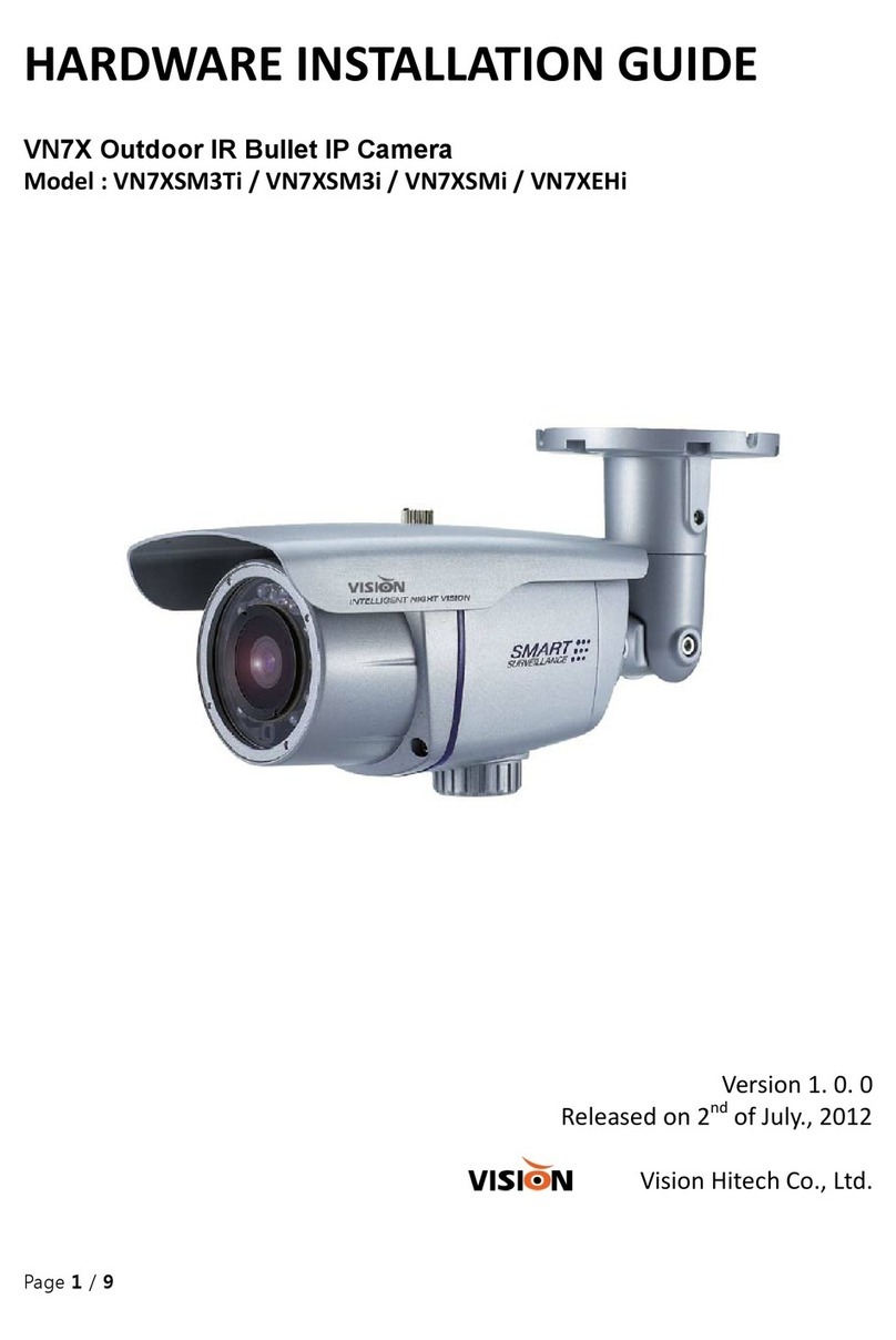
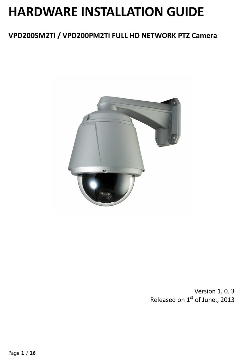
Vision VPD270 User manual

1
User’s Manual of Speed Domes
VPD270, VPD330WD & VPD370WD Series
Please read this manual carefully before installation and operation of the product.

2
Rev. 0_August 30, 201
Table of contents
1. Features -----------------------------------------------------------------------------
2. Precaution---------------------------------------------------------------------------
3. Part Names and Functions ----------------------------------------------
■ Body
■ Package
■ Camera cable connection
■ DIP Switch setting
■ Camera ID setting
■ RS-485 Comminication setting
4. Installation ------------------------------------------------------------------------
5. Functional description ----------------------------------------------------
■ Setup Menu Overview
■ Main Menu
1) PAN/TILT setting
2) Camera setting
3) Autoseq setting
4) Zone setting
5) Alarm setting
6) Initialize setting
7. Product Structure -----------------------------------------------------------
8. Specifications -----------------------------------------------------------------

3
1. Features
* Dynamic and precise AF control
The camera can trace and pick up the object, moving fast from the scene with powerful 324 times(Optical 27x, Digital
12x), 396 times(Optical 33x, Digital 12x), 444 times(Optical 37x, Digital 12x) zoom by greatly improved Auto Focus
control.
* Removable Motorized IR Cut Filter(ICR)
* Viewable at total darkness
The image at daytime displays as True Color with IR Cut filter attached and turns to
Clear B/W(color signal removed) mode at night(True Day/Night). With ICR, it comes to IR sensitive and enables the
camera to view the scene at total darkness.
*Super Wide Dynamic(sWDR)
With new powerful DSP system integrated, it makes more 126 times upgraded Backlight compensation than
that of existing BLC system
* High resolution of 550TVL(Color)/ 680TVL(Night)
* Powerful 27x/ 33x/ 37x optical zoom
* Extremely upgraded sensitivity of 0.7Lux(Sens-up off)/ 0.002Lux(Sens-up, 256x)/ 0.06Lux(B/W)
Clear difference with built –in Super DSP system and ICR mechanism is to surveil Objects clearly at even a starless
dark night. In addition the built –in Dynamic Noise Reduction(DNR) removes noises and ghost effect to have the
picture quality greatly improved.
It also saves the DVR’s recoding capacity up to 70%.
* Quick and Easy installation
Dome base is separated and easily mounted on the ceiling and the main body is simply hooked on it
by hand with no tool. No complicated cable connection is additionally required with the built-in one-stop
connection mechanism

4
2. Precaution
Safety Precautions
* The purpose of this information is to ensure proper use of this product to prevent danger to damage to property.
Please be sure to observe all precautions
* The precautions are divided into “Warnings” and “Cautions” as distinguished below;
Warning : Ignoring these warnings may result in death or serious injury.
Caution : Ignoring these cautions may result in injury or damage to property.
Warning :instructions alert you to
the potential risk of death
or serious injury
Caution : instructions alert you to the
potential risk of injury or
damage to property
Warnings
1. Be sure to use only the standard adapter which is specified in the specification sheet.
Using any other adapters could cause fire, electrical shock, or damage to the product.
2. When connecting the power supply and signal wires, check the external connection terminal before connecting
them. Connect the alarm signal wires to the alarm terminals, the AC adaptor to the AC power input receptacle,
and the DC adapter to the DC power Input, making sure that the correct polarity is observed.
(Connecting the power supply incorrectly may cause fire, electrical shock, or damage to the product.)
3. Do not connect multiple cameras to a single adapter.
(Exceeding the capacity may cause abnormal heat generation or fire.)
4. Securely plug the power cord into the power receptacle.
(Insecure connection may cause fire.)
5. When installing the camera on a wall or ceiling, fasten it securely and firmly.
(A falling camera may cause personal injury)
6. Do not place conductive objects(e.g. screwdrivers, coins, and metal things) or containers filled with water on top of
the camera.
(Doing so may cause personal injury due to fire, electrical shock or falling objects)

5
7. Do not install the unit in humid, dirty, or sooty locations
(Doing so may cause fire or electrical shock.)
8. If any unusual smell or smoke comes from the unit, stop using the product.
In such case, immediately disconnect the power source and contact the store of purchase.
(Continued use in such a condition may cause fire or electrical shock.)
9. If this product fails to operate normally, contact the store of purchase.
Never disassemble or modify this product in any way.
10. When cleaning, do not spray water directly onto parts of the product.
(Doing so may cause fire or electrical shock.)
Wipe the surface with a dry cloth. Never use detergents or chemical cleaners on the product, as this may result in
discoloration of surface or cause damage to the finish.
Cautions
1. Do not drop objects on the product or apply strong shock to it. Keep away from a location subject to excessive
vibration or magnetic interference.
2. Do not install in a location subject to high temperature(over 122℉), low temperature(below 14℉) or high humidity.
(Doing so may cause fire or electrical shock.)
3. Avoid a location which is exposed to direct sunlight or near heat sources such as heater or radiators.
(Neglecting to do so may result in a risk of fire.)
4. If you want to relocate the already installed product, be sure to turn off the power and then move or reinstall it.
5. Install in a well-ventilated location.
6. Remove the power plug from the outlet when there is a lightning storm.
(Neglecting to do so may cause fire or damage to the product.)

6
3) Part Names and Functions
■Body
Alarm In/out Cable
6
ALARM IN 4
RED
5
ALARM IN 3
SHIELD
4
GND
YELLOW
3
GND
BLUE
2
ALARM IN 2
BLACK
1
ALARM IN 1
WHITE
Camera Mounting Base
Video output
Power(24VAC)
Alarm Input
Relay output
RS-485 DATA
Safety Wire
Decorative Cover(provided)
Dome Anchor Ring
Dome Cover
Rotate the dome anchor ring to the left to remove it.
The dome cover is easily damaged
And should be handled with care
Lenz
Lens

7
Relay Output Cable
RS-485 Cable
■Package
6
N.C
5
COM2
YELLOW
4
OUT2
BLUE
3
COM1
BLACK
2
OUT1
WHITE
1
N.C
+
TRX+
-
TRX-

8

9
■Camera cable connection
■DIP SWITCH SETTINGS
In a configuration where the camera’s RS485 data port is used for Camera control(pan, tilt, etc.) by the system
controller, the camera’s DIP switches must be configured to specify the camera ID and communication parameters.
The camera mounting base needs to be removed to access the DIP switches.
See step 1 & 2 on page ? for the information about how to remove the camera mounting base.

10
■Camera ID setting
The factory default settings of these DIP switches are ID 1
(1-ON,0-OFF) SW1~SW8
DIP SW
ID
DIP SW
ID
DIP SW
ID
10000000
1
10101000
21
10010100
41
01000000
2
01101000
22
01010100
42
11000000
3
11101000
23
11010100
43
00100000
4
00011000
24
00110100
44
10100000
5
10011000
25
10110100
45
01100000
6
01011000
26
01110100
46
11100000
7
11011000
27
11110100
47
00010000
8
00111000
28
00001100
48
10010000
9
10111000
29
10001100
49
01010000
10
01111000
30
01001100
50
11010000
11
11111000
31
11001100
51
00110000
12
00000100
32
00101100
52
10110000
13
10000100
33
10101100
53
01110000
14
01000100
34
01101100
54
11110000
15
11000100
35
11101100
55
00001000
16
00100100
36
00011100
56
10001000
17
10100100
37
10011100
57
01001000
18
01100100
38
01011100
58
11001000
19
11100100
39
11011100
59
00101000
20
00010100
40
00111100
60
DIP SW
ID
DIP SW
ID
DIP SW
ID
10111100
61
11000110
99
10010001
137
01111100
62
00100110
100
01010001
138
11111100
63
10100110
101
11010001
139
00000010
64
01100110
102
00110001
140
10000010
65
11100110
103
10110001
141
01000010
66
00010110
104
01110001
142
11000010
67
10010110
105
11110001
143
00100010
68
01010110
106
00001001
144
10100010
69
11010110
107
10001001
145

11
01100010
70
00110110
108
01001001
146
11100010
71
10110110
109
11001001
147
00010010
72
01110110
110
00101001
148
10010010
73
11110110
111
10101001
149
01010010
74
00001110
112
01101001
150
11010010
75
10001110
113
11101001
151
00110010
76
01001110
114
00011001
152
10110010
77
11001110
115
10011001
153
01110010
78
00101110
116
01011001
154
11110010
79
10101110
117
11011001
155
00001010
80
01101110
118
00111001
156
10001010
81
11101110
119
10111001
157
01001010
82
00011110
120
01111001
158
11001010
83
10011110
121
11111001
159
00101010
84
01011110
122
00000101
160
10101010
85
11011110
123
10000101
161
01101010
86
00111110
124
01000101
162
11101010
87
10111110
125
11000101
163
00011010
88
01111110
126
00100101
164
10011010
89
11111110
127
10100101
165
01011010
90
00000001
128
01100101
166
11011010
91
10000001
129
11100101
167
00111010
92
01000001
130
00010101
168
10111010
93
11000001
131
10010101
169
01111010
94
00100001
132
01010101
170
11111010
95
10100001
133
11010101
171
00000110
96
01100001
134
00110101
172
10000110
97
11100001
135
10110101
173
01000110
98
00010001
136
01110101
174
DIP SW
ID
DIP SW
ID
DIP SW
ID
11110101
175
01010011
202
10100111
229
00001101
176
11010011
203
01100111
230
10001101
177
00110011
204
11100111
231
01001101
178
10110011
205
00010111
232
11001101
179
01110011
206
10010111
233
00101101
180
11110011
207
01010111
234
10101101
181
00001011
208
11010111
235

12
01101101
182
10001011
209
00110111
236
11101101
183
01001011
210
10110111
237
00011101
184
11001011
211
01110111
238
10011101
185
00101011
212
11110111
239
01011101
186
10101011
213
00001111
240
11011101
187
01101011
214
10001111
241
00111101
188
11101011
215
01001111
242
10111101
189
00011011
216
11001111
243
01111101
190
10011011
217
00101111
244
11111101
191
01011011
218
10101111
245
00000011
192
11011011
219
01101111
246
10000011
193
00111011
220
11101111
247
01000011
194
10111011
221
00011111
248
11000011
195
01111011
222
10011111
249
00100011
196
11111011
223
01011111
250
10100011
197
00000111
224
11011111
251
01100011
198
10000111
225
00111111
252
11100011
199
01000111
226
10111111
253
00010011
200
11000111
227
01111111
254
10010011
201
00100111
228
11111111
255
■RS485 Communication setting
Configuring DIP Switch as shown below resets communication parameters from the factory default setting by using
SW9 and SW10
SW10
SW9
BUAD RATE
PROTOCAL
0
0
9600BPS
PELCO-D
0
1
4800BPS
PELCO-D
1
0
9600BPS
PELCO-P
1
1
4800BPS
PELCO-P
NOTE
Factory Default : 9600bps, PELCO-D

13
4. Installation
■Preparing the Camera and Decorative Cover for Side Cable Exit
The camera and decorative cover should be prepared as shown below when mounting the camera on a ceiling or wall
with its cables(power, video output, RS485, alarm in Relay out) exiting from the side.
The camera mounting base needs to be removed in order to prepare the camera.
See step 1 and 2 below for information about how to remove the camera mounting base.
* Prevent the dome cover from being scratched by placing it on a soft cloth while you are working.
Preparing the Decorative Cover
■Installing the Camera for Indoor
* Select an installation location that is strong enough to withstand the total weight of the camera.
Installing the camera at a location that is too week can cause it to fall.
* If you are using an optional bracket to install the camera, install the bracket in accordance with the instructions that
come with it
1. Remove the fixing screw(M3x6) that secures the camera to the mounting base and put the screw in a place where it
will not become lost.
Step 1
Cut it off with a razor knife
Fixing screw

14
2. Rotate the camera base unit in the direction indicated by the arrow and remove it.
Step 2
3. To install the camera mounting base to ceiling, attach a template and drill the holes.
If you are using the top cable exit configuration, drill the top cable exit part to a template.
Note
When you use the camera mount base without a template, you can mark the location of four mounting holes & drill the
holes.
After loosening the screw,
press upwards on the camera and
then remove it
Rotate
Pull the camera
Mounting base
Up to remove it
Mark here
Rotate

15
4. Affix the camera mounting base onto the ceiling.
Use screws(M4) at the locations you marked above to secure the mounting base to the ceiling.
5. Attach the safety wire for securing the camera to the mounting base.
Pull on the safety wire to make sure its ring is securely connected to the mounting base.
NOTE
The safety wire is designed to allow the camera to hang from it.
Do not apply force greater than the weight of the camera to the wire.
6. Install the camera onto the mounting base.
Aligning with the mounting base, press down on the camera as far as it will go and rotate in the direction
indicated by the arrow.
7. Use the fixing screw you removed in step 1 in order to secure the camera to the mounting base.
8. Check the installation
* Is the camera leveled and installed securely?
Screw Screws
(M4, available separately)
Safety
Wire ring
Safety Wire Ring

16
* Is the camera free to looseness?
* Does the fixed part of the camera remain in place when you try to rotate it?
9. Separate the two parts of the decorative cover(that comes with camera)
Press upwards on the decorative cover at the points marked ■(indicated by the arrows in the illustration below) to
unlock the two parts from each other.
When removing the decorative cover, the direction to press(←) is shown on the side of the decorative cover.
Caution
Pressing up on the wrong side of the decorative cover can damage it.
10. Put the two parts of the decorative cover on the left and right side of the camera and hook them together.
Align the hooks and press one piece indicated by the arrow in the illustration below into the other piece.
Camera
Back
Unlock
Press
Fix securely
Press
Rotate
Camera
Mounting Base
Camera
Back
Back
Unlock
Fix securely
Press
Press
Hold securely

17
11. In case that the cable exits on the ceiling, fix the decorative cover to the ceiling firmly.
In case that the cable exits to the side, align the cutout in the decorative cover with the cable and slide
the decorative cover up firmly against the ceiling.
■Installing the Camera for Outdoor
Features
* Aluminum body and Polycarbonate Dome Cover.
* IP66 rated water/dust resistant and remarkable durability.
* Built-in Fan, Heater & Temperature sensor.
Press
Side Cable Exit Configuration
Align
Hook
Back
Press
Press
Top Cable Exit Configuration
Align with cutout

18
* Quick and easy to install.
* Neat design suitable for interior/exterior decoration
Precautions
* Note that you need to read carefully all contents related to safety and application methods before application.
* Be sure to use the Safety Wire Ring.
* Fasten the bracket strong enough to support the camera weight(approx. 5.5Kgs)
* The locations for installing the housing should be strong enough to fully secure the accessories, and all installations
need to be carried out by experienced engineers.
* Do not use chemicals for cleaning the enclosure as it may damage the surface.
Installation overview
Hexagonal Wrench
4-M4x10 Screw
Wall mount bracket
Wall mount O-Ring
Outdoor Main Body
Indoor Camera
Outdoor Dome Cover
Installation
1. Make four holes on the wall using the template provided.

19
2. After removing the mounting fix screw(M3), rotate the camera mounting base clockwise to remove it.
3. Fix the camera mounting base to the inside of the outdoor main body with the four screws(M4x8)
4. Attach the wall mount bracket to the wall and run cables. Be sure to line up it with for holes in the wall.
5. After inserting an O-Ring to the outdoor main body, attach the main body to the wall mount bracket with four
screws(M4x10) by wrench.

20
6. After attaching the indoor camera to the camera mounting base, turn and fix it clockwise. And tighten the mounting
fix screw with screw driver.
7. Insert the M4 x 10 bolt screws to secure the outdoor dome cover to the outdoor main body.
Specification
Operating
Temperature
-40°C ~ +50°C
Humidity
0 to 90% RH
Power Source
AC24V/1A
Construction
Aluminum & PC Plastic
This manual suits for next models
2
Table of contents
Other Vision Security Camera manuals

Vision
Vision VDA100SII User manual

Vision
Vision VNV23C54AR User manual

Vision
Vision VN6XSFHD User manual

Vision
Vision VN101PN User manual

Vision
Vision VN6XSFHD User manual

Vision
Vision VPD200PM2Ti Manual

Vision
Vision VN7X Manual

Vision
Vision VD102SFHD User manual

Vision
Vision VD70PA-180 User manual

Vision
Vision VN7XFHD User manual
Popular Security Camera manuals by other brands

GeoVision
GeoVision GV-IPCam H.264 Series Hardware manual

Primetech
Primetech PXA30SHE Operation manual

EverFocus
EverFocus ECZ 330 Installation and operation

Mini Gadgets
Mini Gadgets CDRFLD user manual

dallmeier
dallmeier DOMERA DDZ4010 HS/HD Series Installation and configuration

Texas Instruments
Texas Instruments MC-780PIx user guide