P/N 3100345 ISSUE 2 PAGE 2
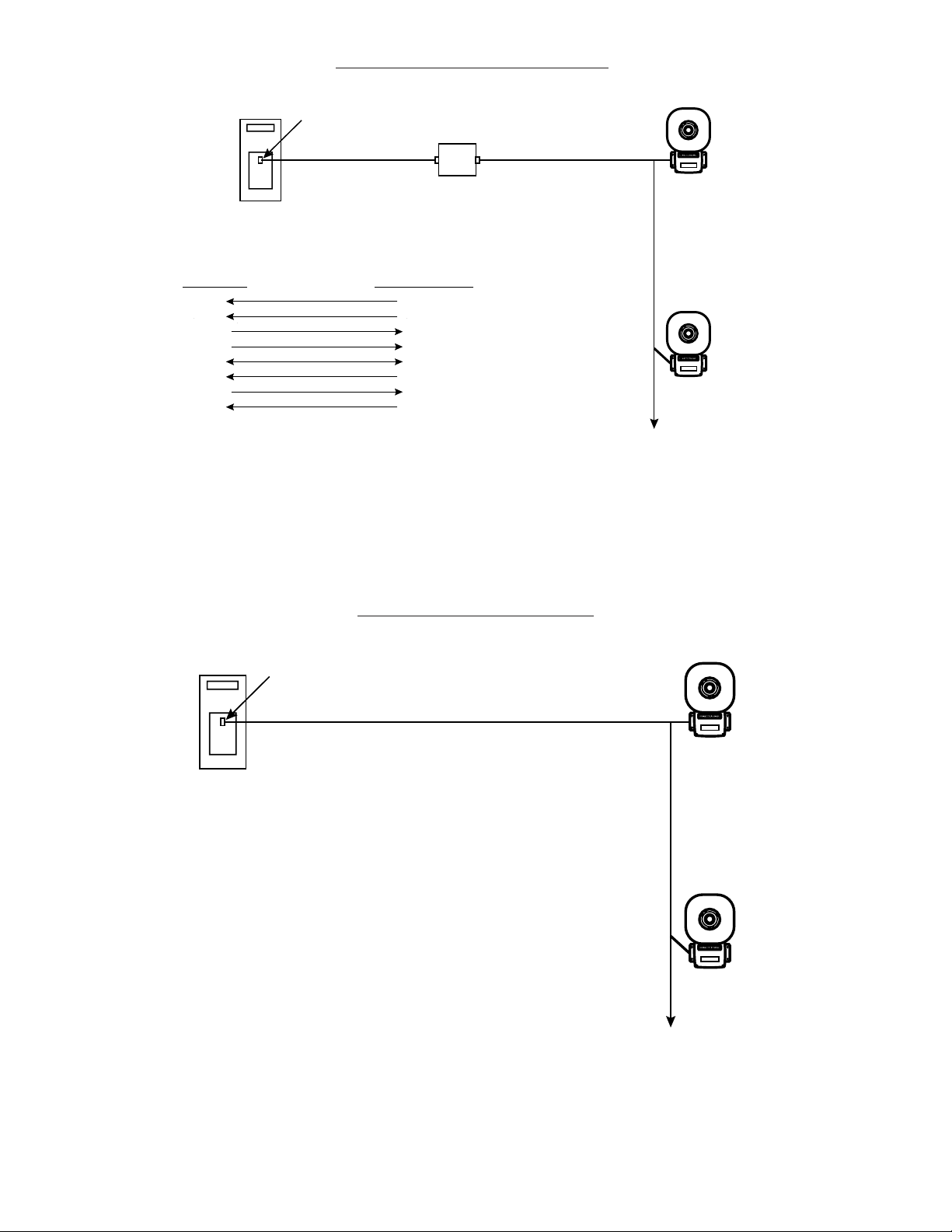
e. Optional. Connect external 24V DC battery (not
supplied) in series with separate diode assembly
part 2600010 (supplied) to TB1 terminals 3 and 4
on the main board as shown in Figures 3 and 4
and marked on the diode assembly.
NOTE: Terminal Block TB1 can be unplugged from the
main board to complete wiring as shown in
Figure 3.
NOTE: Cover screws are captive. Do not remove from
cover.
Removethe center knockoutin lower wallof box
and mount box to a 1/2" (12.7 mm) conduit pipe
using suitable connector.
2. Install wires through a knockout hole in the bottom
ofthe boxfrom araceway thatis, withitsconnections
tothe1/2"(12.7mm)conduitknockouthole,approved
forthe samedegree of protectionand enclosuretype
needed by the application. Use the provided plastic
tie-wrap,on thebarrier tothe electronics,to separate
incomingpower leads fromsignal andtone initiating
leads, per NEC (Figure 5).
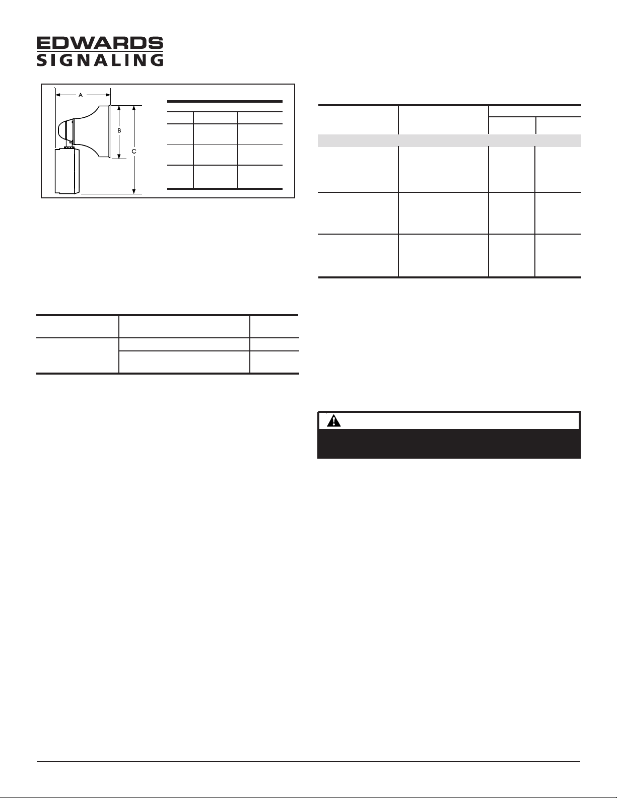
Figure 2. Adaptatone Mounting
WARNINGWARNING
WARNINGWARNING
WARNING
To prevent fire and shock, wire the Adaptatone only as
describedinthisinstallation instruction.
WARNINGSWARNINGS
WARNINGSWARNINGS
WARNINGS
HIGH VOLTAGE is present when product is energized. High
volume may cause harm to personnel in close proximity.
5. Adjust volume level, if desired, by turning
potentiometerlocated onthe mainboard (Figure11).
3. Wire as follows referring to Figures 5 and 6.
a. Connect green and yellow-striped earth-ground
wiresto earth-ground.
b. Connect theRS485 wires toterminals +TX/RXand
-TX/RX on the RS485 COMM board (Figure 6).
c. If using the optional MR201/C relay, connect the
relay to +RELAY and -RELAY on the RS485 COMM
board(Figure 6).
d. Connect incoming power to wire leads using a
butt splice or other method listed, certified, or
otherwise approved by local authorities. Leads
are black and white.
WARNINGWARNING
WARNINGWARNING
WARNING
To ensure integrity of the enclosure: Ensure the cover
gasket, part number P-007549-0069, is adhered into
groove at cover perimeter before replacing the signal box
cover.
Ensure that the (4) collar gaskets, part number P-041930-
0362, are in place on each cover screw before securing the
signalbox cover.
When securing cover, start screws by hand, making sure
they are threaded into tapped holes in housing bosses
before securing with a screwdriver. Torque signal box cover
screws to a minimum of 20 in-lbs. This ensures the
required tight fit.
6. Tightly secure the signal box cover using (4) retained
cover screws.
7. Torque signal box cover screws to a minimum of 20
in-lbs.
WARNINGWARNING
WARNINGWARNING
WARNING
To ensure integrity of the Adaptatone assembly when
adjusting the speaker direction, make sure threads in the
enclosure remain fully engaged and do not turn speaker
more than 360 degrees from the original factory installed
position.
WARNINGWARNING
WARNINGWARNING
WARNING
To ensure integrity of the Adaptatone assembly, prior to
completion of installation, make sure threads in the
enclosure are fully engaged and ensure that the star nut is
wrenchtight.
9. Regardless of speaker direction adjustment, it is
importantthat thestarnut betightened wrenchtight
toensure thespeaker position ismaintained securely.
10. Verify operability.
11. For tone selection and operation, refer to Figure 7
and the "Protocol" section of these installation
instructions.
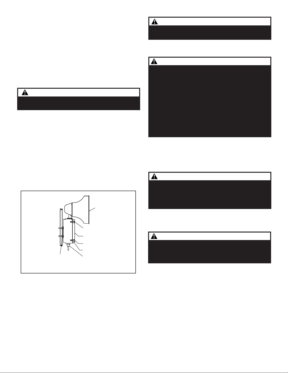
8. To adjust speaker direction, loosen large star nut
(Figure2)andturnspeakerto theapproximatedesired
position.
Speaker
Large star nut to
adjust speaker
direction
Signal Box
(4) Cover
screws
(4) Collar
gaskets
Raceway and connections
(not supplied) to
1/2" (12.7 mm) knockout
hole
(4) #10 x 3" (76 mm)
screws or other hardware
suitable for the mounting surface