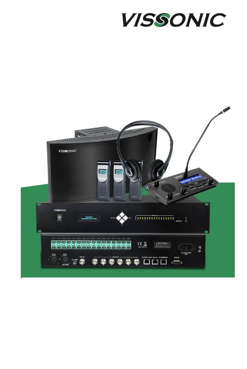
vissonic CLEACON User manual

CLEACON
Full Digital Network DSP Conference System
User Manual
V4.0
VISSONIC ELECTRONICS LIMITED

www.vissonic.com
1
The meaning of symbols
■ Safety instructions
For your safe and correct use of equipments, we use a lot of symbols on the equipments and in the
manuals, demonstrating the risk of body hurt or possible damage to property for the user or others.
Indications and their meanings are as follow. Please make sure to correctly understand these
instructions before reading the manual.
This isA level product, which may cause radio interference in the living
environment. In this case, users may need to take the feasible measures to
get around the interference.
Remind users that the dangerous voltage without insulation occurring
within the equipment may cause people suffer from shock.
CE certification means that the product has reached the directive safety
requirements defined by the European Union. Users can be assured about
the use of it.
SGS certification means that the product has reached the quality
inspection standards proposed by the world's largest SGS.
This product passed the ISO9001 international quality certification
(certification body: TUV Rheinland, Germany).
Warning: in order to avoid electrical shock, do not open the machine
cover, nor is the useless part allowed to be placed in the box. Please
contact the qualified service personnel.
■ General information instructions
It lists the factors leading to the unsuccessful operation or set and the
relevant information to pay attention.

www.vissonic.com
2
Important note
Warning
In order to ensure the reliable performance of the equipment and the safety of the user, please
observe the following matters during the process of installation, use and maintenance:
The matters needing attention of installation
Please do not use this product in the following places: the place of dust, soot and electric
conductivity dust, corrosive gas, combustible gas; the place exposed to high temperature,
condensation, wind and rain; the occasion of vibration and impact . Electric shock, fire,
wrong operation can lead to damage and deterioration to the product, either;
In processing the screw holes and wiring, make sure that metal scraps and wire head will not
fall into the shaft of controller, as it could cause a fire, fault, or incorrect operation;
When the installation work is over, it should be assured there is nothing on the ventilated
face, including packaging items like dust paper. Otherwise this may cause a fire, fault,
incorrect operation for the cooling is not free;
Should avoid wiring and inserting cable plug in charged state, otherwise it is easy to cause
the shock, or electrical damage;
The installation and wiring should be strong and reliable, contact undesirable may lead to
false action;
For a serious interference in applications, should choose shield cable as the high frequency
signal input or output cable, so as to improve the anti-jamming ability of the system.
Attention in the wiring
Only after cutting down all external power source, can install, wiring operation begin, or it
may cause electric shock or equipment damage;
This product grounds by the grounding wires .To avoid electric shocks, grounding wires and
the earth must be linked together. Before the connection of input or output terminal, please
make sure this product is correctly grounded;
Immediately remove all other things after the wiring installation. Please cover the terminals
of the products cover before electrification so as to avoid cause electric shock.
Matters needing attention during operation and maintenance
Please do not touch terminals in a current state, or it may cause a shock, incorrect operation;
Please do cleaning and terminal tighten work after turning off the power supply. These
operations can lead to electric shock in a current state;
Please do the connection or dismantle work of the communication signal cable , the
expansion module cable or control unit cable after turning off the power supply, or it may
cause damage to the equipment, incorrect operation;
Please do not dismantle the equipment, avoid damaging the internal electrical component;
Should be sure to read the manual, fully confirm the safety, only after that can do program
changes, commissioning, start and stop operation.

www.vissonic.com
3
Matters needing attention in discarding product
Electrolytic explosion: the burning of electrolytic capacitor on circuit boards may lead to
explosion;
Please collect and process according to the classification, do not put into life garbage;
Please process it as industrial waste, or according to the local environmental protection
regulations.

www.vissonic.com
4
Preface
This manual mainly describes the use, performance parameters and troubleshooting of VISSONIC
Full Digital Network DSP Conference System - including desktop, embedded, array unit and 5G
WiFi wireless conference system.
If the technical parameters and system usage in this manual are changed, the manufacturer will
update the version of the manual. Please use the latest user manual.
The copyright of the manual belongs to VISSONIC ELECTRONICS LIMITED. This manual is
protected by the Copyright Law of the People's Republic of China and other intellectual property
laws and regulations. Without permission, it is not allowed to copy part or all of the manual or
modify this manual.
Version
Update
Date
1.3
2.2 Extension Main Unit VIS-EXM 9
2.4 Connection Box 10
5.7 CONTROL 19
6.1.5 Camera Setup& Example 28
2017.1.18
1.3.1
6.1.2 Zone Setup 25
2017.2.6
1.3.2
5.3 Audio outputs 18
2017.2.7
1.3.3
6.1.5 Camera Setup& Example 28 (Change the flow diagram)
2017.3.11
1.3.4
Add WIFI model, flush model
2017.6.21
1.3.5
6.3 Configure the AP
7.5 Default setting
2017.6.27
1.3.6
Update manual forAP
2020.4.8
1.3.7
COM port definition connection
2020.7.17
1.3.9
Adding menu and POE
2022.4.22
3.3
Modifying and Adding menu& capacity
2023.4.10
4.0
New version released.
Adding:
VIS-DMD/MAU/MAW/DVCIC/DVDIC/WVCIC/WVDIC-T,
VIS-FFC/FFD-F1/F2, VIS-INT64, VIS-WCH2, POE speaker
ID, debug setting, Chapter 1 and 8.
Updating controller menu.
Modifying AP web page, audio zone and camera tracking, etc.
2023.7.26

www.vissonic.com
5
Contents
1. System overview...........................................................................................................................8
1.1 System features ...................................................................................................................8
1.2 System composition..........................................................................................................11
2. Conference controller..................................................................................................................13
2.1 VIS-DCP2000-D/W conference controller .......................................................................13
2.1.1 Features and interfaces...........................................................................................13
2.1.2 Installation..............................................................................................................15
2.1.3 Connection .............................................................................................................15
2.1.3.1 Connecting the power supply......................................................................15
2.1.3.2 Connecting audio inputs..............................................................................16
2.1.3.3 Connecting audio outputs............................................................................16
2.1.3.4 Connecting the conference controller..........................................................17
2.1.3.5 Connecting conference units.......................................................................17
2.1.3.6 Connecting an AP (only for VIS-DCP2000-W)..........................................18
2.1.3.7 Connecting for camera tracking..................................................................18
2.1.3.8 Connecting the PC software........................................................................20
2.1.4 Settings and usage..................................................................................................21
2.1.4.1 Menu and operations...................................................................................21
2.1.4.2 Setting MIC mode.......................................................................................28
2.1.4.3 Setting DSP.................................................................................................29
2.1.4.4 Setting audio zones......................................................................................31
2.1.4.5 Setting recording.........................................................................................34
2.1.4.6 Setting conference unit................................................................................35
2.1.4.7 Setting interpreter unit.................................................................................37
2.1.4.8 Setting camera tracking...............................................................................38
2.1.4.9 Setting network address ..............................................................................41
2.1.4.10 Setting POE speaker..................................................................................41
2.1.4.11 Setting system configuration.....................................................................43
2.1.4.12 Setting wireless communication (only for VIS-DCP2000-W)..................44
2.1.4.13 Setting debug configuration......................................................................44
2.1.4.14 Restoring to factory settings......................................................................45
3. Conference units .........................................................................................................................46
3.1 VIS-DCC/DCD/DVC/DVD/DVCIC/DVDIC/DIC/DID/DSC/DSD-T units ....................46
3.1.1 Features and interfaces...........................................................................................46
3.1.2 Connection .............................................................................................................50
3.1.3 Settings and usage..................................................................................................51
3.1.3.1 Setting unit ID.............................................................................................51
3.1.3.2 Setting unit types.........................................................................................52
3.1.3.3 Usage...........................................................................................................53
3.2 VIS-DMD-T unit...............................................................................................................55
3.2.1 Features and interfaces...........................................................................................55
3.2.2 Connection .............................................................................................................56

www.vissonic.com
6
3.2.3 Settings and usage..................................................................................................57
3.2.3.1 Setting unit ID.............................................................................................57
3.2.3.2 Setting unit types and rights........................................................................58
3.2.3.3 Usage...........................................................................................................58
3.3 VIS-MAU-T unit...............................................................................................................62
3.3.1 Features and interfaces...........................................................................................62
3.3.2 Connection .............................................................................................................63
3.3.3 Settings and usage..................................................................................................64
3.3.3.1 Setting unit ID.............................................................................................64
3.3.3.2 Setting unit types and rights........................................................................65
3.3.3.3 Usage...........................................................................................................65
3.4 VIS-ACC/ACD/DAC/DAD-T units..................................................................................68
3.4.1 Features and interfaces...........................................................................................68
3.4.2 Connection .............................................................................................................69
3.4.3 Settings and usage..................................................................................................69
3.5 VIS-DCC/DCD/CSU/DVU/SPK/FFC/FFD-F/FS/FS1/FS2/F1/F2 units ..........................70
3.5.1 Features and interfaces...........................................................................................70
3.5.2 Installation..............................................................................................................74
3.5.2.1 Hole sizes....................................................................................................74
3.5.2.2 Installation steps..........................................................................................75
3.5.3 Connection .............................................................................................................75
3.5.4 Settings and usage..................................................................................................76
3.6 VIS-WDC/WDD/WVC/WVD/WVCIC/WVDIC-T units.................................................77
3.6.1 Features and interfaces...........................................................................................77
3.6.2 Connection .............................................................................................................81
3.6.3 Settings and usage..................................................................................................82
3.7 VIS-MAW-T unit ..............................................................................................................83
3.7.1 Features and interfaces...........................................................................................83
3.7.2 Connection .............................................................................................................86
3.7.3 Settings and usage..................................................................................................86
3.7.3.1 Setting unit ID.............................................................................................86
3.7.3.2 Setting unit types and rights........................................................................87
3.7.3.3 Usage...........................................................................................................87
3.7.4 Web page of charger...............................................................................................91
3.7.4.1 Connection and login ..................................................................................91
3.7.4.2 Web-based management..............................................................................93
4. VIS-INT64 interpreter unit..........................................................................................................96
4.1 Features and interfaces......................................................................................................96
4.2 Connection........................................................................................................................97
4.2.1 Connected to controller..........................................................................................97
4.2.2 Connected to infrared transmitter...........................................................................98
4.3 Settings and usage.............................................................................................................99
4.3.1 Setting unit ID (only for connected to controller)..................................................99
4.3.2 Setting interpretation channel...............................................................................100
www.vissonic.com
7
4.3.3 Usage....................................................................................................................100
4.3.3.1 Setting operator.........................................................................................100
4.3.3.2 Screen contents..........................................................................................101
5. Extension devices......................................................................................................................103
5.1 VIS-EXM extension main unit........................................................................................103
5.2 VIS-CNB splitter box......................................................................................................103
5.3 VIS-HL network cable ....................................................................................................104
6. AP..............................................................................................................................................105
6.1 Features and interfaces....................................................................................................105
6.2 Installation.......................................................................................................................105
6.2.1 Installation diagram..............................................................................................105
6.2.2 Installation precautions ........................................................................................106
6.3 Connection......................................................................................................................107
6.4 Settings and usage...........................................................................................................107
6.4.1 Changing the AP channel.....................................................................................107
6.4.1.1 Connection ................................................................................................107
6.4.1.2 Configuration on Web page.......................................................................109
6.4.2 Changing the SSID and password........................................................................111
6.4.2.1 Changing the SSID and password of wireless conference system............111
6.4.2.2 Changing the SSID and password ofAP...................................................113
6.4.3 Restoring to factory settings.................................................................................114
7. System connection and use case ...............................................................................................116
7.1 System planning..............................................................................................................116
7.2 System connection ..........................................................................................................117
7.3 Use case...........................................................................................................................120
8. Technical specifications ............................................................................................................122
8.1 Camera tracking protocol................................................................................................122
8.2 Devices............................................................................................................................123
8.2.1 VIS-DCP2000-D..................................................................................................123
8.2.2 VIS-DCP2000-W.................................................................................................124
8.2.3 VIS-DCC/DCD/DVC/DVD/DVCIC/DVDIC/DIC/DID/DSC/DSD-T................125
8.2.4 VIS-DMD-T.........................................................................................................125
8.2.5 VIS-MAU-T.........................................................................................................126
8.2.6 VIS-DAC/DAD-T................................................................................................127
8.2.7 VIS-DCC/DCD/CSU/DVU/SPK/FFC/FFD-F/FS/FS1/FS2/F1/F2......................127
8.2.8 VIS-WDC/WDD/WVC/WVD/WVCIC/WVDIC-T ............................................128
8.2.9 VIS-MAW-T.........................................................................................................129
8.2.10 VIS-WBTY1......................................................................................................130
8.2.11 VIS-WCH1.........................................................................................................130
8.2.12 VIS-WBTY2/VIS-WBTY2-H............................................................................130
8.2.13 VIS-WCH2.........................................................................................................131
8.2.14 VIS-INT64 .........................................................................................................131
8.2.15 VIS-EXM/VIS-CNB/VIS-AP4C........................................................................132

www.vissonic.com
8
1. System overview
1.1 System features
CLEACON series of full digital network DSP conference system, based on VISSONIC’s self-
developed AUDIO-LINKTM voice distribution and processing technology, can offer the features of
discussion, voting, interpretation, sign-in, and control by computer software. The system supports
audio zoning, USB voice recording and monitoring, and camera tracking. With a high-
performance DSP processor that provides the audio processing algorithm, equalization technology.
In addition, the system supports hand in hand loop network and hot backup of the conference
controller.
The VISSONIC wireless conference system has all the features of the wired conference system
previously mentioned. Besides, the wireless system uses the standard 5G WiFi technology and the
WPA2-PSK (AES) encryption technology to provide a broader bandwidth with less interference,
higher security and confidentiality, and easier to install, use, transfer.

www.vissonic.com
9
Figure 1.1.1 Wired conference system

www.vissonic.com
10
Figure 1.1.2 Wireless conference system

www.vissonic.com
11
1.2 System composition
A basic VISSONIC wired conference system consists of a conference controller, conference units,
and CAT5e cables. An extension main unit VIS-EXM can be added for connecting more
conference units or increasing the communication distance. A splitter box VIS-CNB can be added
for connecting an array unit. A wireless conference system contains an additionalAccess Point
(AP) VIS-AP4C.
The conference controller, as the core in the conference system, controls all conference units
independently and supplies power to these units through POE. VISSONIC conference
management software can also be used on demand of more control and management features.
In the conference system, conference units are basic device used by attendees in a conference. The
features, permissions, and appearance vary with the model of the conference unit. For example,
the features include discussion, voting, interpretation, and sign-in. The unit provides permissions
for chairman, delegate, etc. The appearance varies with different installation modes, such as
desktop, array, or flush-mounting.
This manual is applicable to:
Full Digital Wireless DSP Conference Controller VIS-DCP2000-W
Full Digital Networked DSP Conference Controller VIS-DCP2000-D
CAT5 Wired Digital Discussion Chairman/Delegate Unit VIS-DCC-T/VIS-DCD-T
CAT5 Wired Digital Voting Chairman/Delegate Unit with Channel Selector VIS-DVC-
T/VIS-DVD-T
CAT5 Wired Digital Discussion+Voting IC Card Chairman/Delegate Unit with Channel
Selector VIS-DVCIC-T/VIS-DVDIC-T
CAT5 Wired Digital Interpreter Chairman/Delegate Unit VIS-DIC-T/VIS-DID-T
CAT5 Wired Dual Channels Chairman/Delegate Unit with Channel Selector VIS-DSC-
T/VIS-DSD-T
Multimedia Digital Conference Unit with Touch Screen VIS-DMD-T
Multimedia Wired Touch Screen Unit VIS-MAU-T
DigitalArray Microphone with Channels Selector Chairman/Delegate Unit VIS-ACC-T/VIS-
ACD-T
Digital Array Microphone Chairman/Delegate Unit VIS-DAC-T/VIS-DAD-T
CAT5 Digital Flush-mounting Discussion Chairman/Delegate Unit VIS-DCC-F/VIS-DCD-F
(all-round type) and VIS-DCC-FS/VIS-DCD-FS (economic type)
CAT5 Digital Flush-mounting 64 Channels Selector Unit VIS-CSU-F
CAT5 Digital Flush-mounting Voting Unit VIS-DVU-FS1 (with IC Card Reader) and VIS-
DVU-FS2
Flush-mounting Speaker Unit VIS-SPK-F
Flush-mounting All-in-one Discussion Chairman/Delegate Unit with Voting and Channel
Selector VIS-FFC-F1/VIS-FFD-F1 (simple type) and VIS-FFC-F2/VIS-FFD-F2 (big screen
type)

www.vissonic.com
12
Wireless Digital Discussion Chairman/Delegate Unit VIS-WDC-T/VIS-WDD-T
Wireless Digital Discussion+Voting Chairman/Delegate Unit VIS-WVC-T/VIS-WVD-T
Wireless Digital Discussion+Voting IC Card Chairman/Delegate Unit VIS-WVCIC-T/VIS-
WVDIC-T
5G Wireless Multimedia Conference Unit VIS-MAW-T
64 Channels Interpreter Desk VIS-INT64
Extension Main Unit VIS-EXM
Splitter Box VIS-CNB
2.4 GHz/5.0 GHz Conference Access Point VIS-AP4C

www.vissonic.com
13
2. Conference controller
2.1 VIS-DCP2000-D/W conference controller
2.1.1 Features and interfaces
VIS-DCP2000-D is a wired conference controller that supports wired Ethernet connection. This
controller controls all connected conference units and supplies power to these units through POE.
VIS-DCP2000-W is a wireless conference controller that supports 5G WiFi wireless connection
and wired Ethernet connection. This controller controls all connected conference units and
supplies power to wired conference units through POE.
Configure whole conference system with the buttons on the front panel of the conference
controller in the system.
Figure 2.1.1 VIS-DCP2000-D/W front and rear panels
Front panel:
No./Name
Description
1. Power Switch
Power on or off the controller.
2. Display
Show the current status or the result of operation, menu list etc.
3. Operate Buttons
4-direction buttons for menu operation, confirm and exit.
4. Audio Recording
Press to start/stop recording the audio of whole conference content.

www.vissonic.com
14
5. USB Slot
To insert USB disk (Up to 32G, FAT32) for recording, with status
light indicator which is flashing during the recording.
6. Headphone Socket
Headphone connection.
7. Knob
Control volume level of the system.
Rear panel:
Interface
Introduction
8. Audio Inputs (IN 1)
RCA audio input from external audio sources like MP3.
9. Audio Inputs (IN 2)
XLR audio input from external audio sources like Microphone and
remote audio input.
To use the AEC echo cancellation function of the controller, the
audio output of the video terminal must be connected to the IN2
input port.
10. Audio Outputs
(OUT 1)
RCA audio output to external audio devices like PA system,
loudspeakers etc. and can be set as zone 1 output.
11. Audio Outputs
(OUT 2)
XLR audio output to external audio devices like Mixer, PA system
etc. and can be set as zone 2 output.
12. Audio Outputs
(OUT 3, OUT 4,
OUT 5, OUT 6,
OUT 7, OUT 8)
Phoenix audio output. OUT3 and OUT4 can be set respectively as
zone 3 and zone4 output. OUT4 also can be set as echo cancellation
remote audio output. OUT5, OUT6, OUT7, OUT8 is corresponding
to the interpretation CH1, CH2, CH3, CH4.
OUT4 is used as audio output of the controller to the remote
terminal when the AEC acoustic echo cancellation function is used.
13. Audio Link
Extend to the next controller for conference room combination and
audio exchange.
14. CU/DU
It is used to connect chairman unit, delegate unit, interpreter unit or
POE speaker. Hand in hand loop connection can be made between
port 1 and port 2 or between port 2 and port 3.
15. AP (Only available
for VIS-DCP2000-W)
Connect to 2.4GHz / 5GHz Professional ConferenceAccess Point
VIS-AP4C.
16. Control
Female DP9 connector is used to connect with camera auto-tracking
controller.
17. Control
Male DP9 connector is used to connect with the camera chains or
third-party central controller.
18. Keyboard
Connect to the camera control keyboard.
19. Ethernet
Connect to PC or switch for the software control.
20. Ground jumper
Connect the controller to the ground.
21. Power inlet
Connect the controller to the main power supply with a power cable.
100-240VAC.

www.vissonic.com
15
2.1.2 Installation
The conference controller can be installed in a standard 19-inch cabinet. On both sides of the front
panel are standard screw holes for mounting the conference controller in the cabinet. The
installation diagram is as follows.
Figure 2.1.2 Mounting the conference controller
2.1.3 Connection
2.1.3.1 Connecting the power supply
Use the attached power cable to connect the conference controller to an external power socket.
Figure 2.1.3.1 Power interface of the conference controller

www.vissonic.com
16
2.1.3.2 Connecting audio inputs
The conference controller provides two types of audio input ports, RCAand XLR. The port
diagram and pin descriptions are as follows.
Figure 2.1.3.2Audio input ports
Type
Pin
Signal
Description
RCA
1
Live
Signal input
2
Return
Shield/ground
XLR
3
External
Shield/ground
4
Live
Positive
5
Return
Negative
2.1.3.3 Connecting audio outputs
The conference controller provides three types of audio output ports, RCA, XLR, and Phoenix.
The port diagram and pin descriptions are as follows.
Figure 2.1.3.3Audio output ports
Warning: The controller power supply needs to be well grounded to avoid accidents
that endanger personal safety.

www.vissonic.com
17
Type
Pin
Signal
Description
RCA
1
Live
Signal input
2
Return
Shield/Ground
XLR
3
External
Positive
4
Live
Shield/Ground
5
Return
Negative
Phoenix
6
+
Positive
7
-
Negative
8
G
Shield/Ground
2.1.3.4 Connecting the conference controller
The Audio Link ports of the conference controller are used for connecting other conference
controllers. Conference systems can be integrated by connecting their controllers with CAT5e
cable.
Figure 2.1.3.4Audio link ports
2.1.3.5 Connecting conference units
The CU/DU ports of the conference controller are used to connect conference units, VIS-CNB
splitter boxes, VIS-EXM extension main units, or POE speakers. VIS-CNB can be used to connect
more units. VIS-EXM can be connected to increase the capacity and transmission distance.
VISSONIC offers dedicated CAT5e cables for connection. You can also purchase qualified CAT5e
cables.

www.vissonic.com
18
Figure 2.1.3.5 CU/DU conference unit ports
2.1.3.6 Connecting anAP(only for VIS-DCP2000-W)
Figure 2.1.3.6 AP port
The AP port of wireless conference controller is used for connecting to VIS-AP4C 2.4 GHz/5.0
GHzAP. If multiple VIS-AP4C APs are used, connect theAP port of the conference controller to a
POE switch or a VIS-CNB splitter box, through which the controller connects to the VIS-AP4C
APs. Use a CAT5e cable for the connection.
2.1.3.7 Connecting for camera tracking
The CONTROL and KEYBOARD interfaces of the conference controller are used for the camera
tracking feature.
1. The CONTROL interface consists of two RS232 COM ports, as shown in the following
figure.
Note: It’s NOT recommended to connect other devices to the POE switch. It should connect
the controller VIS-DCP2000-W and up to 8 pieces of VIS-AP4C.

www.vissonic.com
19
Figure 2.1.3.7.1 CONTROL interface
The upper COM port is a female connector for connecting a VIS-CATC-A/B camera tracking
controller, which is used to switch channels during camera tracking. The following table lists
the default commands for channel switching. If want to customize the commands, contact us
for online firmware update.
Baud rate: 9600bps, parity: 8, Stop: 1.
Command
Description
1V1.
Switch the channel 1 to output
2V1.
Switch the channel 2 to output
3V1.
Switch the channel 3 to output
4V1.
Switch the channel 4 to output
…...
…...
14V1.
Switch the channel 14 to output
15V1.
Switch the channel 15 to output
16V1.
Switch the channel 16 to output
The lower COM port is a male connector for connecting a camera or a third-party central
controller.
The pin descriptions of the upper and lower COM ports are as follows:
Figure 2.1.3.7.2 Pin descriptions of the CONTROL interface
Pin description of the upper COM port (DB9 female/hole)
Pin
Signal
Description
1
-
Null
2
TXD
Transmit data
3
RXD
Receive data
4
-
Null
5
GND
Signal ground
Other manuals for CLEACON
2
Table of contents
Other vissonic Conference System manuals

vissonic
vissonic VIS-GSK-F User manual

vissonic
vissonic CLEACON User manual

vissonic
vissonic VLI Series User manual

vissonic
vissonic VIS-MAW-T User manual

vissonic
vissonic VLI Series User manual

vissonic
vissonic VIS-DMD-T User manual

vissonic
vissonic CLASSIC-D User manual

vissonic
vissonic CLASSIC-D User manual

vissonic
vissonic VIS-DMD-T User manual

vissonic
vissonic VIS-NP Series User manual