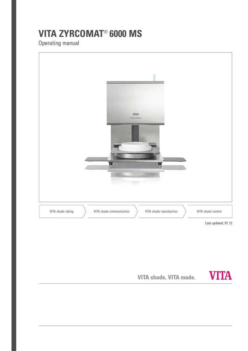
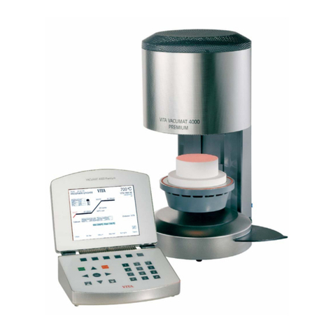
vita vacumat 40 User manual

VITA - Vacumat 40
Operating Manual

VITA - Vacumat 40
39/03/04 Vita Zahnfabrik H.Rauter GmbH&Co.KG 79704 Bad Säckingen 1
CONTENTS
1 Technical information.................................................................................................................... 3
1.1 General functions...................................................................................................................... 3
1.2 Technical data........................................................................................................................... 3
1.3 Electrical data............................................................................................................................ 3
1.4 Scope of delivery....................................................................................................................... 3
2 Installation and starting-up ........................................................................................................... 4
2.1 Installation ................................................................................................................................. 4
2.2 Connecting the furnace to the mains supply............................................................................. 4
2.3 Furnace out of operation........................................................................................................... 4
3 Safety advice................................................................................................................................... 5
3.1 Information of labels.................................................................................................................. 5
3.2 Cleaning of the furnace............................................................................................................. 5
3.3 Fuses......................................................................................................................................... 5
3.4 CE-mark.................................................................................................................................... 6
3.5 Cooling fan ................................................................................................................................ 6
4 Protection against power failure................................................................................................... 6
5 Rapid cooling down of the firing chamber .................................................................................. 6
6 Standby - Mode............................................................................................................................... 6
7 Firing programs.............................................................................................................................. 7
7.1 General information on firing programs and display ................................................................. 7
7.2 Temperature rising rate............................................................................................................. 8
7.3 Vacuum display......................................................................................................................... 8
7.4 Function of keys in the On -, Set - and Run - Mode.................................................................. 9
7.5 Set-Mode, selecting a program, changing program values..................................................... 10
7.6 Run-Mode, program started....................................................................................................11
7.7 Entering / changing / deleting vacuum parameters................................................................. 11
7.8 Slow cooling ............................................................................................................................ 12
8 Lift position for pre-drying .......................................................................................................... 13
9 Utilities........................................................................................................................................... 14
9.1 Functions of keys in the Service-Mode: .................................................................................. 14
9.2 Service No. 1 Standby ( Standby - Temperature) ................................................................. 14
9.3 Service No. 2 Lift speed ........................................................................................................ 15
9.4 Service No. 3 Signal time...................................................................................................... 15
9.5 Service No. 4 Function STOP - key ....................................................................................... 16
9.6 Service No. 5 Show total operating hours.............................................................................. 16
9.7 Service No. 6 Show total operating hours of muffle.............................................................. 16
9.8 Service No. 7 Call up furnace No........................................................................................... 17
9.9 Service No. 8 Call up software No. ....................................................................................... 17
9.10 Service No. 9 Service-Hotline ............................................................................................... 17
9.11 Service No. 10 Temperature adjustment with silver sample.................................................. 18

VITA - Vacumat 40
39/03/04 Vita Zahnfabrik H.Rauter GmbH&Co.KG 79704 Bad Säckingen 2
9.11.1 Silver sample set VITA - Order No. B 230...................................................................... 19
9.12 Service No. 11 Automatic temperature adjustment................................................................ 19
9.13 Service No. 12 Code digit for PC connection......................................................................... 20
9.14 Service No. 13 Activate/reactivate data transfer.................................................................... 20
9.15 Service No. 14 Brightness / contrast of display...................................................................... 20
9.16 Service No. 15 Setting of time................................................................................................ 21
9.17 Service No. 16 Time – Date format........................................................................................ 21
9.18 Service No. 17 Show – hide display messages ..................................................................... 22
9.19 Service No. 18 Enter furnace parameters.............................................................................. 22
9.20 Service No. 19 Read firing table in the memory:.................................................................... 23
9.21 Service No. 20 Delete process data....................................................................................... 24
9.22 Service No. 21 Firing program – write / read parameters ...................................................... 24
9.23 Service No. 22 Service – write / read parameters.................................................................. 25
9.24 Service No. 23 Language....................................................................................................... 25
9.25 Service No. 24 Hold –temperature- program ......................................................................... 26
10 Error messages Error 01 - Error 29............................................................................................. 27
11 Data transfer ................................................................................................................................. 28
11.1 Activate data storage............................................................................................................... 28
11.2 Connection to PC for data transfer..........................................................................................28
12 Firing Cycle Charts....................................................................................................................... 29

VITA - Vacumat 40
39/03/04 Vita Zahnfabrik H.Rauter GmbH&Co.KG 79704 Bad Säckingen 3
1 Technical information
1.1 General functions
•100 freely programmable firing programs
•Illuminated graphic display
•Clearly-structured and controllable firing cycles
•1 long-time cooling phase can be selected for each program
•Highest temperaturer accuracy
•Temperature adjustment program with silver sample
•Automatic temperature adjustment
•In case of power cut < 10 sec no abortion of program
•In case of power cut > 10 sec message in display
•Choice of three lift positions in pre-drying phase
1.2 Technical data
Dimensions: Width: 220 mm
Depth: 320 mm
Height: 420 mm
Casing: steel / stainless steel
Weight: 10.5 kg
Firing chamber - capacity: Diameter : 90 mm
Height: 55 mm
Firing chamber - temperature: max. 1200°C
1.3 Electrical data
Power supply: 230 Volts AC, 50 Hz
Power consumption: max. 1500 Watts
Classification: Safety class 1
Power supply for vacuum pump: 230 Volts, 50/60 Hz or 100/110 Volts, 50/60 Hz, max. 0.2 KW
1.4 Scope of delivery
Furnace in special shipping carton with:
•1 operating element
•1 firing tray
•1 mains power lead
•1 pair of furnace tweezers
•1 set of firing trays A + B
•1 set of firing trays G
•1 operating manual
vacuum pump (option) : 230 Volts, 50/60HZ
Weight approx. 6.4 kg

VITA - Vacumat 40
39/03/04 Vita Zahnfabrik H.Rauter GmbH&Co.KG 79704 Bad Säckingen 4
2 Installation and starting-up
2.1 Installation
•When positioning the furnace, the minimum distance of the furnace
and any wall is at least 25 cm.
•At temperatures of less than 15°C (e.g after transport) leave the
unit for approx. 30 min. before starting-up.
•Make sure that the unit is placed on a heat-resistant surface. Heat
radiation and heating up of the unit are within a harmless range.
However it can not be excluded, that sensitive furniture surfaces
and veneerings may exhibit slight discoloration due to continuous
exposure to heat.
•The unit must not be exposed to direct sunlight.
•Do not place any combustible objects near the furnace.
•Do not place operating element directly into the heat radiation area
of the firing chamber.
2.2 Connecting the furnace to the mains supply
Notice: Prior to starting-up, observe safety advice item 3!
•Connect furnace to the mains supply (fig. 1). Do not use multiway
socket outlet with extension, overload may result in a fire.
•Connect vacuum pump (fig. 1).
•Connect operating element with the furnace (on the side) and open
it (fig. 2). Do not place operating element in the area of direct heat
radiation of the firing chamber.
•Switch on the furnace with the main switch (fig. 1), lift will descend
into lower position.
•Place the firing tray onto the lift support plate. (fig. 2)
•Activate with Standby Mode key (for further information see
Standby Mode)
2.3 Furnace out of operation
If the furnace is not used, the lift should be moved with into the firing chamber and the unit should be
switched off with the main switch. Closing the firing chamber will protect the insulation and avoid the
absorption of moisture.
fig. 1
Firing object plate
Main switch
Vacuum connection
Connection
vacuum pump
110 / 115 volt or230 volt
Main connection
Fuses
fig. 2
Firing platform
Table of contents
Other vita Laboratory Equipment manuals
Popular Laboratory Equipment manuals by other brands

Belden
Belden HIRSCHMANN RPI-P1-4PoE installation manual

Koehler
Koehler K1223 Series Operation and instruction manual

Globe Scientific
Globe Scientific GCM-12 quick start guide

Getinge
Getinge 86 SERIES Technical manual

CORNING
CORNING Everon 6000 user manual

Biocomp
Biocomp GRADIENT MASTER 108 operating manual