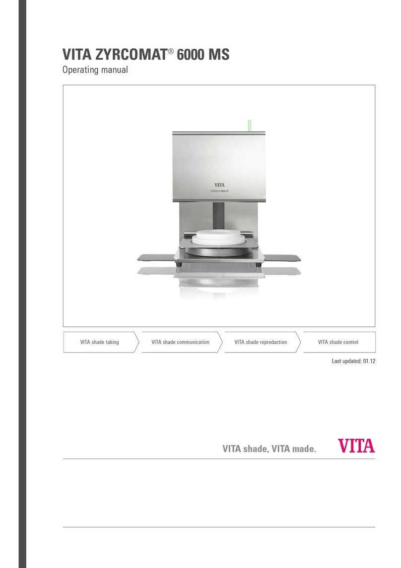
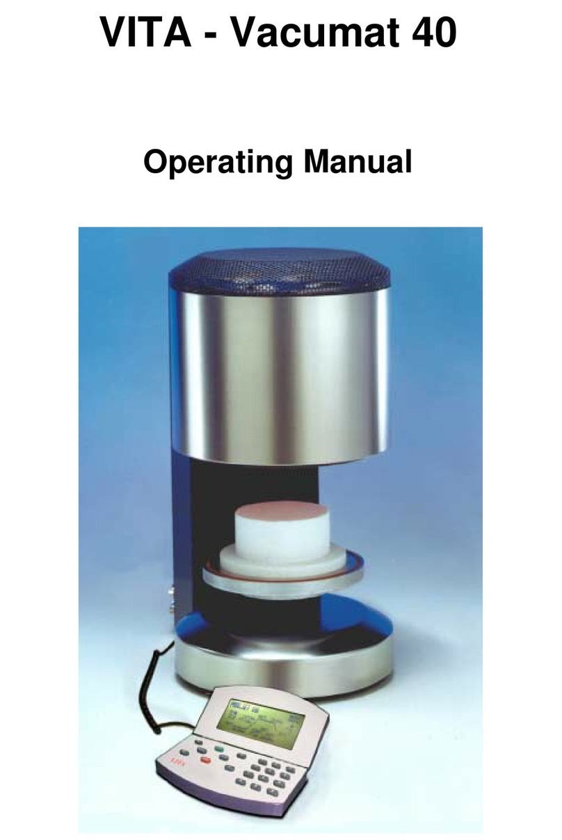
vita vacumat 4000 premium t User manual

VITA VACUMAT
4000
PREMIUM
T
Operating manual
Date of issue: 07-07
®

VITA Vacumat®4000 Premium T
3
Table of contents
1FOREWORD ...............................................................................................................................................6
1.1 PICTOGRAMS....................................................................................................................................6
1.2 COPYRIGHT ......................................................................................................................................6
2TECHNICAL INFORMATION .....................................................................................................................7
2.1 GENERAL DESCRIPTION .................................................................................................................7
2.2 EXTERNAL CONTROL EQUIPPED WITH.........................................................................................7
2.3 FIRING PROGRAMS..........................................................................................................................8
3SERVICE PROGRAMS...............................................................................................................................8
4SAVING OF FIRING DATA FOR QUALITY ASSURANCE........................................................................9
5SAFETY FUNCTIONS ................................................................................................................................9
6DIMENSIONS/WEIGHTS ..........................................................................................................................10
6.1 FIRING UNIT ....................................................................................................................................10
6.2 CONTROL UNIT...............................................................................................................................10
6.3 ELECTRIC DATA FIRING UNIT/CONTROL UNIT ...........................................................................10
6.4 ELECTRIC DATA VACUUM PUMP..................................................................................................10
6.5 SCOPE OF DELIVERY.....................................................................................................................10
7INSTALLATION AND START-UP ............................................................................................................11
7.1 MOUNTING LOCATION ...................................................................................................................11
7.2 CONNECTING THE UNIT TO THE MAINS SUPPLY.......................................................................12
7.3 SHUTTING DOWN THE UNIT, OUT OF OPERATION ....................................................................13
8NOTES ON SAFETY.................................................................................................................................13
8.1 INTENDED USE ...............................................................................................................................13
8.2 NOTES ON INFORMATION DECALS..............................................................................................14
8.3 CLEANING THE FIRING UNIT.........................................................................................................15
8.4 OPERATION AND CLEANING OF THE CONTROL UNIT...............................................................15
8.5 FUSES..............................................................................................................................................15
8.6 CE – SIGN ........................................................................................................................................15
8.7 FAN...................................................................................................................................................16
8.8 VOLTAGE SUPPLY FAILURE..........................................................................................................16
8.9 WARRANTY AND LIABILITY ...........................................................................................................16
8.10 SPARE PARTS.................................................................................................................................16
9TEMPERATURE RISE..............................................................................................................................17
10 AUTOMATIC TEMPERATURE ADJUSTMENT. ......................................................................................17
11 USER ASSIGNED PROGRAMS...............................................................................................................18
11.1 CHANGING THE USER/CREATING A USER .................................................................................18
12 GENERAL OPERATION OF UNIT ...........................................................................................................19
12.1 NUMERICAL INPUT.........................................................................................................................19
12.2 ALPHANUMERICAL/NUMERICAL INPUT .......................................................................................20

VITA Vacumat®4000 Premium T
4
12.3 QUICKSTARTING A FIRING PROGRAM – QUICKSTART ............................................................20
13 START MENU ...........................................................................................................................................21
14 STANDBY .................................................................................................................................................22
14.1 ADJUSTMENT OF STANDBY TEMPERATURE..............................................................................22
14.2 START/STOP STANDBY MODE......................................................................................................23
15 SELECTING A FIRING PROGRAM..........................................................................................................24
16 CHANGING PROGRAM VALUES............................................................................................................26
16.1 CHANGING PROGRAM VALUES IN GRAPHICS MODE................................................................26
16.2 CHANGING PROGRAM VALUES IN TABULAR MODE ..................................................................28
17 LIFT POSITIONS AND POSITION TIMES FOR PRE-DRYING................................................................30
17.1 DIRECT INPUT OF CHANGES FOR LIFT POSITION AND POSITION TIME.................................31
17.2 INPUT OF CHANGES TO LIFT POSITION AND POSITION TIME IN THE PRE-DRYING MENU . 33
18 LIFT POSITIONS FOR COOLING ............................................................................................................34
18.1 DIRECT INPUT OF CHANGES TO THE LIFT POSITION COOLING ..............................................34
18.2 ENTERING CHANGES TO THE LIFT POSITION IN THE COOL DOWN MENU ............................35
19 VACUUM SETTINGS................................................................................................................................37
20 PRE-VACUUM ADJUSTMENT.................................................................................................................39
21 CREATING PROGRAM GROUPS............................................................................................................39
21.1 DELETING PROGRAM GROUPS. ...................................................................................................41
21.2 CHANGING A PROGRAM GROUP..................................................................................................42
21.3 COPYING/INSERTING A PROGRAM GROUP................................................................................44
21.4 SORTING PROGRAM GROUPS......................................................................................................45
22 CREATING NEW FIRING PROGRAMS ...................................................................................................47
22.1 DELETING FIRING PROGRAMS .....................................................................................................49
22.2 CHANGING FIRING PROGRAMS....................................................................................................51
22.3 COPYING/INSERTING FIRING PROGRAMS..................................................................................53
23 SERVICE PROGRAMS.............................................................................................................................56
23.1 INFORMATION ABOUT THE UNIT/SOFTWARE.............................................................................56
23.2 LANGUAGE SELECTION.................................................................................................................56
23.3 EXPORT FAILURE REPORT ...........................................................................................................57
23.4 SCREEN SETTINGS ........................................................................................................................57
23.5 PROCESS DATA..............................................................................................................................57
23.6 LOADING FIRING PROGRAMS FROM THE MEMORY STICK ......................................................57
23.7 DATE/TIME.......................................................................................................................................58
23.8 DISPLAY FORMATS ........................................................................................................................58
23.9 LIFT SPEED SETTINGS ..................................................................................................................59
23.10 OPERATING DATA ..........................................................................................................................59
23.11 TEMPERATURE CALIBRATION BY MEANS OF SILVER TEST.....................................................60
23.12 VACUUM CALIBRATION .................................................................................................................60
23.13 PROGRAMS CANCEL .....................................................................................................................61
23.14 MELODY FOR END OF PROGRAM ................................................................................................61

VITA Vacumat®4000 Premium T
5
23.15 DRY – PROGRAM (VITA IN-CERAM SPRINT) ...............................................................................61
24 SOFTWARE UPDATE ..............................................................................................................................62
25 FACTORY SETTINGS ..............................................................................................................................62
26 FIRING TABELS.......................................................................................................................................63
26.1 VITA VM 7 ........................................................................................................................................63
26.2 VITA VM 9 ........................................................................................................................................63
26.3 VITAVM®9 FOR VITABLOCS®.........................................................................................................64
26.4 VITA VM 13 ......................................................................................................................................64
26.5 VITA VM®15 .....................................................................................................................................65
26.6 VITA VMK 95 ....................................................................................................................................65
26.7 VITA OMEGA 900 ............................................................................................................................66
26.8 VITA TITANIUM PORCELAIN ..........................................................................................................66
26.9 VITADUR®ALPHA............................................................................................................................67
26.10 SOLDERING IN VITA VACUMAT®4000 PREMIUM T.....................................................................67
27 ERROR MESSAGES ................................................................................................................................68

VITA Vacumat®4000 Premium T
6
1 Foreword
These operating instructions provide a considerable help for successful and risk free operation of the
unit.
The operating instructions contain important information for safe, proper and economical operation of
the equipment. Compliance with these instructions helps to avoid dangers, to reduce repair costs and
downtimes and to enhance the reliability and the service life of the unit.
The illustrations and drawings in these operating instructions serve the general clarification and are by
no means substantial the details of the equipment design.
The operating instructions must be available near the unit at any time. They must be read and applied
by all persons involved in work on/with the unit, such as.:
•operation,
•troubleshooting and fault rectification during operation,
•care,
•upkeep (maintenance, inspections, repair).
.
1.1 Pictograms
This pictogram warns of dangerous voltage. Before opening the unit it must be isolated
from the power supply by pulling out the mains plug.
This pictogram warns of hot surfaces. Injuries by burning are possible.
Please note that electrical/electronic units must be disposed of separately.Do not dis-
pose with household waste.The black bar below the "garbage bin" symbol indicates that
the unit was put into circulation after August 13, 2005. Please note that the unit is sub-
ject to regulation 2002/96/EC (WEEE) and applicable national laws and must be dis-
posed of accordingly. Please contact your dealer if the unit needs to be disposed of.
This pictogram draws the attention to dangerous situation with the possible risk of per-
sonal injury or damage to the equipment.
This pictogram highlights useful hints, explanations and additional information concern-
ing handling of the unit.
1.2 Copyright
These operating instructions must be treated confidentially. They should only be used by authorized
persons. Disclosure to third parties is only permitted with the written approval of VITA Zahnfabrik H.
Rauter GmbH&Co.KG.
All documents are protected by copyright law.
Any disclosure as well as the reproduction of documents, even in form of excerpts, utilization and pub-
lication of its content is not permitted, if not explicitly approved. Violations are liable to prosecution and
oblige to compensation.
All rights concerning the exercise of industrial property rights remain reserved.

VITA Vacumat®4000 Premium T
7
2 Technical information
2.1 General description
•Powerful in technology – highest level of temperature accuracy due to temperature control via 2
temperature sensors – time saving operating comfort – modest spatial requirements - optimal firing
results
•Housing made of paint finished sheet steel and stainless steel
•Firing charge racks
•Firing chamber fitted with high quality insulating material
•Quart material firing muffle
•Temperature sensor (platinum / rhodium - platinum)
•Automatic temperature adjustment
•Temperature accuracy plus/minus 2 °C
2.2 External control equipped with
•Clearly laid out colour graphics touch screen display
•Clearly arranged and self-explaining operation
•Operation related notes for possible inputs
•Screen for graphics and tabular mode
•Internal memory for approx. 500 firing programs
•USB – Memory Stick for user specific programs
•Software updates via Memory Stick
•Recording of firing data via Memory Stick
•RS 232 scanner port

VITA Vacumat®4000 Premium T
8
2.3 Firing programs
•Memory capacity for approx. 500 firing programs.
•Adjustment of standby temperature.
•Arrangement of firing programs acc. to material groups.
•Possibility of numerical/alpha-numerical input of firing groups/firing programs.
•Creation, deletion, changing, copying/inserting, sorting of material groups.
•Creation, deletion, changing, copying/inserting, sorting of firing programs.
•Temperature rise adjustable in °C/minute (°F/minute) or in minutes.
•Temperature rise with simultaneous activation of the vacuum pump.
•Temperature rise only after the vacuum value is reached/maintained.
•Changing of program values for non-recurrent program execution.
•Adjustable pre-vacuum
•Adjustable vacuum time.
•Adjustable vacuum value.
•Opening of the firing chamber while maintaining the standby temperature.
•Standby mode after program end.
•User program memory by means of Memory Stick.
•User program selection by means of Memory Stick.
•Quick cooling down to standby temperature after program end.
3 Service programs
•Language selection (D, E, F, SP, I )
•Information (software, software update, equipment-no., Service e-mail)
•Display brightness control
•Saving – exporting process data
•Setting Date / Time
•Format – display of temperature °C or °F, date / time 24h/am/pm.
•Adjustment of lift speed.
•Operating data (total operating hours, operating hours of firing muffle, information concerning the
firing muffle, number of firing programs started)
•Calibration (program for silver test, input for temperature offset, vacuum adjustment)
•Termination of program (press "Stop" button 1 or 2 times)

VITA Vacumat®4000 Premium T
9
4 Saving of firing data for quality assurance
•Saving of nominal and actual firing data values (see section 23.5 ).
•Saving of user name, equipment-no., date of firing incident, job-no.,
•Saving of material information via scanner* (manufacturer, article-no., batch-no.)
•These data are saved to the memory of the control unit and exported to the management program*
(FDS – Firing – Data – System) on the PC by means of a Memory Stick (see section 23.5).
*Management program and scanner are special accessories and must be ordered separately.
5 Safety functions
•Temperature sensor monitoring
•Temperature monitoring
•Vacuum monitoring
•Voltage failure protection
•Lift monitoring

VITA Vacumat®4000 Premium T
10
6 Dimensions/weights
6.1 Firing unit
•Width: 240 mm
•Depth: 340 mm
•Height: 460 mm
•Housing: Steel/stainless steel
•Weight: 14,0 kg
•Firing chamber capacity: Diameter: 90 mm
Height: 55 mm
•Firing chamber temperature: max. 1200°C
6.2 Control unit
•Width: 210 mm
•Depth: 160 mm
•Height: 160 mm
•Housing: Steel/stainless steel
•Weight: 2,0 kg
6.3 Electric data firing unit/control unit
•Electric connection: 230 Volt AC, 50 Hz
or 100/110 Volt AC, 50/60Hz
•Wattage: max. 1500 Watt
6.4 Electric data vacuum pump
•Electric connection: 230 Volt, 50/60 Hz
or 100/110 Volt, 50/60 Hz
•Wattage: max. 0.2 kW
•Weight: approx. 6.4 kg
6.5 Scope of delivery
Unit in special cardboard box, complete with:
•1 control unit
•1 Memory Stick
•1 Connecting cable for control unit
•1 Firing socket
•1 Connecting cable for mains supply
•1 Core pincers
•1 Package with firing carriers A + B
•1 Package with firing supports G
•1 Operating instructions
•1 Stylus for control unit
Special accessories on request:
•Vacuum pump: 230 Volt, 50/60HZ or 100/110 Volt, 50/60 Hz
•Management program FDS
•Scanner

VITA Vacumat®4000 Premium T
11
Abb. 1
1 Rack for firing objects
2 Main switch
3 Vacuum connection
4 Connection, vacuum pump
5 Mains connection
6 Fuses
7 Installation and start-up
7.1 Mounting location
•Install the unit in a dry, heated room with
a clearance of at least 25 cm to the near-
est wall.
•With temperatures below 15 °C (e.g. after
transport) let the unit rest for about 30
minutes at room temperature before
starting it up.
•Make sure the unit is standing on a tem-
perature resistant surface. The radiation
and heat development is within a harm-
less range. However, it cannot be com-
pletely ruled out that sensitive furniture
surfaces and veneers will show slight
discoloration caused by the permanent
exposure to heat over the course of time.
•Avoid exposure to direct sunlight.
•Do not place any inflammable objects
near the unit.
•Do not place the control unit into the di-
rect heat emission range of the firing
chamber.
12
345
6

VITA Vacumat®4000 Premium T
12
Abb. 2
1 Control unit
2 Firing socket
7.2 Connecting the unit to the mains supply
Before start-up, observe item 4
"Notes on safety"!
•Plug the connecting cable into control
unit (2/1) and firing unit.
•Connect the vacuum pump (Abb. 1)
•Use the supplied mains lead to connect
the unit to the mains supply (Abb. 1).
The connecting cable should be a hot
equipment supply lead of type HO5RR-F
3G1,0 mm2. Avoid connecting to a multi-
ple socket outlet with extension lead, be-
cause there is a risk of fire when over-
loaded.
•Switch on the unit by the main switch, the
lift moves to bottom position.
•Clean lift plate and lift plate seal (dust
particles resulting from the transport of
the unit).
•Place the firing socket (2/2) on the lift
plate.
•Press button Start to activate standby
mode (see standby mode).
During initial start-up of the unit enter
"Date/Time".
•Input Date: DD.MM.YY.
•Input Time: HH:MM
•Press button "Accept" – the display
shows the main menu.
see also section 23.7
1
2

VITA Vacumat®4000 Premium T
13
7.3 Shutting down the unit, out of operation
If the unit is not used the lift should be retracted into the firing chamber and the unit switched off by
the main switch (see Fig. 1, item 2). Closing the firing chamber protects the insulation and prevents
the absorption of moisture. To shut down the unit press the button with the switch-off symbol, see sec-
tion 13, the lift is automatically retracted, the display indicates, switch off the unit by the main switch.
After selection of a firing program there is also the possibility to activate the automatic shutdown, see
section 15 – night program.
After expiry of the firing program and cooling down of the firing chamber to 200 °C the lift is automati-
cally retracted and the unit switched to standby mode, display and heating are switched off.
8 Notes on safety
For your own personal safety you should thoroughly read the following notes on safety before
starting operation of the unit.
8.1 Intended use
Basis for the design of the unit
The unit is of state of the art design and complies with the generally accepted rules concerning health
and safety.
However, danger for the health and safety of the user or third parties as well as impairments of the
unit and other material values may arise if the unit is improperly used.
Inadmissible modes of operation
Operation of the unit is not permitted
•with power sources, products etc. which are subject of a dangerous chemicals ordinance or which
could affect the health of the operating personnel in any other way
•with equipment that has been changed by the user
Permitted modes of operation
Operation of this machine is only permitted if these operating instructions were read and understood
and the procedures described are complied with.
Any other use and any use beyond these limits, such as the processing of products other than the
ones specified and the handling of hazardous or health threatening substances, is considered as unin-
tended use.
The manufacturer/supplier will not assume liability for damage resulting from this. The risk must solely
be born by the user.

VITA Vacumat®4000 Premium T
14
Abb. 3
8.2 Notes on information decals
This symbol warns of dangerous voltage.
Before opening the unit it must be isolated
from the power supply by pulling out the
mains plug.
After removing the back plate and
with the unit switched off parts of
the mains unit on the printed circuit
board may still carry a remanent
voltage of up to 400 Volt.
The manufacturer will not as-
sume liability for accidents of the
user caused by work on the
opened unit.
Do not place any objects near the
lifting plate (Abb.3. The lift will move
down to bottom position when
switching on the unit.
Use the laterally extendable racks to deposit
firing objects (Abb. 3).
Never operate the units without the firing
socket attached (Abb. 2).
In continuous operation (max. end tempera-
ture, max. firing time) parts of the firing
chamber may reach increased temperatures
(higher than 70 °C).
Do not reach with your hands into the open
firing chamber when the unit is connected,
there is a risk of touching electrically live or
hot parts.

VITA Vacumat®4000 Premium T
15
8.3 Cleaning the firing unit
Pull out the mains plug before starting to clean!
Cleaning of the firing chamber from inside is not necessary, regular cleaning of the housing with a
damp cloth enhances the operational reliability.
Do not use any cleansing agents or combustible fluids for cleaning .
8.4 Operation and cleaning of the control unit.
The control unit is solely to be operated with the pin supplied for this purpose.
The use of other operating elements will cause damage to the touchscreen.
Clean the display at regular intervals with a screen cleansing agent.
Such cleansers do not leave any scratches, generate an anti-static effect and retard resoiling.
Damage to the display caused by inappropriate handling during operation or cleaning, are excluded
from warranty.
8.5 Fuses
2 fuses for the unit are installed on the rear
side of the unit. The information decals pro-
vide information on the fuses used in the
unit. Fuses with different capacity must not
be used.
230 Volt version
T 8 H 250 V
100/110 Volt version
T 15 H 250 V
8.6 CE – Sign
The CE - mark entails a legally binding
statement that the unit complies with the ba-
sic requirements, directive 73 / 23 / EEC,
amended by directive 93/68/EEC, concering
electrical equipment.
We declare the conformity based on the fol-
lowing standards:
•Safety: IEC 610110-1:2001 2nd edition
and IEC 610110-2-010:2003 2nd edi-
tion.

VITA Vacumat®4000 Premium T
16
8.7 Fan
The unit is equipped with a fan. The fan is temperature regulated, switching on and off as well as the
speed are automatically controlled.
The fan prevents excessive heating up of the unit and contributes to the general operational reliability.
Failure of the fan is indicated by means of an error message in the display (see error messages). For
safety reasons the unit should never be operated without fan. The top cover of the firing chamber and
the openings in the rear cover must never be obstructed or blocked.
8.8 Voltage supply failure
The unit is equipped with a voltage failure protection . In case of a short-term voltage supply failure
this element prevents a termination of the program with a resulting a firing fault. The voltage failure
protection becomes effective as soon as the main voltage fails during a progressing firing program.
Mains voltage failure time less than approx. 10 sec.
The program continues and is not terminated, the display is out of operation for the corresponding pe-
riod of time. Once the mains voltage is applied again, the display indicates a program interruption for
the reason of information, press the confirmation button to reset the message.
Mains voltage failure time longer than approx. 10 sec.
The program is terminated, the display is out of operation. Once the mains voltage is applied again,
the display shows Start menu.
After the mains voltage is applied again the time needed to switch the control unit back on is
approx. 20 sec.
8.9 Warranty and liability
The warranty and liability depends on the conditions agreed upon by contract.
Changes to the software without the knowledge of and approval by VITA Zahnfabrik H. Reuter
GmbH & Co KG cause the exemption from liability and warranty.
8.10 Spare parts
Spare parts must comply with the technical requirements determined by the manufacturer. This is al-
ways assured when using original spare parts.

VITA Vacumat®4000 Premium T
17
9 Temperature rise
The program shows the temperature rise in °C/Min. and in Min / sec. The input value can be selected
in the range from °C/Min (20 °C – 120 °C) or Min/sec. (2:00 – 40:00). The second value is automati-
cally calculated and displayed. The input of values outside the permissible range will not be accepted
and the last valid value will be displayed again. If the calculated temperature rise of 20 °C/Min is fallen
short of or the top value of 120 °C is exceeded because of the input of a temperature rise value in
Min/sec, a valid temperature rise time in Min/sec is automatically entered.
If the pre-dryer temperature or the firing temperature is changed after the input of the temperature rise,
the value °C/Min is maintained and the time in Min/sec is adapted accordingly.
10 Automatic temperature adjustment.
The automatic temperature adjustment is performed after each start of a firing program.
This temperature adjustment accounts for or corrects all deviations of electronic components related
to temperature measurement and temperature control that have occurred. This adjustment is made in
5 msec., the general course of time is thereby not affected. This ensures a uniform temperature per-
formance of +/- 2 °C, even over a long operating time of the unit.

VITA Vacumat®4000 Premium T
18
11 User assigned programs
The control unit is provided with a USB – in-
terface to plug in a Memory Stick .
The Memory Stick can be plugged in and
pulled out while the unit is in operation.
If a user has been created on the Memory
Stick the system changes over to this user
after plugging in.
The display shows the name of the user.
If no Memory Stick is plugged in, VITA will
be displayed as user.
11.1 Changing the user/creating a user
Unit switched on,
main menu is displayed.
•Press button "User" (1)
Plug in the Memory Stick:
•Press button "Change" – the active user
is displayed.
or
•Press button "New" – the keypad is dis-
played.
•Enter the name.
•Press button "OK".
or
•Press button "Delete".
•Press button "OK".
or
•Press button "Change" – the keypad is
displayed.
•Enter the name.
•Press button "OK".
•Press button "Main menu" – confirm input
1

VITA Vacumat®4000 Premium T
19
1 Info bar
Possible input values are displayed.
2 Input of information via scanner or maximum
20 digits
3 Input field for user
(maximum 20 digits)
4 Input field for job number
(maximum 20 digits)
12 General operation of unit
The control unit is solely to be operated with
the pin supplied for this purpose.
The use of other means for opera-
tion will cause damage to the touch-
screen and possible malfunctions.
12.1 Numerical input
The fields "2", "3" and "4" are only
displayed if process data "ON" has
been selected in the service menu,
see section 23.5.
When clicking on fields for numerical input a
keypad is displayed.
Click on a field:
The field is highlighted in colour. The input
of a value deletes the existing value.
or
Touch the field with the pin behind the last
digit:
The cursor is displayed. Use button "←"to
delete the digits one by one.
Input of time values always with
colon, e.g.
time 0 input = 1:00 (Min/sec.)
or
6 Min = 6:00
Confirm value with "OK".
1 2 3 4

VITA Vacumat®4000 Premium T
20
1 Shift-key
2 Special characters
3 Space key
4 Changeover key for numbers
12.2 Alphanumerical/numerical input
When actuating for alphanumerical inputs
the keypad is displayed.
Click on a field:
The field is highlighted in colour. The input
of a value deletes the existing value.
or
Touch the field with the pin behind the last
digit:
The cursor is displayed. Use button "←"to
delete the digits one by one.
12.3 Quickstarting a firing program – Quick-
start
Quickstart is displayed if the firing chamber
temperature is still higher than the selected
pre-drying temperature when starting a firing
program.
The opposite display appears on the screen.
The smaller temperature difference between
pre-dryer temperature and end temperature
results in a shorter rise time.
The temperature gradient is maintained and
the adapted rise time is displayed.
Pressing button "Yes" starts the program
immediately, when pressing button "No" the
program is started after the firing tempera-
ture has reached the pre-drying tempera-
ture.
321 4

VITA Vacumat®4000 Premium T
21
1 Date/Time
2 User name
3 Program groups
4 Edit program group
5 Change user
6 Change to Service programs
7 Shut down unit
8 Lift button down
9 Lift button up
10 Change standby temperature
11 Heating off
12 Start = standby
13 Firing chamber temperature
14 Quick cooling (see section )
13 Start menu
The control unit is solely to be operated with
the pin supplied for this purpose.
The use of other means for operation will
cause damage to the touchscreen and pos-
sible malfunctions.
After switching on the unit the display shows
the main menu.
•Switch on the unit by the main switch.
•The lift moves to bottom position
•The main menu is displayed.
•Select the program group.
Maximum 12 groups are displayed.
If more groups have been created the
scroll bar will appear on the right hand
side of the screen.
111213
4 56 7 8
1
3
2
9
10
14
Other manuals for vacumat 4000 premium t
1
Table of contents
Other vita Laboratory Equipment manuals
Popular Laboratory Equipment manuals by other brands

Malvern
Malvern APS5000 Basic guide

B.A. International
B.A. International BA OPTIMA U-MIX Instructions for use

Sensia
Sensia MS-53 Operating, installation & maintenance manual

Esco
Esco Labculture PLUS LP2-4S1 user manual

Labconco
Labconco Precise CA 5220100 user manual

ThermoFisher Scientific
ThermoFisher Scientific MicroCL Series instruction manual