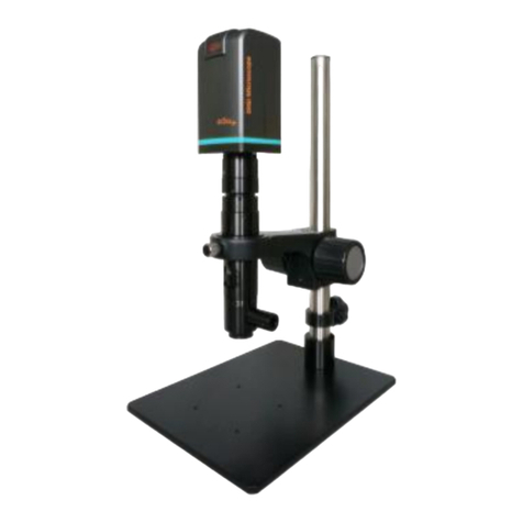
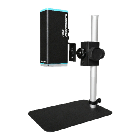
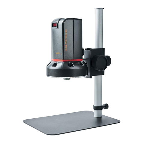
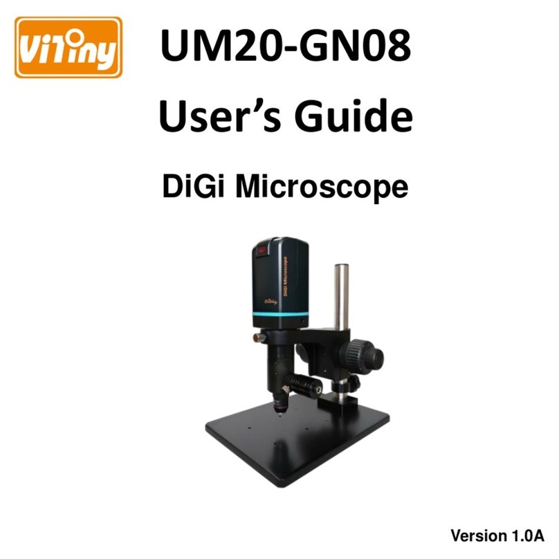
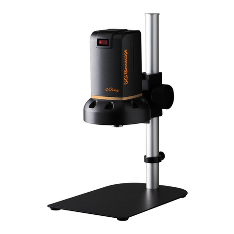
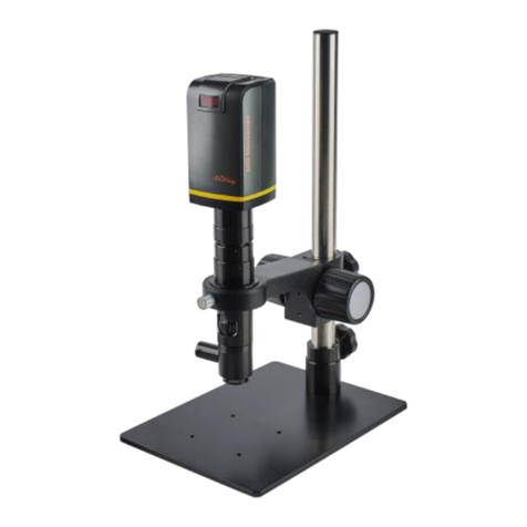
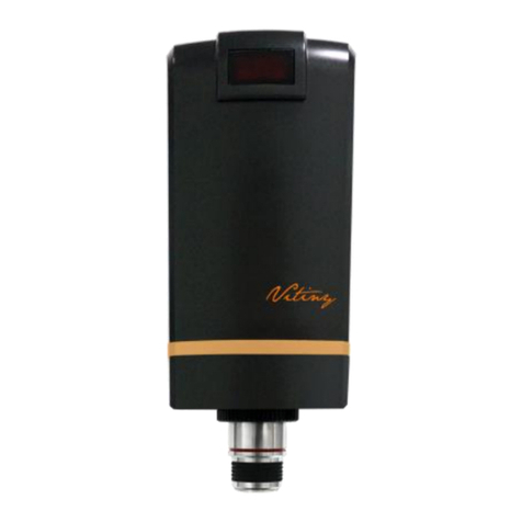
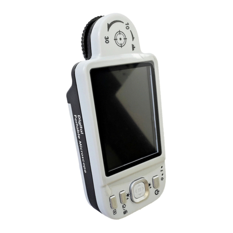
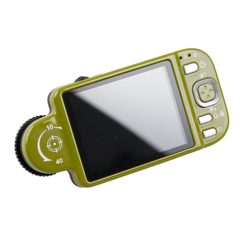
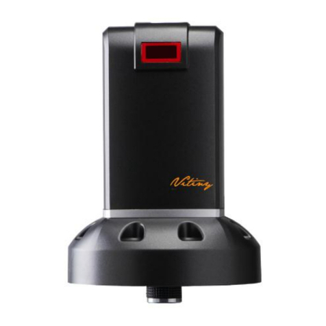
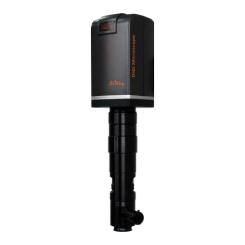
ViTiny DiGi UM06 User manual

User’s Guide
DiGi Microscope
Version 1.0A


1
Content
1. Products Introduction..........................3
1.1 Packing Contents .........................3
1.2 IR remote controller ....................3
1.3 Microscope introduction: ..........11
1.4 Microscope focus.......................14
1.5 Change microscope Object lens 17
1.6 Microscope accessory................20
2. Install Application Program ...............21
2.1 Insert CD to CD-ROM.................21
2.2 Install Application Program .......21
2.3 Exit Install Program....................21
3. Application Program Operation.........22
3.1 Video Preview Window .............23
3.2 Image Preview Window.............23
3.3 Main Menu ................................23
3.4 Main Button...............................23
3.5 Files List .....................................25

2
3.6 Function modes.........................25
4. Printed Notice....................................27
4.1 Maintenance..............................27
4.2 Product Specification.................28
4.3 Safety Instructions.....................29

3
1. Products Introduction
1.1 Packing Contents
There are 1 microscope and 10 accessories in the box. The Object Lens 4X is
already assembled onto microscope. If object lens needs to change, please refer to
Section 1.5.
Item
Q’ty
Item
Q’ty
DiGi Microscope
1
White Balance Card
1
HDMI Cable
1
Calibrator
1
USB 2.0 Cable
1
User’s Guide
1
Power adaptor
1
Install CD
1
S107 Stand
1
Object Lens 4x
1
Stand assemble guide
1
Object Lens 10x
Option
1.2 IR remote controller
The Digi Microscope is control by IR remote controller or application program.
When enable the far distance control mode from application program, the remote
controller is only used for Power, PC Cam or HDMI. There are 3 groups on the
remote controller to use in different mode: Common use, PC Cam and HDMI.
1.2.1 Buttons for Common use
The said buttons are used both for PC Cam and HDMI mode.
(1) Power :Turn on/off.
(2) LED Adjustment: Adjustable 12 levels of brightness.
(2-1) Increase :Increase LED brightness.
(2-2) Decrease :Decrease LED brightness.
(2-3) On/Off :Turn on or off the LED. When turn on the LED, the
brightness will return to the situation before turn off.
(3) Motor Reset (Calibrate of whole operation):To go back to the lens

4
position. If electricity black out occurred during operation, please reset the
whole operation.
(4) Manual focus
(4-1) Zoom in :Descending speed when press longer Zoom in.
(4-2) Zoom out :Descending speed when press longer Zoom out.
(4-3) Step zoom in :zoom in by steps.
(4-4) Step zoom out :zoom out by steps.
Microscope remote controller
Buttons for common use

5
1.2.2 Buttons for PC CAM
The said buttons are only used for PC Cam mode.
(1) PC CAM :When press the PC CAM mode, the USB cable has to connect with
PC and microscope. Please disable software before switch to HDMI mode or
turn off.
(2) Autofocus:This function only operates on PC Cam mode.
(2-1) Single Autofocus :Only focus one time.
(2-2) Continuous autofocus :Re-focus until the image is clear.
Buttons for PC CAM mode
Buttons for HDMI mode

6
(3) Snapshot :Take 5M picture and delivery to Application program.
1.2.3 Buttons for HDMI
The said buttons are only used for HDMI mode.
(1) HDMI :When press HDMI mode, the HDMI cable has to connect with
screen and microscope.
(2) Menu on Screen :Open/close menu for setting.
(2-1) BRIGHTNESS:To adjust the brightness of whole image. [1~31]
(2-2) CONTRAST:To emphasis the difference between bright and dark. [1~31]
(2-3) SATURATION:To adjust the color level. [1~31]
(2-4) EXPOSURE VALUE:On/Off the exposure [ON/OFF]。
[ON] Auto mode, use with exposure value +/-. The adjust method
please refer to Section 1.2.3-(7). This mode will adjust the image
brightness automatically. Please turn on all LED to keep the best
observation.
[OFF] Manual mode, use with LED brightness +/-. The adjust method
please refer to Section 1.2.1-(2) and Section 1.2.3-(7). This mode

7
inquires to adjust LED brightness and exposure value +/-. The image
brightness will change as the LED brightness and exposure value
changed.
(2-5) SHARPNESS:On/Off the sharpness. [ON/OFF]。
[ON] the image is sharp.
[OFF]the image is less-sharp, but more smooth.
(2-6) STATUS BAR:Show or not show the status bar on the screen top. please
refer to Section 1.2.3-(9).
[ON] show the status bar on the top of screen.
[OFF]close the status bar show on the screen.
(2-7) OBJECT LENS:Object lens type. (4x or 10x) When change another lens,
the setting needs to reset. Refer to Section 1.5.
[4X] Object Lens 4x, turn on LED for lens 4x; in opposite, turn off LED
for lens 10x.
[10X]Object Lens 10x, turn off LED for lens 4x; in opposite, turn on LED
for lens 10x.
(2-8) LCD SIZE:Screen size. The current setting is only for 7”~80”.
(2-9) FACTORY:All setting return to factory setting.
[NO]the current setting.
[YES]return to factory setting.
(3) Up :choose last item
(4) Down :choose next item
(5) Left :choose next value
(6) Right :choose last value
(7) Exposure Value: 13 levels of exposure value is selectable, from +0.2~-2.0.
(7-1) Increase :when the image is darker, add exposure value.
(7-2) Decrease :when the image is brighter, decrease exposure value.

8
(8) Video Ratio :Choose image ratio or Field of View. There are 3 types of
video ratio, press the button to next ratio.
(8-1) 4/3F:4:3 means the image is from 5M image (2592*1944) output to fit
4:3 screen size. (The screen image: 1440*1080). Proportionally reduce
the input image height to fit the screen.
(8-2) 16/9S:16:9S means the image from 5M (2592*1944) output to 16:9
screen size (the screen image: 1920*1080). Reduce input image
horizontal proportionally to fit the screen, but trim the height.
(Scaling) Magnification size becomes higher.

9
(8-3) 16/9C:16:9C means the image from 5M (2592*1944) output to 16:9
screen size (the screen image: 1920*1080). Crop image (1920*1080)
from input image 5M (2595*1944); therefore, FOV become smaller,
magnification become higher.
(9) Status Bar : On/Off to show or not show the status bar. Each color
represents different information.

10
(9-1) ZOOM:Zoom path, total 15 sections.
(9-2) FOV:Field of View, display image on the effective horizontal size of screen.
(9-3) M:Magnification. Magnification size changes depending on lens position,
screen size, and image ratio. Please refer to Section 1.4.2.
(9-4) D:Distance, means the distance from object lens to object.
(9-5) EV:Exposure Value, please refer to Section 1.2.3-(7).
(9-6) LED:LED Levels, please refer to Section 1.2.1-(2).
(9-7) R:Video Ratio, please refer to Section 1.2.3-(8).
(10) Auto White Balance Calibration : Place the White balance card (included in
box) under the lens, firstly focus til clear then choose On to calibrate white
balance. Sometimes the white balance is influenced by environment light
source or other light source, thus it’s suggested to calibrate white balance if
the color is not correct.

11
(11) Image Freeze : On/Off image freeze. Freeze the image, press the button
again to return to preview.
(12) Sharpness : On/Off sharpness mode. Please refer to Section 1.2.3-(2).
1.3 Microscope introduction:
1.3.1 IR Remote area/Indicator
When both HDMI and USB indicator light on means the microscope is turn off.
(1) IR remote control aiming area ○
a
(2) HDMI indicator○
b: When light up means HDMI mode.
(3) USB indicator○
c: When light up means USB mode. Light flicker means
microscope does not connect with PC.
○
b
○
c
○
a

12
1.3.2 Power/USB/HDMI port
(1) Power○
d: Please only use the power supplier from the box, do not use any
other power supplier.
(2) USB○
e: USB port for connecting application program. When using PC Cam
mode, please connect the microscope to PC by using the USB cable from the
box. (firstly to connect USB cable to microscope and PC then secondly switch
to PC Cam mode)
○
e
○
d

13
(3) HDMI○
f:HDMI port for connecting screen. When using HDMI mode, please
connect the microscope to screen by using the HDMI cable from the box.
*Note: if connect with TV screen, please choose the homologous image ratio
and format.
1.3.3 Stand gear box
The universal joint as ○
g. Firstly, assemble the stand then screw microscope to the
universal joint on gear box and fixed on stand.
○
g
○
f

14
1.3.4 LED/ Light socket
(1) LED○
h: Luminance for object lens 4x, total 30pcs LEDs with angle. 6pcs as fig
have wider angle for purpose.
(2) Light socket○
i: Luminance for object lens 10x.
1.4 Microscope focus
There are two ways to focus. First, to choose focus distance to adjust the
microscope height, then tuning focus by remote controller until clear. On the
contrary, first to choose the image sensor position then adjusts the microscope
height.
Focus distance: distance from object lens to object.
Image sensor position: The image sensor position.
1.4.1 Way of Focus
(1) Fixed focus distance
Use knob ○
jor ○
kto adjust the distance from object lens to object. When
the distance is closer, the magnification size is higher. When fixed the focus
distance, using remote controller or far distance control mode on application
○
i
○
h

15
program to tuning to clear image.
(2) Fixed image sensor position
(2-1) In HDMI mode, the status bar will show on the screen, please refer to
Section 1.2.3-(9). Use remote controller to adjust image sensor position
based on magnification size, FOV, or distance height.
(2-2) In PC CAM mode, choose required height or FOV from drop down list on
application program (see below fig).
When image sensor position is fixed, as (2-1) and (2-2), use knob ○
j& ○
kto
find clear image. Adjust the knob ○
jin the beginning to the appropriate
height, then slightly adjust the knob ○
kto find clear image.
○
j
○
k
○
j
○
k

16
1.4.2 Magnification chart
15 image sensor positions had set from the whole area, the image sensor
position tells the magnification size, field of view, or height. The below
chart is measured on 21.5” screen, it’s only a reference data, might not be
accurate enough. Based on the image ratio, field of view and magnification
size will change. Please refer to “F”, “S”, “C” in Section 1.2.3 –(8).
(1) Object lens 4X, focus distance from 1.95cm to 22cm (0.767 to 8.66inch).
Object lens 4X on 21.5” screen
Sensor position
1
2
3
4
5
6
7
8
Distance
22.0
15.2
9.70
7.35
5.75
4.75
4.15
3.65
F,S FOV
27.0
18.4
11.9
9.02
7.10
5.88
5.05
4.40
C FOV
19.9
13.6
8.80
6.67
5.25
4.35
3.73
3.25
F Magnification
13
20
30
40
50
61
71
81
S Magnification
17
26
40
53
67
81
95
109
C Magnification
23
34
54
70
90
109
127
145
Sensor position
9
10
11
12
13
14
15
unit
Distance
3.30
2.85
2.65
2.45
2.30
2.10
1.95
cm
F,S FOV
3.91
3.50
3.19
2.91
2.68
2.48
2.34
mm
CFOV
2.89
2.59
2.36
2.15
1.98
1.83
1.73
mm
F Magnification
92
102
112
123
134
145
154
X
S Magnification
122
137
150
164
179
193
205
X
C Magnification
165
183
201
221
241
261
277
X

17
(2) Object lens 10X, focus distance from 4.5mm to 7.7mm (0.177 to 0.303inch.
1.5 Change microscope Object lens
Object lens 10x is optional accessory. It comes with luminance, thus power
supplier is needed. Please remove the power cable before change object lens.
1.5.1 Remove LED cover ○
l
Unscrew 3 pc screws to remove LED cover.
Object lens 10X on 21.5” screen
Sensor position
1
2
3
4
5
6
7
8
Distance
7.70
7.10
6.70
6.40
6.10
5.89
5.60
5.41
F,S FOV
1.39
1.30
1.21
1.14
1.07
1.01
0.96
0.91
C FOV
1.02
0.96
0.89
0.84
0.79
0.74
0.71
0.67
F Magnification
260
279
297
318
336
360
378
395
S Magnification
346
371
395
423
447
479
503
526
C Magnification
468
502
534
572
604
648
680
711
Sensor position
9
10
11
12
13
14
15
unit
Distance
5.27
5.10
4.96
4.84
4.73
4.62
4.51
mm
F,S FOV
0.87
0.83
0.79
0.76
0.73
0.70
0.68
mm
C FOV
0.64
0.61
0.58
0.56
0.54
0.52
0.50
mm
F Magnification
413
439
455
480
493
145
154
X
S Magnification
550
585
606
639
657
694
705
X
C Magnification
743
790
819
964
887
937
952
X

18
1.5.2 Connect power cable
Plug in the power cable○
monto LED board socket○
n. Pass through the
power cable out of LED cover○
o. When remove, please never pull and drag
the power cable from inappropriate force, and hold the cable thread when
disassemble.
○
m
○
n
○
o
○
l
Other manuals for DiGi UM06
1
Table of contents
Other ViTiny Microscope manuals

ViTiny
ViTiny VT300 PLUS User manual

ViTiny
ViTiny UM-CAM User manual

ViTiny
ViTiny UM30 User manual

ViTiny
ViTiny UM08-CSZ064 User manual

ViTiny
ViTiny UM08-GN User manual

ViTiny
ViTiny DiGi UM10 User manual

ViTiny
ViTiny UM20B-CSZ064 User manual

ViTiny
ViTiny UM20D-CSZ064 User manual

ViTiny
ViTiny VT300-O User manual

ViTiny
ViTiny UM22 User manual

ViTiny
ViTiny UM20A-CSZ064C User manual
ViTiny
ViTiny Fun 50 User manual

ViTiny
ViTiny UM08B-CSZ064 User manual

ViTiny
ViTiny VT101 User manual

ViTiny
ViTiny VT300 User manual
ViTiny
ViTiny UM20-CSZ1236 User manual

ViTiny
ViTiny UM20-GN User manual

ViTiny
ViTiny UM06-CSZ064C User manual

ViTiny
ViTiny UM20-GN08 User manual
ViTiny
ViTiny PRO10 User manual