Vivax ACP-09CH25GEH User manual
Other Vivax Air Conditioner manuals

Vivax
Vivax ACP-18COFM50AECI User manual

Vivax
Vivax ACP-12CH35AEEI PRO User manual

Vivax
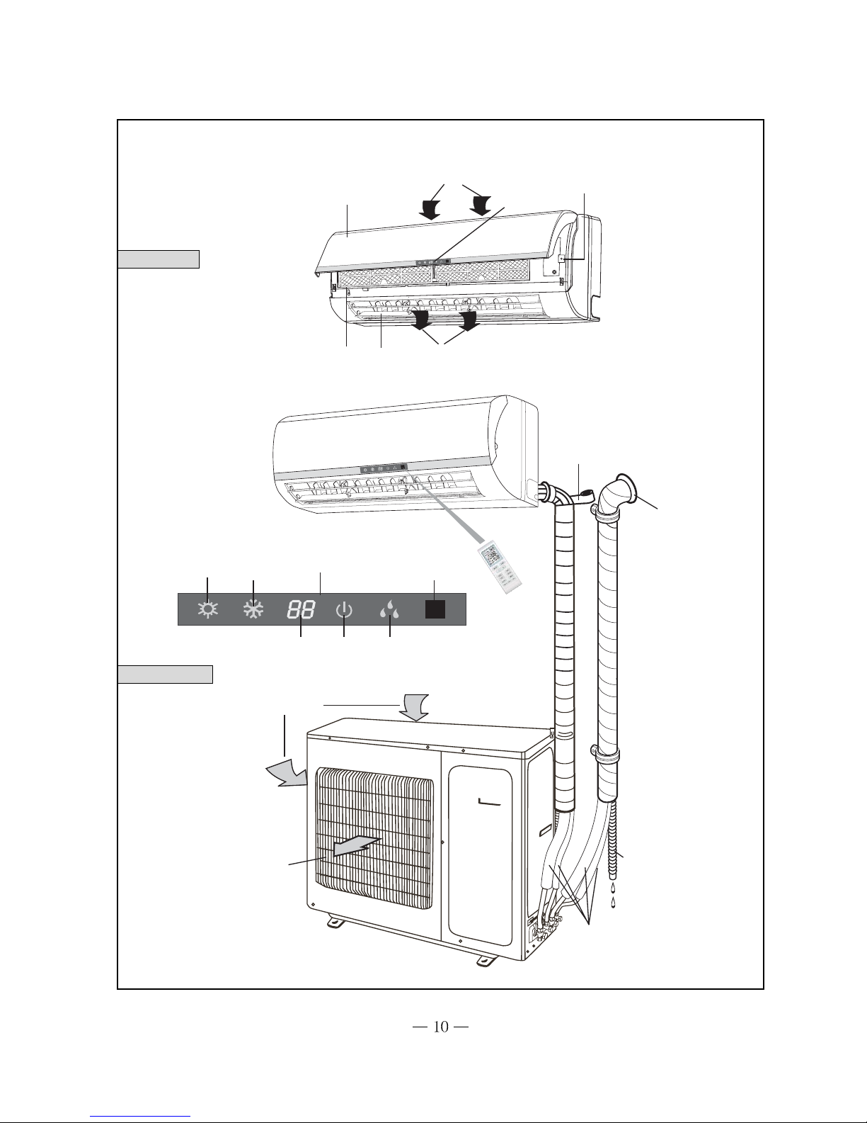
Vivax HPS-42HM84AERI/I1s User manual

Vivax
Vivax ACP-12CH35GEDI User manual

Vivax
Vivax ACP-18CF50GEI User manual

Vivax
Vivax ACP-12CT32AEI/I User manual

Vivax
Vivax ACP-09CH25GETI User manual

Vivax
Vivax V DESIGN ACP-12CH35AEVI GOLD User manual

Vivax
Vivax M-DESIGN R32 User manual

Vivax
Vivax ACP-24CC70AERI2 User manual

Vivax
Vivax ACP-09PT25AEF User manual

Vivax
Vivax ACP-09CH25AEI User manual

Vivax
Vivax ACP-12DT35AERIs R32 User manual

Vivax
Vivax ACP-24CH70AEB User manual

Vivax
Vivax ACP-09CH25GECI User manual

Vivax
Vivax ACP-12CH35AEHI+ User manual

Vivax
Vivax ACP-12CF35AERIs R32 User manual

Vivax
Vivax Y-DESIGN ACP-09CH25AEYIs R32 User manual

Vivax
Vivax ACP-09CH25AEF User manual

Vivax
Vivax ACP-09CH25AEM User manual


Popular Air Conditioner manuals by other brands


CIAT
CIAT Magister 2 Series Installation, Operation, Commissioning, Maintenance

Bestron
Bestron AAC6000 instruction manual

Frigidaire
Frigidaire FFRE0533S1E0 Use & care guide

Samsung
Samsung AS09HM3N user manual

Frigidaire
Frigidaire CRA073PU11 use & care

Soleus Air
Soleus Air GB-PAC-08E4 operating instructions

McQuay
McQuay MCK020A Technical manual

Webasto
Webasto Frigo Top 25 DS Instructions for use

Frigidaire
Frigidaire FAZ12ES2A installation instructions

Mitsubishi Electric
Mitsubishi Electric MSC-GE20VB operating instructions

Mitsubishi Electric
Mitsubishi Electric PLA-M100EA installation manual

Daikin
Daikin Split Sensira R32 Service manual