9/19
(III) To share network access with a PC / network client
Users may connect a laptop computer to V656IP(1D) WIFI.
Before you proceed, make sure V656IP(1D) WIFI has already obtained an IP address.
V656IP(1D) WIFI must function as a Wi-Fi client in order to share network access with another
device.
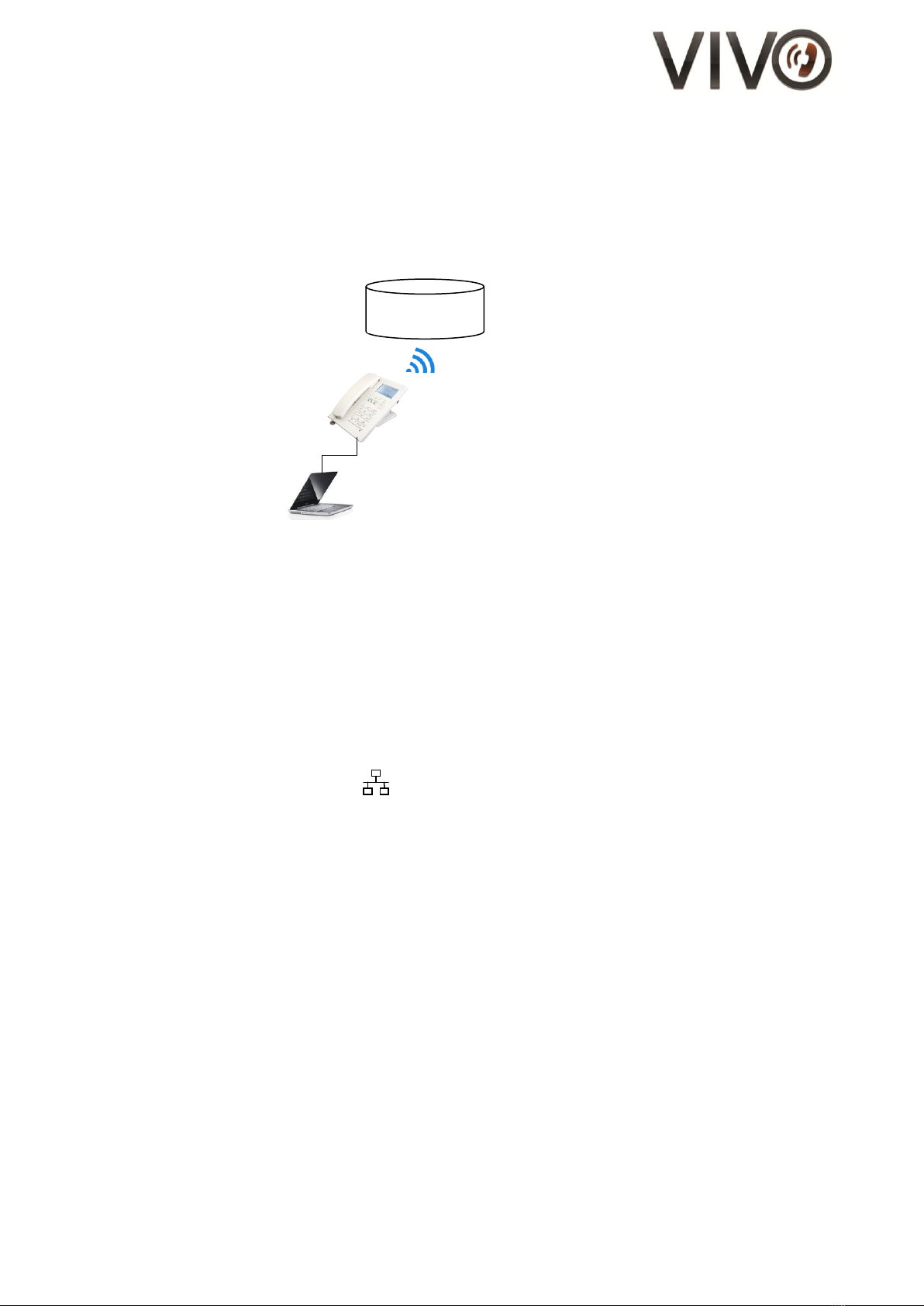
Figure 10 –Illustration of connecting a laptop to V656IP(1D) WIFI
1. Log on to the WebPortal of V656IP(1D) WIFI
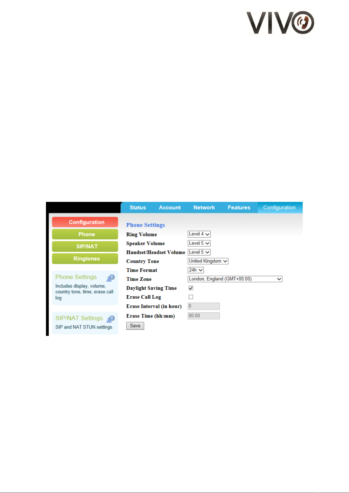
2. Go to Network section
3. Select “Switch mode” for Net Operation Mode
- In Switch mode, the laptop computer will be assigned in the same subnet as the Wi-Fi router
- in Router mode, the V656IP(1D) WIFI will assign laptop computer’s IP address
4. Find the Save button at the bottom of the page and click on it
5. This will take you to the confirmation page. Click “Reboot”
6. Wait approximately 25 seconds and see that the LED for MWI blinks twice
7. Plug in one end of the Ethernet cable to the laptop and another end to the WAN port of
V656IP(1D) WIFI labelled,
The Wi-Fi connection is now shared with your laptop computer
C. Call Operation
(I) Initiating a Call
1. Lift the handset.
2. Listen to dial tone.
3. Press the desired number on the keypad and wait for 5 second or press “#” to dial out.
4. To end the call, place the handset back on the cradle in the base unit.
(II) Answering a Call
An incoming call to the phone.
An audible ringing sound to alert the user.
LED on the top right corner flashes.
1. Lift up the handset to answer the call.
2. To end the call, place the handset back on the cradle. The LED will turn off.