VOLT TIME Source 2 Assembly instructions

Installation Guide
Alternative cable entry
Source 2
EN Installation & Setup Guide

Volt Time Source 2 Installation Guide - alternative entry
Table of Contents
Introduction 3
Product overview 4
Before installation 5
Installation 6
Installation procedures 7
Installing the App 8
Installing the mounting plate 9
Mounting the Source 2 10
Connecting the cables 11
Configure the product 13
Finalise the installation 14
Product interface 15
2

Volt Time Source 2 Installation Guide - alternative entry
Introduction
Before installing the product, please read the important
product and safety guide at volttime.com/manuals. Here
you can also find other versions and languages.
This installation and setup guide includes:
●Mounting and wiring up Source 2
●Configure the product
●LED status description
To install and configure a Volt Time charger, a mobile device
with an internet connection is required as well as an
internet source connected to the charger (Ethernet or an
optional 4G LTE connection).
WARNINGS AND CAUTIONS
Whenever a condition, hazard or unsafe practice can result
in serious personal injury or death, a WARNING will be
indicated.
WARNING:Volt Time stipulates that the installation as well
as all maintenance or reparation on this product must be
performed by a certified electrician. All applicable local,
regional and national regulations for electrical installations
must be followed.
3
Volt Time Source 2 Installation Guide - alternative entry
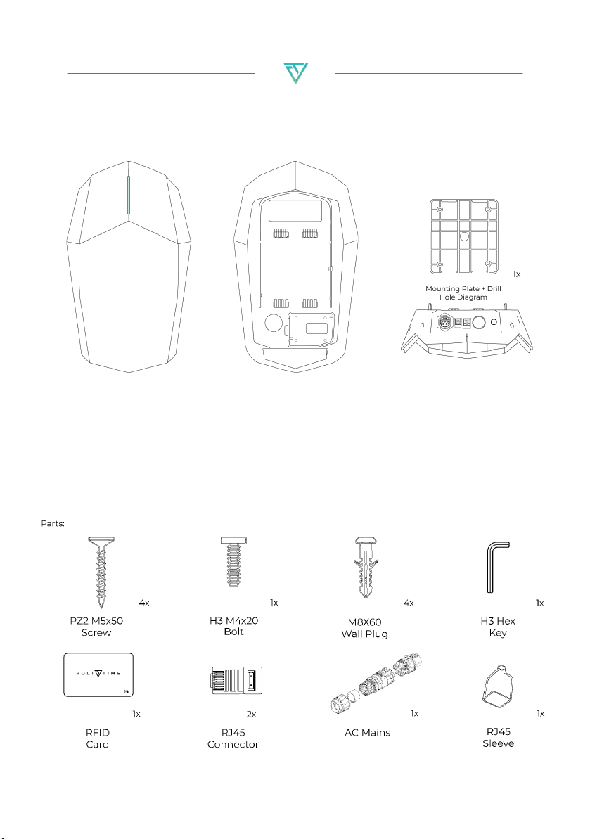
Product overview
ront
D indicator and RFID sensor on
e front of the casing.
ack
ntains all the electronics
ternally to charge your vehicle,
th easy mounting options on
e back.
onnectivity
th three connectivity ports at
e bottom, the installation is
ade completely plug-and-play.
4

Volt Time Source 2 Installation Guide - alternative entry
Before installation
The following prerequisites are mandatory to fully commission
the product:
●A mobile device with internet connection.
●Volt Time “Installer App” on a mobile device.
●The product with an internet connection.
Without the Business Upgrade the product
requires a CAT5(e) ethernet cable for internet.
●Upstream Circuit Breaker and RCD Type A (30mA).
●Load & Solar Module requires an (extra) CAT5(e)
ethernet cable.
●Please install the protection covers into the RJ12 and
RJ45 ports at the bottom of the product.
Optimal charging
For an optimal charging experience the following is
recommended:
●To avoid overloading the main fuses of the building
the Load & Solar module is recommended. This
module will dynamically adjust the maximum
current of the product and provides the option to
charge fully on surplus Solar Energy.
To install the Load & Solar module, go to
https://volttime.com/manuals to download the Load
& Solar module alternative entry manual.
●A 3-phase installation of the product is
recommended if possible.
●Always use the largest available cable cross-section.
The entry via the back can go up to 10mm2.
CAUTION:The grid type as well as cable-cross sections should
be determined by the electrician before installing the product.
5

Volt Time Source 2 Installation Guide - alternative entry
Installation
WARNING:Prior to the installation of the product, the power
supply must be switched off. Make sure to follow this manual
closely, and with extreme caution.
The instructions and procedures discussed in this manual must
be followed and applied at all times, or it will result in an
invalidated installation. This will cause Volt Time B.V. and its
partners to waive all liability and claims for compensation.
Installations and maintenance on this product must only be
performed by qualified and authorised personnel. Any technical
support or repairs on the product must be executed by Volt
Time or a pre-approved Volt Time certified company.
All applicable local, regional and national laws and regulations
must be adhered to at all times.
Do not install or use the product in case of damage as it can
lead to unsafe or hazardous conditions which may result in
electrical shock or (potentially fatal) injury.
Avoid placing the product in a location exposed to direct
sunlight or extreme weather/temperature conditions.
6

Volt Time Source 2 Installation Guide - alternative entry
Installation procedures
Source 2 has two types of installation procedures which should
be determined before starting the installation.
●Installing the product via the entry on the rear
(maximum cable-cross section is 10mm2).
●Installing the product with the AC Mains Connector
set (maximum cable-cross section is 6mm2).
To install the product using the entry on the rear, follow this
document.
For installations using the AC Mains Connector, scan the
following QR code to find Installation Guide:
Or go to https://volttime.com/manuals to download the
manual for wiring through the back.
7

Volt Time Source 2 Installation Guide - alternative entry
Installing the App
1. Scan the QR code to download the Volt Time Installer App and
create a free account.
2. Log in with your (newly created) Installer account.
3. Enter the serial number and unique pincode found on the side
and bottom of the product respectively.
4. Check the installation requirements via the installer app and
return to this guide afterwards.
Or go to https://volttime.com/installer to install the Volt Time
Installer App to your mobile device.
8

Volt Time Source 2 Installation Guide - alternative entry
Installing the mounting plate
1. Hold the mounting plate drawing against the wall and make
sure it is level.
2. Recommended installation height is 120cm. Minimum
installation height is 90cm.
3. The drawing has 4 screw locations. Drill these 4 holes with an
8mm drill bit.
4. The drawing has 1 big drill hole at the bottom. Drill this hole
with a 25mm drill bit so that the AC mains cable can be
connected through the back of the charger.
5. Push M8 wall plugs (4x) into the drilled holes.
6. Place the mounting plate with the flat edge against the wall
and the slits of the mounting plate pointing up- and
downwards.
7. Screw the mounting plate against the wall using PZ2 screws
(4x).
CAUTION:The installation wall must cover the entire backplate
and should be perfectly flat.
9

Volt Time Source 2 Installation Guide - alternative entry
Mounting the Source 2
Before mounting the Source 2, unscrew the 9 screws at the
back of the product and take off the cover.
CAUTION: For a socket variant, the cover can not be stored
separately as wires will still be connected to the internals.
Proceed with caution.
1. Cut the tip from the throughput on the back of the product as
well as 4 extra cuts 90 degrees from each othe.
2. Gently push the AC Mains cable through the throughput.
- (Optionally) Push one (or two) CAT5(e) ethernet cable(s)
through the throughput for an internet connection and/or
Load Management installation. Source 2 without Business
Upgrade requires at least one ethernet cable for an
internet connection.
3. Place the product over the mounting plate so that the
mounting hooks fit into the 4 slits of the plate.
4. Slide the product downwards until it snaps in place. Do not
lock the product onto the mounting plate yet with the locking
bolt.
10
Other manuals for Source 2
1
Table of contents
Other VOLT TIME Batteries Charger manuals


