5678
AC voltage measurement: true RMS value, DC voltage measurement: average value
Resistance
measurement
Continuity test
* rdg.: reading or displayed value, dgt.: resolution
Check the following before using the instrument.
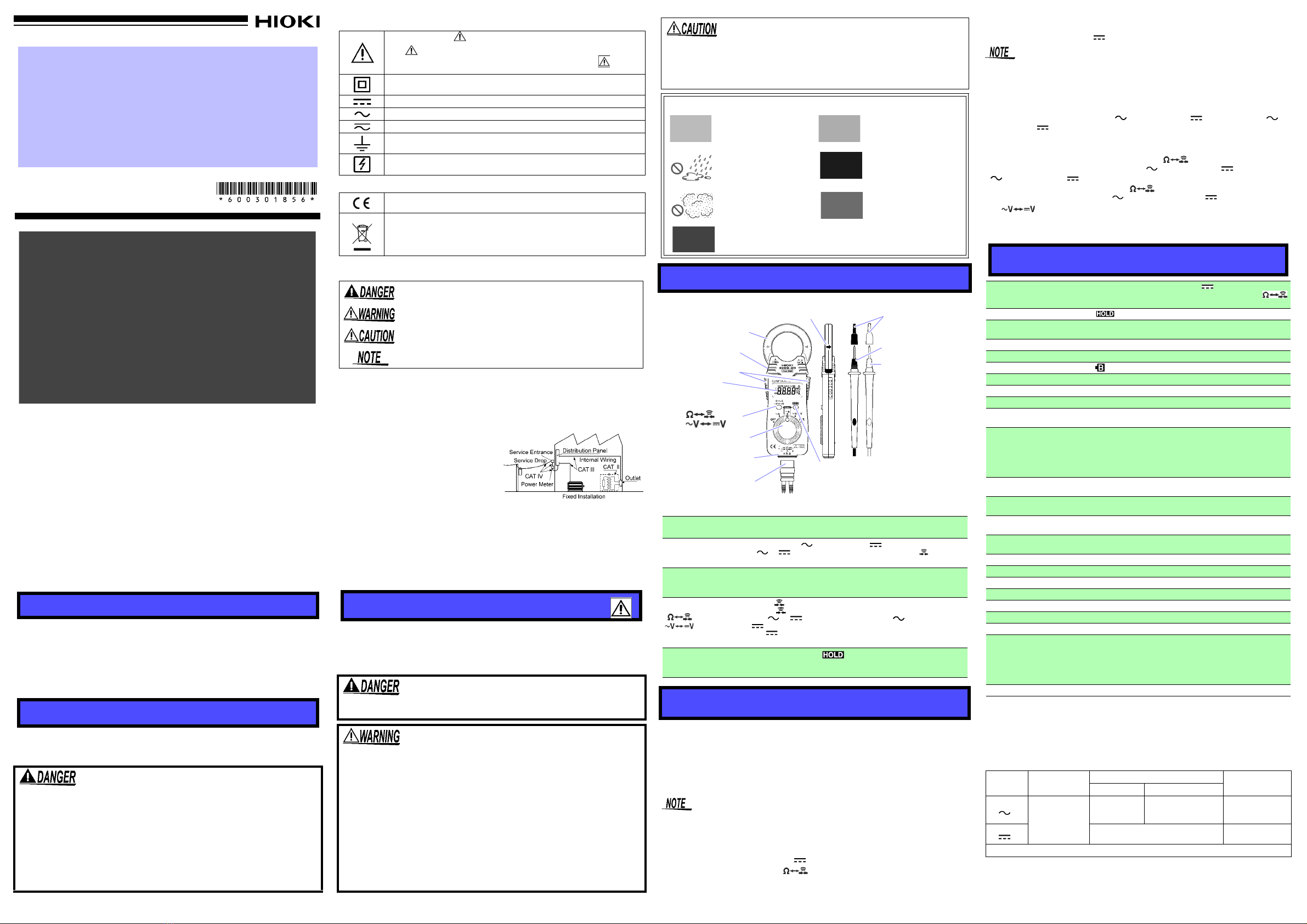
Measuring AC Current [ A]
1. Set the function selector to A.
2. Clamp the tester on the conductor, so that
the conductor passes through the center of
the clamp core.
Measuring DC Current [ A]
1. Set the function selector to A.
2. After making sure that there is not input to the instru-
ment, perform zero adjustment by simultaneously
pressing the and HOLD keys.
3. Clamp the line to be measured so that the arrow on the
side of the clamp sensor points in the direction of cur-
rent flow and the line is position in the center of the
sensor jaws. (A negative reading will result if the arrow
points in the opposite direction.)
Measuring AC Voltage [ V]
1. Set the function selector to V/ V.
2. Connect the test leads to the object to be measured. When measuring AC
voltage, the polarity of the leads can be ignored.
Measuring DC Voltage [ V]
1. Set the function selector to V/ V.
2. Press key to display V.
3. Connect the red (+) lead to the +side of the circuit to be measured and the
black (-) lead to the -side. A negative reading will result if the leads are
reversed.
Plug the test leads into the measurement terminal.
1. Set the function selector to
/.
2. Connect the test leads to the object to be measured.
Plug the test leads into the measurement terminal.
1. Set the function selector to
/.
2. Press the key, so that the indication appears.
3. Connect the test leads to the object to be measured. Conductivity is good
when the beep sounds.
1. Remove the instrument and the test leads from the
test item, and power the instrument off.
2. Remove the instrument from the case, and
remove the screws on the battery cover.
3. Remove the used battery.
4. Being careful about the polarity, insert the new
battery of the specified type. (CR2032 lithium
battery: Panasonic or MAXELL)
5. Replace the battery cover and fasten the screws.
To clean the instrument wipe it gently with a soft cloth moistened with water or
mild detergent. Never use solvents such as benzene, alcohol, acetone, ether,
ketones, thinners or gasoline, as they can deform and discolor the case.
When the instrument is not functioning properly and if you have not performed
the pre-operation inspection, please do so now. If you cannot find a problem in
the pre-operation inspection, please refer to the following symptoms before con-
tacting your dealer or the nearest Hioki representative. When you send the unit
for repair, please pack the unit carefully so that it will not be damaged during
transport, and write a detailed description of the problem. Hioki cannot bear any
responsibility for damage that occurs during shipment.
Function Range
(Accuracy range) Accuracy
±(%rdg.+dgt.)*
Input
impedance Max. input
voltage
ACV
( V)
4.200 V (0.400 to 4.199 V)
42.00 V (4.00 to 41.99 V)
420.0 V (40.0 to 419.9 V)
600 V (400 to 600 V)
±(2.3%+8)
30 to 500 Hz
11 M±5%
10 M±5%
10 M±5%
10 M±5%
600 V rms AC
DCV
( V)
420.0 mV (40.0 to 419.9 mV)
4.200 V (0.400 to 4.199 V)
42.00 V (4.00 to 41.99 V)
420.0 V (40.0 to 419.9 V)
600 V (400 to 600 V)
±(1.3%+4)
100 Mor more
11 M±5%
10 M±5%
10 M±5%
10 M±5%
600 V DC
Function
Range
(Accuracy range) Accuracy
±(%rdg.+dgt.)*
Open terminal
voltage
Overload
protection
420.0
(40.0 to 419.9
)
4.200 k
(0.400 to 4.199 k
)
42.00 k
(4.00 to 41.99 k
)
420.0 k
(40.0 to 419.9 k
)
4.200 M
(0.400 to 4.199
)
42.00 M
(4.00 to 41.99
)
±(2.0%+4)
±(2.0%+4)
±(2.0%+4)
±(2.0%+4)
±(5.0%+4)
±(10.0%+4)
3.4 V or less
0.7 V (typ.) 3.4 V or less
0.47 V (typ.) 3.4 V or less
0.47 V (typ.) 3.4 V or less
0.47 V (typ.) 3.4 V or less
0.47 V (typ.) 3.4 V or less
250 V
AC/DC
Function Range Accuracy
±(%rdg.+dgt.)* Threshold level
(beep sound) Open terminal
voltage Overload
protection
420.0 ±(2.0%+6) Less than 50 ±40 3.4 V or less 250 V
AC/DC
Measurement Procedures
After turning on the instrument and changing over the functions, it could take a
dozen seconds to stabilize the display.
Check items Diagnose and Solution
Check whether the cladding of the test
lead is not torn and the white or red por-
tion (insulation layer) inside the cable is
not exposed.
When damage is found, replace with the
specified new test leads Model L9208. Fail-
ure to do so may result in electric shock.
Check whether the clamp sensor or the
case is free of damage. If damage is present, avoid using the instru-
ment. Use of the instrument under these con-
ditions may result in electric shock.
Make sure that the mating portion of the
clamp sensor tip is mate properly. If the mating portions do not mate properly,
accurate measurements cannot guaranteed.
Gently wipe off any dirt with a soft cloth found
on the surface of the mating portions. If the
sensors do not mate properly, repair is nec-
essary.
Make sure there are no missing display
of the LCD panel. If missing, repair is necessary.
Make sure that the display of the LCD
panel is not dim or faint. If the display is dim or faint, the environmen-
tal condition may be low temperature (lower
than 0°C) or battery may be exhausted. In
case of battery exhaustion, replace battery.
If the display remains dim even after the bat-
tery is replaced, repair is necessary.
Make sure that the battery indicator " "
does not light up when power is turned
on.
If the indicator is on, the measurement accu-
racy cannot be guaranteed. Replace battery
immediately.
Check whether Zero adjustment can be
made by pressing both key and
HOLD key simultaneously in DC current
measurement mode.
If Zero adjustment cannot be made, accurate
measurement is not possible. Repair is nec-
essary.
Check whether the reading is around 0 A
when no measurements are being made
in AC current measurement mode.
(Although there is the case that the read-
ing is around 0.1 A, the accuracy of mea-
surement can be guaranteed as it is.)
When some large value is displayed, some-
thing is wrong with the instrument. Repair is
necessary.
(See-Troubleshooting)
Check whether the reading is around 0 V
while the test leads are short-circuited in
voltage measurement mode. (Although
there is the case that the reading is
around 0.01 V in AC voltage measure-
ment mode, the accuracy of measure-
ment can be guaranteed as it is.)
If the reading is not around 0 V, check
whether the test leads are open circuit or not.
When no open circuit condition is present,
the instrument itself needs repair.
Make sure that an abnormal value is not
displayed when a known value is mea-
sured in voltage measurement mode.
If an abnormal value is displayed, repair is
necessary.
Check whether the reading is around 0
while the test leads are short-circuited in
resistance measurement mode. (Check
for open circuit in the test leads)
If the reading is not around 0
, replace the
test leads Model L9208.
Check whether the "O.F" appear when
moving the test leads apart. If the "O.F" does not appear, repair is neces-
sary.
Check whether a beep sound is gener-
ated when the test leads are short-
circuited in continuity test mode.
When the test leads are not open circuited
and no beep sound is generated, repair is
necessary.
Observe the following precautions to avoid electric shock.
• Always verify the appropriate setting of the function selector
before connecting the test leads. Disconnect the test leads
from the measurement object before switching the function
selector.
• Never apply voltage to the test leads when the Resistance, or
Continuity Test functions are selected. Doing so may damage
the instrument and result in personal injury. To avoid electrical
accidents, remove power from the circuit before measuring.
• Removable sleeves are attached to the metal pins at the ends of the test
leads. To prevent a short circuit accident, be sure to use the test leads with
the sleeves attached when performing measurements in the CAT III mea-
surement category. Remove the sleeves from the test leads when perform-
ing measurements in the CAT II measurement categories. For details on
measurement categories, see "Measurement categories" in the instruction
manual.
• When performing measurements with the sleeves attached, be careful to
avoid damaging the sleeves. If the sleeves are inadvertently removed dur-
ing measurement, be especially careful in handling the test leads to avoid
electric shock.
• The tips of the metal pins are sharp, so take care not to injure yourself.
• Be careful to avoid dropping the instrument or otherwise subjecting them to
mechanical shock, which could damage the mating surfaces of the core
and adversely affect measurement.
Current Measurement
The maximum rated voltage between input terminals and
ground is CAT III 600 V. In current measurement mode,
attempting to measure voltages exceeding CAT III 600 V
with respect to ground could damage the instrument and
result in personal injury.
Do not exceed the maximum input current rating. Doing so may
cause the heat generation of clamp sensors and result in damage to
the instrument or burn injuries.
Attach the clamp around only one conductor.
㪇
㪉㪇㪇
㪋㪇㪇
㪍㪇㪇
㪏㪇㪇
㪈㪇㪇㪇
㪈㪉㪇㪇
㪈㪇 㪈㪇㪇 㪈㪇㪇㪇
㪠㫅㫇㫌㫋㩷㪽㫉㪼㫈㫌㪼㫅㪺㫐㪲㪟㫑㪴
㪠㫅㫇㫌㫋㩷㪺㫌㫉㫉㪼㫅㫋㪲㪘㪴
Figure 1. Permissible current to frequency
Voltage Measurement
• The maximum input voltage is 600 V AC/DC. Attempting to
measure voltage in excess of the maximum input could
destroy the instrument and result in personal injury or death.
• To avoid electrical shock, be careful to avoid shorting live
lines with the test leads.
• In voltage measurement mode, the maximum rated voltage
between input terminals and ground is CATIII 300 V, CAT II 600 V.
In current measurement mode, attempting to measure voltages
exceeding CATIII 300 V, CAT II 600 V with respect to ground
could damage the instrument and result in personal injury.
Make sure that the test lead plug is inserted into the measurement terminal of
the instrument correctly.
Resistance Measurement []
Continuity Test [ ]
Replacing Battery
• If the instrument is connected to a line that is to be measured,
dangerous voltage levels may be applied to the terminals, and
removing the case may expose live components. To avoid
electric shock when replacing the battery, first disconnect the
instrument and the test leads from the object being measured.
Also, after replacing the battery, always replace the cover and
tighten the screw before using the instrument.
• Use only CR2032 (Panasonic or MAXELL) lithium battery. Use
of any other battery may result in explosion.
• Battery may explode if mistreated. Do not short-circuit,
recharge, disassemble or dispose of in fire.
• Be sure to insert them with the correct polarity. Otherwise,
poor performance or damage from battery leakage could
result. Replace batteries only with the specified type.
• Handle and dispose of batteries in accordance with local reg-
ulations.
• Keep batteries away from children to prevent accidental swal-
lowing.
• When the battery is exhausted, the “ ”indication appears in the display.
• The battery included with this instrument was inserted for Testing Purposes
only. Battery life will vary. Please replace the original battery with a new bat-
tery as soon as it is depleted.
• CR2032 lithium batteries (Panasonic or MAXELL) can be purchased at elec-
tronics and appliance stores where specialized batteries are sold.
• Do not turn the adjustment screws as this may disrupt the measurement val-
ues.
• Do not overtighten the screw on the battery cover. Doing so may damage the
main body of the instrument (recommended tightening torque: 0.1 N/m).
Maintenance and Service
Troubleshooting
Symptom Description
The measured value of
current or voltage is different
from the measured value
with other clamp-on tester.
• Waveform containing components out of the
frequency property range cannot be mea-
sured accurately.
• In the case that the sample to be measured is
a distorted waveform, the measured value with
the 3288-20 and that with another clamp-on
tester using MEAN value method (Average
value rectified, effective value display) are dif-
ferent. Using true RMS method, the 3288-20
can measure such a waveform accurately.
• In the case that the sample to be measured
is the waveform with both AC and DC com-
ponents, half or full-wave rectified waveform,
accurate measurement is not be possible
due to the large margin of error. We recom-
mend using another instrument with AC+DC
mode.
The measured current value
is smaller than expected.
• The measurement value is not correct, if the
measurement is performed leaving the clamp
jaws open.
The measured current value
is larger than expected.
(current value is displayed
even with no input.)
• Accurate measurement is not possible in the
presence of strong magnetic fields, such as
transformers and high-current conductors, or
in the presence of strong electromagnetic
fields such as radio transmitters.
Roaring sound is heard
around the clamp sensors.
When the current of the sample is higher than
500 A or the frequency is higher than 200 Hz,
the roaring sound may be generated from the
clamp sensors.
Battery
cover
Battery
Adjustment screws
Screw
CALIFORNIA, USA ONLY
This product contains a CR Coin Lithium Battery which contains
Perchlorate Material - special handling may apply.
See www.dtsc.ca.gov/hazardouswaste/perchlorate