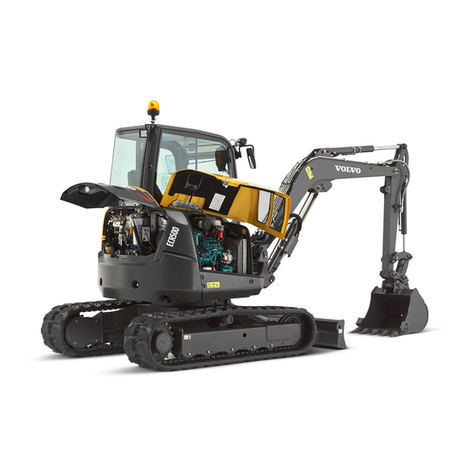
Volvo ECR25 Electric User manual

PUB 20057955-A 2020.10 English
OPERATOR'S MANUAL ECR25 Electric
OPERATOR'S MANUAL
ECR25 Electric
English


Foreword
This operator's manual is intended as a guide for the correct
use and maintenance of the machine. Read this manual
carefully before you start and move the machine or before you
carry out any preventive maintenance.
Keep this manual in the lockable storage compartment so that
it is always available for easy reference. Replace it
immediately if it is lost.
The operator's manual describes the applications for which the
machine was primarily designed. It has been written to be valid
on all markets. Therefore, please ignore any sections which
do not relate to your machine or to the work that you do with
your machine.
NOTE!
If the manual covers more than one machine, the information
relates to all machines unless otherwise specified.
When designing this machine, much time has been invested
in achieving the best possible efficiency and safety. But
accidents do happen, and most of them can be attributed to
human error. A safety-conscious person and a well-
maintained machine make up a reliable, powerful, and
profitable combination. Therefore, read the safety instructions
and follow them.
We constantly strive to develop and improve the efficiency of
our products by making changes to their design. We reserve
the right to make design modifications to the products even
after they have been delivered. Also, we reserve the right to
change data and equipment, as well as the service and
maintenance instructions, without prior notice.
OPERATOR'S MANUAL
Table of contents
Presentation
Instrument panels
Other controls
Operating instructions
Operating techniques
Safety when servicing
Maintenance
Specifications
Alphabetical index
ECR25 Electric
PUB 20057955-A
The original language is English. Original instructions.
2020.10
Copyright © 2020, Volvo Construction Equipment. All rights reserved.

Safety regulations
The machine operator is responsible for being aware of and
complying with the relevant, legally prescribed, national and
regional safety instructions. The safety instructions in this
operator's manual are applicable only in cases where no
legislated safety instructions are in force.
DANGER
The safety symbol combined with this signal word indicates a
hazardous situation which, if not avoided,
will result in death
or serious injury.
Danger is limited to the most extreme
situations.
WARNING
The safety symbol combined with this signal word indicates a
hazardous situation which, if not avoided, could result in
death
or serious injury
.
CAUTION
The safety symbol combined with this signal word indicates a
hazardous situation which, if not avoided, could result in
moderate or minor injury
.
NOTICE
Indicates a potentially hazardous situation which may result in
machine damage.
NOTE!
Used in order to refer to installation, operating, or maintenance
information which is important but not danger-related.
Get to know the capacity and limits of your machine!
2
Foreword

Identification numbers
Enter the identification number of machine and machine parts. This number must be
specified when contacting the manufacturer to order spare parts. Positions and
explanation of the PIN plates, see page
23
.
Manufacturer: Volvo Construction Equipment sas
rue Pierre Pingon
BP 01303 Belley Cedex
France
PIN (Product Identification Number) of
machine:
Foreword
Identification numbers
3

Electrical ratings
Rated traction voltage 48 V DC
Rated traction battery output per module
Quantity
44 V DC / 150Ah
3
Total energy storage 19.8 kWh
Rated service voltage 12 V
Service battery 12 V / 42 Ah
4
Foreword
Electrical ratings

Traction battery chargers
Rated on-board charger 100–230 V AC / 8 A
(a)
Rated off-board charger 44 V DC / 320A
a)The charging current limit value at the grid charging point is subject
to local regulations.
Foreword
Traction battery chargers
5


Table of contents
Foreword ................................................ 1
Identification numbers ..................................... 3
Electrical ratings ............................................. 4
Traction battery chargers ................................ 5
Presentation ......................................... 11
Machine view ................................................ 17
CE-marking, EMC-directive .......................... 18
Communication equipment, installation ........ 21
Safety components ....................................... 22
Product plates ............................................... 23
Information and warning decals .................... 25
Instrument panels ................................. 30
Display unit ................................................... 31
Instrument panel, right .................................. 47
Other controls ....................................... 50
Controls ........................................................ 50
ROPS ............................................................ 57
Operator comfort ........................................... 59
Operating instructions ........................... 68
Safety rules when operating ......................... 72
Measures before operating ........................... 82
Starting machine ........................................... 83
Stopping ........................................................ 85
Parking .......................................................... 86
Retrieving and towing ................................... 88
Attachments, alternative lowering ................. 89
Transporting machine ................................... 92
Table of contents
7

Operating techniques ........................... 99
Eco driving .................................................. 100
Whole-body vibrations ................................ 101
Rules for digging ......................................... 103
Working within dangerous areas ................ 104
Attachments ................................................ 112
Attachments, connecting and
disconnecting .............................................. 114
Attachment brackets ................................... 115
Hydraulic attachment bracket ..................... 118
Pressure release ......................................... 122
Buckets ....................................................... 123
Offset boom ................................................ 125
Special hydraulics ....................................... 126
Hammer ...................................................... 127
Hose rupture valves .................................... 131
Tracks ......................................................... 132
Lifting objects .............................................. 133
Signalling diagram ...................................... 137
Safety when servicing ......................... 140
Service position .......................................... 141
Before service, read .................................... 142
Entering, leaving and climbing the machine 145
Fire prevention ............................................ 147
Handling hazardous materials .................... 150
Handling line, tubes and hoses ................... 154
Maintenance ....................................... 155
Lubrication and service chart ...................... 157
Maintenance service, every 10 hours ......... 162
Maintenance service, every 50 hours ......... 164
Maintenance service, every 250 hours ....... 168
Maintenance service, every 500 hours ....... 171
Maintenance service, when required .......... 173
8
Table of contents

Specifications ..................................... 187
Recommended lubricants ........................... 187
Service capacities and change intervals ..... 189
Electrical system ......................................... 190
Cab ............................................................. 193
Hydraulic system ........................................ 195
Specifications .............................................. 196
Machine weights ......................................... 197
Ground pressure ......................................... 198
Dimensions ................................................. 199
Working ranges ........................................... 201
Recommended bucket sizes ....................... 202
Digging forces ............................................. 204
Lifting capacities ......................................... 205
Hammer (hydraulic breaker) ....................... 208
Service history ............................................ 209
Alphabetical index .............................. 215
Table of contents
9


Presentation
V1217546
Intended use
The machine is intended to be used under normal
conditions for the applications described in this
manual. If it is used for other purposes or in
potentially dangerous environments, for example
explosive atmosphere, flammable environment or
areas with dust containing asbestos and so on,
special safety regulations must be followed and the
machine be equipped for such use. Contact the
manufacturer/dealer for further information.
The machine is equipped with an electric motor and
may behave differently than a diesel engine. The
machine operates silently and responsively.
Persons within audible reach may need to be aware
of the machine in operation.
Make yourself familiar with all controls to safely
operate the machine.
Do not apply the battery isolator switch to shut down
the machine.
Always follow the machine shutdown procedure.
Environmental requirements
Be aware of the environment when operating and
during service and maintenance of the machine.
Always follow local and national environmental
legislation applicable to all handling of the machine.
Motor
The machine is equipped with an 48 V DC electric
motor.
Presentation
11

The rated net power is 14.8 kW (peak: 18 kW)
The motor is powered from a rechargeable energy
storage system (RESS). It is charged at the left
hand side using the enclosed cable with type-2 plug
(read instruction on page
174
).
NOTE!
Local regulations may apply to ensure the utilization
of approved electrical charging points.
NOTE!
It is recommended to always use Volvo-approved
charging harness.
Electrical system
The machine can have up to 11 electronic units:
- K-ECU (Keypad)
- I-ECU (Instrument cluster)
- V-ECU (Vehicle) x 2
- MDS-1 (Motor Drive System ECU)
- BMU (Battery management unit)
- E/H control ECU (Cooling fan)
- OBC (On-Board charger)
- DC/DC converter
- Inverter
- W-ECU2 (Track unit, optional)
- W-ECU3 (TGW, Wireless control unit, optional)
The display unit shows information, e.g machine
status, control lamps, gauges, settings and
information/warning lights.
To select various functions there are two instrument
panels with switches and controls. Activation and
control of the excavating functions is mostly done
with the buttons on the control levers.
Most of the service relays and fuses are grouped in
the electrical box under the cover on the left side of
the machine.
Open Source Software
Your construction machine includes various control
systems and software programs. Some of those are
open source software, which among other things
12
Presentation

means that you may have the right to gain access
to the source code. This depends on the license
terms for the respective software as agreed
between the Volvo group and the respective
licensors.
For further information about Volvo’s use of open
source software and about where you can get
access to the relevant source code, as well as the
applicable copyright notices and developer credits,
license terms and legal disclaimers, please visit
www.opensource.volvotrucks.com.
Cab
The cab is approved as a protective structure
according to the following standards:
- TOPS (Tip-Over Protective Structure), ISO
12117 / EN13531
- ROPS (Roll Over Protective Structure), ISO 3471
- OPG (Operator Protective Guard) Level 1 on top,
ISO 10262
The OPG level 2 is an option.
These tests are based on the heaviest machine
weight configuration, unless otherwise stated.
If any part of the cab’s protective structure is
affected by plastic deformation or rupture, the cab
shall be immediately replaced.
If the machine is equipped with a cab, i.e. with side
windows and side door, it will have heating and
ventilation. The rear window can be broken with an
emergency hammer and used as an emergency
exit.
Never carry out any unauthorised alterations to the
cab without first discussing any planned alterations
to the cab with a local authorised dealer or
distributor. Volvo Construction Equipment will
decide whether the alteration may cause the
TOPS-, ROPS- and OPG-approval to become void.
Hydraulic system
Closed circuit hydraulic load-sensing system,
allowing full independence of the individual
movements.
Presentation
13

Equipment
The machine can be provided with different types
of optional equipment, depending on the
requirements of different markets. Examples of
such equipment are attachment quick coupler and
hydraulic breaker.
Modifications
Modifications of this machine and its components
such as the traction voltage system, including the
use of unauthorized attachments, accessories,
units, or parts, may affect the machine's integrity
(condition), the machine's ability to function in the
way for which it is designed and voids the EU type-
approval of the machine and the traction voltage
system. Persons or organizations performing
unauthorized modifications assume all
responsibility for consequences that arise due to
modifications or can be attributed to modifications,
including damages to the machine.
No modifications of any kind may be performed on
this product unless each specific modification first
has been approved in writing by Volvo Construction
Equipment. Volvo Construction Equipment
reserves the right to reject all warranty claims that
have arisen due to or can be traced to unauthorized
modifications.
Unauthorised modifications on the upperframe can
have an influence on the ROPS protection system
which is intended to secure the driver in case of an
accident.
Modifications may be considered to be officially
approved, if at least one of the following conditions
has been met:
1 The attachment, the accessory, the unit, or the
part has been manufactured or distributed by
Volvo Construction Equipment and has been
installed according to the factory-approved
method described in a publication available from
Volvo Construction Equipment; or
2 The modification has been approved in writing
by the Engineering Department for the relevant
product line at Volvo Construction Equipment.
14
Presentation

Travel system
The travel motion is accomplished by the main
chassis via two rubber tracks (steel tracks available
as option). The tracks are each driven by a two
speed travel motor.
Slewing system
The slewing ring is driven by a hydraulic motor,
which is protected against excess pressure by high
pressure relief valves.
Anti-theft device
(optional equipment)
An installed anti-theft device makes it more difficult
to steal the machine. Volvo CE may supply anti-
theft protection as part of the machine control
system. If your machine is not yet equipped with
one, check the possibilities of having such a device
installed by a qualified service technician.
CareTrack
(optional equipment)
The machine may be equipped with CareTrack, a
telematics system developed by Volvo
Construction Equipment.
CareTrack makes it easier to plan for service and
reduces costly downtime.
It also allows the customer to restrict the operating
area of the machine, by using virtual fences. This
helps to eliminate unauthorized machine use and
theft. CareTrack is available in different versions,
depending on the required information level. For
further information contact a Volvo Construction
Equipment dealer.
The CareTrack system transmits data, in the same
way a mobile phone does, with a maximum output
rate of 10 W. The transmitter is always on and the
operator cannot switch it off.
Tool kit
(optional equipment)
The tool kit is located under the seat and consists
of following tools:
Presentation
15

1 2
3
4
5
V1139940
Tools of the tool kit
1 Wrench with different sizes of nuts
2 Grease gun (3) with cartridge (4) and extension (5)
16
Presentation

Machine view
1
2
3
4
5
6
7
8
9
10
11
121516 13
V1217531
17
18 14
Component location
1Bucket 10 Connector, fast charging
2 Bucket cylinder 11 Battery disconnect switch (in the cab
Service points
)
3 Dipper arm 12 Travel motor
4 Dipper arm cylinder 13 Undercarriage
5 Boom 14 Tracks
6 Boom cylinder 15 Superstructure
7 Working lights 16 Boom offset cylinder
8 Rear hood 17 Dozer blade cylinder
9 Connector charge port 18 Dozer blade
Presentation
Machine view
17

CE-marking, EMC-directive
CE marking
(Declaration of Conformity : Only applies to
machines marketed within the EU/EEA.)
This machine is CE marked. This means that when
delivered the machine meets the applicable
"Essential Health and Safety Requirements", which
are given in the EU Machinery Safety Directive,
2006/42/EC.
Any person carrying out changes that affect the
safety of the machine, is also responsible for the
same.
As proof that the requirements are met, the
machine is supplied with an EU Declaration of
Conformity, issued by Volvo CE for each separate
machine. This EU declaration also covers
attachments manufactured by Volvo CE. The
documentation is a valuable document, which
should be kept safe and retained for at least ten
years. The document should always accompany
the machine when it is sold.
If the machine is used for other purposes or with
other attachments than described in this manual,
safety must at all times and in each separate case
be maintained. The person carrying out such action
is also responsible for the action which, in some
cases, may require a new CE marking and the issue
of a new EU Declaration of Conformity.
V1067840
18
Presentation
CE-marking, EMC-directive
Table of contents
Other Volvo Construction Equipment manuals

Volvo
Volvo BHL Operating and installation instructions

Volvo
Volvo L150H User manual

Volvo
Volvo DD24 User manual

Volvo
Volvo EC480E User manual

Volvo
Volvo ECR 58 User manual

Volvo
Volvo DD29 User manual

Volvo
Volvo G700B Series User manual

Volvo
Volvo DD25 User manual

Volvo
Volvo ECR50D User manual

Volvo
Volvo EC35 User manual
Popular Construction Equipment manuals by other brands

Lievers
Lievers LHF user manual

Northern Industrial Tools
Northern Industrial Tools 190951 owner's manual

Tigercat
Tigercat H822 HARVESTER Operator's manual

Toro
Toro MM E-S Series Operator's manual

Parkside
Parkside PFMR 1600 A1 Operation and safety notes

S&B Lawn Systems
S&B Lawn Systems GENERATION 3 LAWN STRYPER GEN-61522B owner's manual