Vortice VORT LETO MEV HCS User manual

Libretto istruzioni
Instruction booklet
Betriebsanleitung
VORT LETO MEV HCS
COD. 5.571.084.105 17/04/2019

2
Read the instructions contained in this booklet
carefully before using the appliance.
Vortice cannot assu e any responsibility for da-
age to property or personal injury resulting
fro failure to abide by the instructions given in
this booklet.
Following these instructions will ensure a long
service life and overall electrical and echanical
reliability.
Keep this instruction booklet in a safe place.
Pri a di usare il prodotto leggere attenta ente
le istruzioni contenute nel presente libretto.
Vortice non potrà essere ritenuta responsabile
per eventuali danni a persone o cose causati
dal ancato rispetto delle indicazioni di seguito
elencate, la cui osservanza assicurerà invece la
durata e l’affidabilità, elettrica e eccanica,
dell’apparecchio.
Conservare se pre questo libretto istruzioni.
Indice IT
Descrizione . . . . . . . . . . . . . . . . . . . . . . . 4
Sicurezza . . . . . . . . . . . . . . . . . . . . . . . . . 4
Principi di funzionamento . . . . . . . . . . . . . 6
Modalità di impiego. . . . . . . . . . . . . . . . . . 6
Manutenzione/pulizia . . . . . . . . . . . . . . . . . . . . 6
Informazioni per l’Installatore . . . . . . . . . . 6
Informazione importante per lo
smaltimento ambientalmente compatibile . 10
Table of Contents EN
Compliance with Building Codes . . . . . . 11
Description . . . . . . . . . . . . . . . . . . . . . . . 11
Safety . . . . . . . . . . . . . . . . . . . . . . . . . . . 12
Operating Principles . . . . . . . . . . . . . . . . 13
Instructions for Use. . . . . . . . . . . . . . . . . 13
Maintenance/Cleaning . . . . . . . . . . . . . . 13
Information for the Installer. . . . . . . . . . . 13
Important information on eco-
compatible disposal . . . . . . . . . . . . . . . . . . . . . 17
Vor Installation und Anschluss dieses Produkts
üssen die vorliegenden Anleitungen
auf erksa durchgelesen werden.
Vortice kann nicht für Personen- oder Sachschä-
den zur Verantwortung gezogen
werden, die auf eine Nichtbeachtung der Hin-
weise in dieser Betriebsanleitung
zurückzuführen sind. Befolgen Sie alle Anweisun-
gen, u eine lange Lebensdauer sowie die elek-
trische und echanische Zuverlässigkeit des
Geräts zu gewährleisten.
Diese Betriebsanleitung ist gut aufzubewahren.
Inhaltsverzeichnis DE
Beschreibung . . . . . . . . . . . . . . . . . . . . . 18
Sicherheit . . . . . . . . . . . . . . . . . . . . . . . . 18
Funktionsweise. . . . . . . . . . . . . . . . . . . . 20
Gebrauch . . . . . . . . . . . . . . . . . . . . . . . . 20
Wartung/Reinigung. . . . . . . . . . . . . . . . . 20
Informationen für den Installateur. . . . . . 20
Wichtige Information für eine
umweltgerechte Entsorgung . . . . . . . . . . . . . 24

3
AA
A
* I dati elettrici della rete devono corrispondere a
quelli riportati in targa A.
* Check that the power supply specifications comply with
the electrical data on data plate A.
* Die elektrishen Daten der Netzversorgung müssen den
auf Shild A angegebenen Daten entsprechen.

Descrizione
Il comfort e l’efficienza energetica stanno diventando
sempre più importanti negli edifici. A tale proposito
apparecchi vengono sviluppati per controllare il
microclima all’interno delle abitazioni, con l’obiettivo
duplice di raggiungere un buon livello di comfort e di
efficienza energetica. Questi prodotti realizzano
silenziosamente e con continuità la ventilazione delle
abitazioni, rimuovendo l’aria umida dai locali di servizio
(bagni, cucine, ecc.), e creando un flusso d’aria
“secca” dalle stanze “abitate” (sale da pranzo, studi,
camere da letto, ecc.). A questa categoria di prodotti
appartiene il il Vort Leto Mev HCS, un aspiratore
centralizzato appositamente studiato per la
ventilazione continua di ambienti domestici o
commerciali.
Vort Leto Mev HCS è equipaggiato di motore
brushless trifase a tre velocità controllato
elettronicamente:
Vort Leto Mev HCS è un apparecchio composto da più
elementi, in modo da permettere la facile
manutenzione/sostituzione delle parti componenti.
L’apparecchio può essere montato a parete. L’unità
presenta 5 bocchette: di queste, quella posta in alto a
destra (fig. 1) è dedicata all’espulsione dell’aria viziata;
le altre 4 (fig. 2) realizzano invece l’aspirazione
dell’aria umida e viziata.
Qualora le caratteristiche dell’impianto evidenzino
l’inutilità di una o più bocche di estrazione, queste
dovranno essere chiuse, utilizzando i tappi in
dotazione, per prevenire le perdite ed assicurare la
regolare estrazione dai locali collegati.
Sicurezza
• Non usare questo prodotto per una funzione
differente da quella esposta nel presente libretto.
• Dopo aver tolto il prodotto dall’imballo, assicurarsi
della sua integrità; nel dubbio rivolgersi subito ad un
Centro Assistenza Tecnica autorizzato Vortice. Non
lasciare parti dell’imballo alla portata di bambini o
persone diversamente abili.
• L’uso di qualsiasi apparecchio elettrico comporta
l’osservanza di alcune regole fondamentali, tra le
quali:
- non toccarlo con mani bagnate o umide;
- non toccarlo a piedi nudi;
- non consentirne l’uso a bambini o persone
• Riporre l’apparecchio lontano da bambini e da
persone diversamente abili nel momento in cui si
decide di scollegarlo dalla rete elettrica e di
dismetterlo.
• Non utilizzare l’apparecchio in presenza di sostanze
o vapori infiammabili come alcool, insetticidi,
benzina, esplosivi ecc.
• Non sedersi od appoggiare oggetti sull’apparecchio.
•Questo apparecchio può essere
utilizzato da bambini di età non
inferiore a 8 anni e da persone
con ridotte capacità fisiche,
22
11
4
ITALIANO
Attenzione:
questo simbolo indica che è necessario
prendere precauzioni per evitare danni all’utente
!

sensoriali o mentali, o prive di
esperienza o della necessaria
conoscenza, purché sotto
sorveglianza oppure dopo che le
stesse abbiano ricevuto
istruzioni relative all’uso sicuro
dell’apparecchio e alla
comprensione dei pericoli ad
esso inerenti. I bambini non
devono giocare con
l'apparecchio. La pulizia e la
manutenzione destinata ad
essere effettuata dall’utilizzatore
non deve essere effettuata da
bambini senza sorveglianza.
•L’installazione dell’apparecchio
deve essere effettuata da parte
di personale professionalmente
qualificato.
•L’impianto elettrico a cui è
collegato il prodotto deve essere
conforme alle norme vigenti.
•Non apportare modifiche di alcun genere al
prodotto.
• Non lasciare l'apparecchio esposto ad agenti
atmosferici (pioggia, sole, ecc.).
• Verificare periodicamente l'integrità
dell'apparecchio. In caso d'imperfezioni, non
utilizzare l'apparecchio e contattare subito un Centro
di Assistenza Tecnica autorizzato Vortice.
• In caso di cattivo funzionamento e/o guasto
dell'apparecchio, rivolgersi subito ad un Centro di
Assistenza Tecnica autorizzato Vortice e richiedere,
per l’eventuale riparazione, l'uso di ricambi originali
Vortice.
• Se l’apparecchio cade o riceve forti colpi farlo
verificare subito presso un Centro di Assistenza
Tecnica autorizzato Vortice.
• L'apparecchio non necessita di collegamento ad una
presa con impianto di messa a terra, in quanto è
costruito a doppio isolamento.
• Collegare l'apparecchio alla rete di
alimentazione/presa elettrica solo se la portata
dell'impianto/presa è adeguata alla sua potenza
massima. In caso contrario rivolgersi subito a
personale professionalmente qualificato.
• Spegnere l’interruttore generale dell’impianto
quando: a) si rileva un’anomalia di funzionamento;
b) si decide di eseguire una manutenzione di pulizia
interna ed esterna; c) si decide di non utilizzare per
brevi o lunghi periodi l'apparecchio.
• Manutenzione/Pulizia: far verificare a personale
professionalmente qualificato e a decorrenza
annuale l’eventuale livello di accumulo di sporcizia.
Se necessario, pulire con un panno asciutto o un
pennello gli elementi di regolazione e le palette del
motoventilatore. Lavare con acqua solo le prese di
regolazione.
• Non immergere l’apparecchio in acqua o in altri
liquidi.
• Verificare che la sezione di ingresso delle prese
d’aria, situate verso l’esterno, sia libera.
• Il flusso d’aria o fumi da convogliare deve essere
pulito (cioè senza elementi grassi, fuliggine, agenti
chimici e corrosivi o miscele esplosive ed
infiammabili).
• L’apparecchio non può essere utilizzato come
attivatore di scaldabagni, stufe, ecc. né deve
scaricare in condotti d’aria calda di tali apparecchi.
• Non coprire e non ostruire le bocche di aspirazione
e mandata dell’apparecchio, in modo da assicurare
l'ottimale passaggio dell'aria.
•Per l'installazione occorre
prevedere un interruttore
onnipolare con distanza di
apertura dei contatti uguale o
superiore a mm 3, che consenta
la disconnessione completa
nelle condizioni della categoria
di sovratensione III.
•I prodotti equipaggiati con motori
predisposti al cablaggio trifase
(T) richiedono SEMPRE la
connessione a linee trifase a
380-415V (o solo 400V quando
previsto), o anche 220-240V (o
solo 230V quando previsto).
Qualsiasi tipo di modifica si
configura come manomissione
del prodotto e invalida la relativa
Garanzia. I prodotti equipaggiati
con motori predisposti al
cablaggio monofase (M)
richiedono SEMPRE la
connessione a linee monofase a
220-240V (o solo 230V quando
previsto). Qualsiasi tipo di
modifica si configura come
manomissione del prodotto e
invalida la relativa Garanzia.
5
ITALIANO
Avvertenza:
questo simbolo indica che è necessario
prendere precauzioni per evitare danni al prodotto
!

Principi di funzionamento
L
’aspirazione dell’aria nei locali asserviti si realizza
collegando Vort Leto Mev HCS a condotti i cui terminali
sono posti nei locali “umidi” dell’abitazione. Il volume
dell’aria estratta è impostato mediante bocchette
regolabili in funzione delle esigenze dell’impianto e
della velocità impostata sulla macchina. Viceversa,
l’aria di rinnovo entra in ambiente attraverso apposite
bocchette, poste in corrispondenza delle pareti o
finestre dei locali “abitati” (soggiorni, ecc.).
L’apparecchio è progettato per garantire il comfort
nell’abitazione col minimo dispendio energetico.
Modalità di impiego
L’impostazione della velocità di funzionamento tra le 3
alternative disponibili Min, Med, Max si realizza
mediante interruttore (deviatore) esterno.
Il prodotto presenta inoltre due sensori di umidità
relativa (preinstallati a bordo macchina e destinati alle
bocche di aspirazione della cucina e del bagno).
Il valore letto dai sensori a bordo è quello relativo
all’aria aspirata nei due locali asserviti dal prodotto
(bagno e cucina).
• Se almeno una o entrambe le sonde superano il
livello di soglia impostato tramite dipswitch in fase di
installazione (es. 60%, come regolazione base di
fabbrica), il regolatore interno imposta
automaticamente per il motore la velocità Vmax per
un tempo di 10 minuti (fisso, non impostabile);
• Trascorsi 10 minuti, la velocità ritorna
automaticamente al valore precedentemente
impostato, rimanendo tale per almeno 10 minuti,
indifferentemente dai valori di umidità misurati dai
sensori.
Manutenzione/Pulizia
Tale apparecchio non necessita di interventi
programmati di manutenzione tecnica. E’ peraltro
consigliabile prevedere ogni 3 / 4 anni, in funzione del
livello di inquinamento degli ambienti asserviti, alla loro
pulizia interna (attività da demandare a personale
professionalmente qualificato)
(cfr. paragrafo Informazioni per l’Installatore)
Informazioni per l’Installatore
INSTALLAZIONE
Gli apparecchi della gamma Vort Leto Mev HCS sono
compatibili con l’installazione in diverse tipologie di
costruzioni, nuove o pre-esistenti. Possono essere
montati in posizione verticale, orizzontale, inclinata,
in controsoffitti, soppalchi, soffitte, ecc. Gli apparecchi
possono essere fissati sfruttando le apposite asole
ricavate in corrispondenza della base.
All’atto dell’installazione attenersi sempre
rigorosamente alle disposizioni di legge in vigore ed
alle indicazioni contenute in questo libretto istruzioni.
NB: prima di eseguirre qualsiasi
operazione è necessario
procedere a scollegare
l’alimentazione.
NB: nel caso delle impostazioni
delle velocità tramite trimmer,
occorre prendere le dovute
precauzioni contro la possibilità di
scossa elettrica. Le operazioni di
regolazione devono essere
eseguite da personale qualificato
o presso un centro assistenza
Vortice.
IMPOSTAZIONE INIZIALE DELLE VELOCITA’
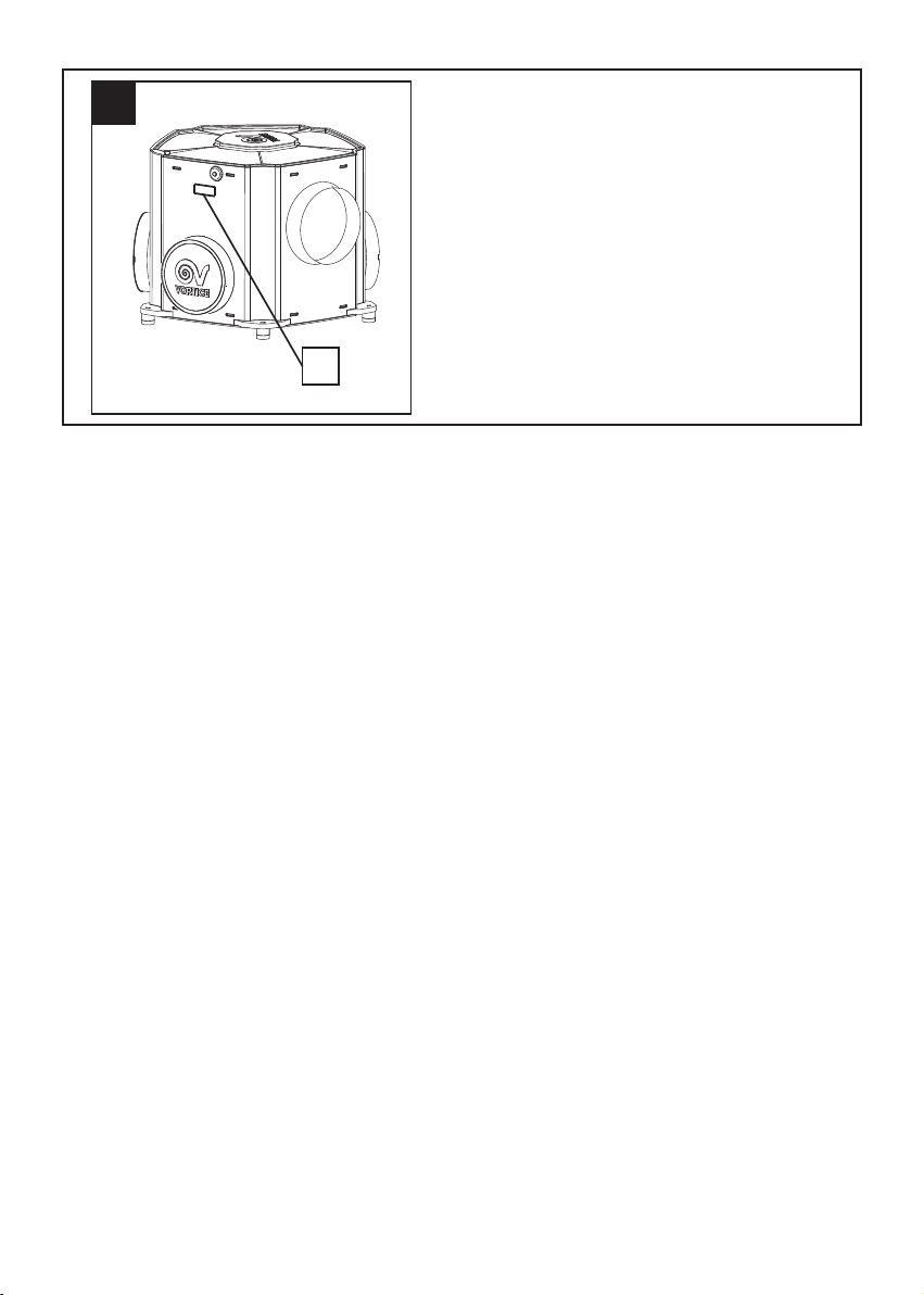
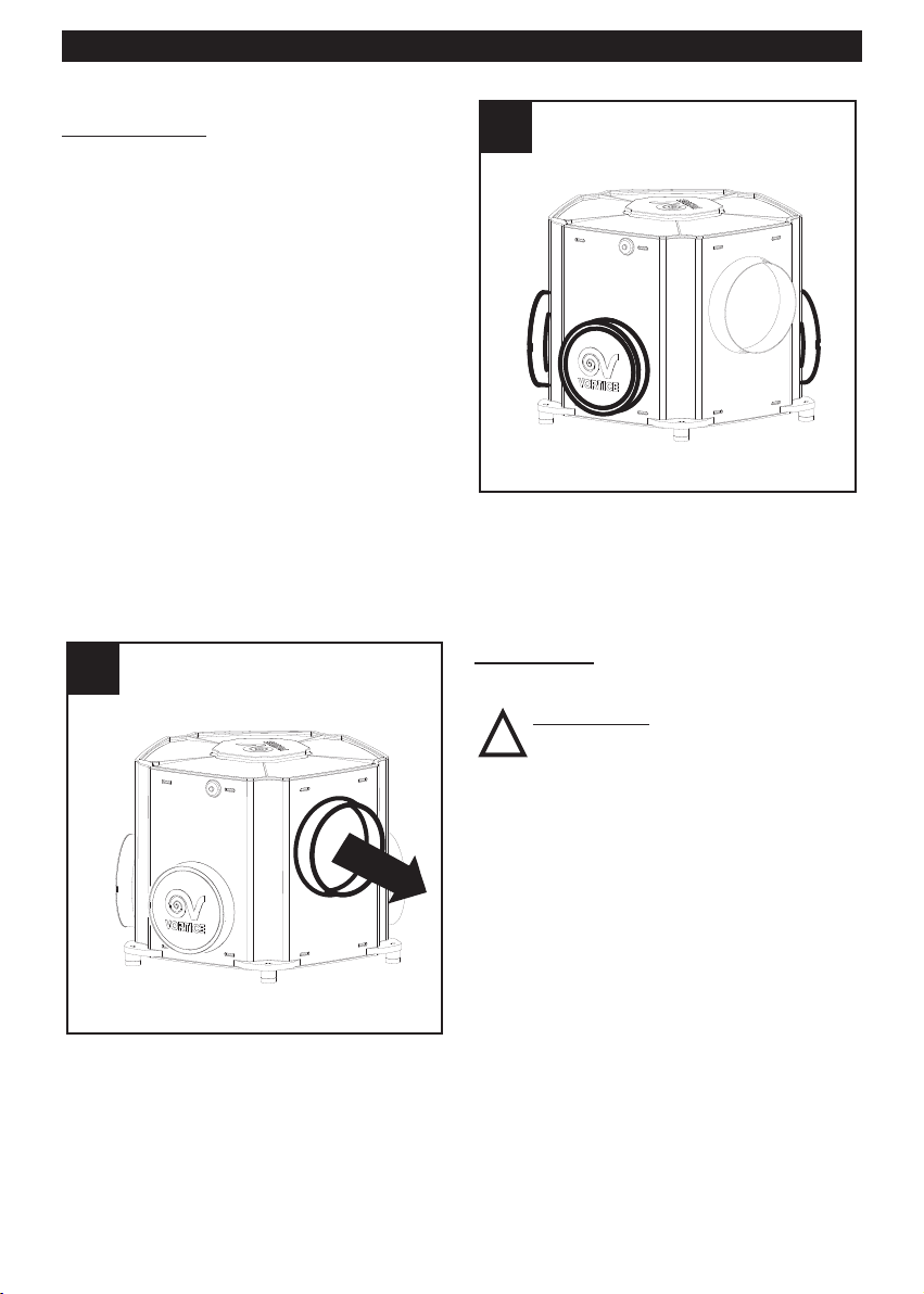
Rimozione del coperchio superiore
Svitare la vite di bloccaggio (fig. 3) ed estrarre il
coperchio agendo sulla levetta. (fig. 4).
Regolazione dei trimmer
La scheda elettronica che equipaggia l’apparecchio
della gamma Vort Leto Mev HCS è dotata di due
trimmer, “RV1” ed “RV2”, per impostare
rispettivamente i valori della velocità minima (Vmin) e
massima (Vmax); (la velocità media Vmed è la media
dei valori Vmin e Vmax precedentemente impostati).
I valori impostabili per tali velocità sono:
•V
min: 350 rpm ÷ velocità massima corrente meno
100 rpm;
•V
max: 600 ÷ 2600 rpm.
L’impostazione deve aver luogo entro 1 ora dalla
connessione dell’apparecchio alla rete, istante
corrispondente all’avvio di un timer. Decorso tale
periodo, ulteriori eventuali azioni sui trimmer non
verranno più accettate dalla scheda. Per una nuova
regolazione sarà necessario procedere alla
disconnessione e successiva riconnessione alla rete.
All’atto del riavvio l’apparecchio mantiene le
impostazioni precedentemente realizzate o le
impostazioni di default, a prescindere dalla posizione
dei trimmer, che dovranno essere portati a fine corsa,
ruotandoli in senso anti-orario, per procedere ad una
6
ITALIANO

nuova configurazione.
Prima di procedere alla regolazione i due trimmer
devono essere portati sullo “0”. In tale condizione i
valori di default sono Vmax= 600 rpm, Vmin= 350 rpm.
NOTA
Ogni 3 minuti si ha il salvataggio delle velocità correnti;
NOTA
É consigliabile regolare prima la Vmin e poi la Vmax, in
quanto al variare di Vmin, a pari posizione di “RV2”
varierà anche la Vmax;
NOTA
L’ottenimento della portata richiesta in ogni locale
asservito presuppone la contemporanea regolazione
della velocità del motore e del grado di apertura delle
bocche di aspirazione nei locali.
NOTA
Incrementare la velocità del motore porta ad un
incremento dei consumi energetici e delle emissioni
sonore.
Procedura per la regolazione delle velocità:
• aprire il contatto selezione velocità;
• regolare Vmin, da 350 a Vmax – 100 rpm (fig. 6);
• mantenere chiuso il contatto selezione velocità;
• regolare Vmax, da 600 a 2600 rpm (fig. 5);
•attendere 5 minuti per consentire all’apparecchio di
memorizzare le impostazioni;
• togliere tensione all’apparecchio;
• riattivare l’apparecchio per verificare che le
impostazioni siano state recepite.
Qualora la portata minima richiesta dalla specifica
installazione non sia conseguibile nell’intervallo di
regolazione della velocità minima, sarà necessario
33
44
55
66
7
ITALIANO

predisporre l’apparecchio affinchè la portata minima
sia ottenuta mediante la velocità media.
IMPOSTAZIONE SOGLIA UMIDITÀ RELATIVA
In fase di installazione è possibile impostare i valori di
soglia desiderati per le due sonde di umidità relativa. I
valori (60, 70, 80, 90%) sono impostabili manualmente
mediante l’utilizzo di un dipswitch. Utilizzare le possibili
combinazioni illustrate (fig. 7A e 7B).
POSIZIONAMENTO SENSORI
Procedere alla rimozione del coperchio inferiore (fig.3
e fig.4). I sensori, preinstallati a bordo macchina, sono
tenuti in posizione mediante l’utilizzo di appositi
portasonda fissato alla coclea. Qualora le esigenze
dell’impianto lo richiedano, i portasonda possono
essere spostati e riposizionati nelle bocchette di
aspirazione desiderate, sfruttando le sedi di fissaggio
ricavate sulla coclea. Sono inoltre forniti cinque
fermacavi adesivi, da sfruttarsi per il bloccaggio dei
cavi delle sonde, al fine di impedire che questi
possano entrare nel condotto di aspirazionee venire a
contatto con la girante durante le fasi di
funzionamento. Assicurarsi che i cavi delle sonde
siano ben fissati ai fermacavi prima di avviare il
prodotto.
LED DI CONTROLLO
A bordo macchina, sulla scheda elettronica, sono
previsti due led di controllo (“DL1” e “DL2”).
Il led “DL1” segnala la presenza di eventuali errori di
sistema. Può presentare i seguenti stati:
• lampeggio molto veloce: la scheda non rileva
correttamente la presenza del motore;
• lampeggio molto lento: il sistema rileva una
sovracorrente.
8
ITALIANO
DIPSWITCH
COMBINAZIONE
VALORE SOGLIA RH%
OFF-OFF-OFF-OFF
60%
OFF-ON-OFF-OFF
70%
ON-OFF-OFF-OFF
80%
ON-ON-OFF-OFF
90%
1
2
3
4
ON
OFF
1
2
3
4
ON
OFF
1
2
3
4
ON
OFF
1
2
3
4
ON
OFF
7A77A
7B7B
8A8A
8B8B
FERMACAVI

MANUTENZIONE/PULIZIA
Per verificare lo stato di pulizia dell’apparecchio,
operare come segue:
•disconnettere l’apparecchio dalla rete di
alimentazione elettrica;
• rimuovere uno o più tappi eventualmente posti in
corrispondenza delle bocche non connesse a
condotti di aspirazione, in modo tale da poter vedere
l’interno dell’apparecchio e la girante;
• verificare la presenza di polvere sulla girante: un
sottile strato di polvere non ne compromette le
prestazioni, ma se lo strato di polvere supera il
millimetro di spessore all’interno delle pale, è
opportuno procedere alla sua pulizia.
• controllare i cuscinetti del motore, facendo girare la
girante: cuscinetti in buono stato non emettono
rumori; la girante se mossa manualmente effettua
solo alcuni giri, muovendosi a scatti, quindi si arresta.
Tale comportamento, denominato “clogging”, è tipico
dei gruppi mossi da motori a magnete permanente,
come quelli che equipaggiano i Vort Leto Mev HCS;
• dopo l’eventuale pulizia riposizionare i tappi in
corrispondenza delle bocche di aspirazione;
• ricollegare l’apparecchio all’alimentazione;
Le bocchette devono essere pulite regolarmente per
assicurare la perfetta efficienza dell’impianto e la
salubre ventilazione dei locali asserviti. Assicurarsi che
le impostazioni del sistema non vengano variate. Ogni
bocchetta deve essere riposizionata esattamente in
corrispondenza dello stesso condotto da cui è stata
rimossa. Le bocchette senza filtro posso essere
rimosse dallo sbocco del condotto. La schiuma
isolante (se presente), deve essere rimossa prima di
pulire la bocchetta in acqua tiepida e liquido
detergente. Riposizionare le bocchette dopo la pulizia.
COLLEGAMENTI ELETTRICI
99
1010
9
ITALIANO

10
ITALIANO
1313 VELOCITA’ MASSIMA
L
N
N1 L2 3 4
Informazione importante per lo
smaltimento ambientalmente
compatibile
IN ALCUNI PAESI DELL'UNIONE EUROPEA
QUESTO PRODOTTO NON RICADE NEL CAMPO
DI APPLICAZIONE DELLA LEGGE NAZIONALE DI
RECEPIMENTO DELLA DIRETTIVA RAEE E
QUINDI NON È IN ESSI VIGENTE ALCUN OBBLIGO
DI RACCOLTA DIFFERENZIATA A FINE VITA.
Attenzione
Questo prodotto è conforme alla Direttiva
EU2012/19/EC.
Il simbolo del bidone barrato riportato
sull’apparecchio indica che il
prodotto, alla fine della
propria vita utile, dovendo
essere trattato
separatamente dai rifiuti
domestici, deve essere
conferito in un centro di
raccolta differenziata per
apparecchiature elettriche ed
elettroniche oppure
riconsegnato al rivenditore al momento
dell’acquisto di una nuova apparecchiatura
equivalente.
Presso i rivenditori di prodotti elettronici con superficie
di vendita di almeno 400 m2è inoltre possibile
consegnare gratuitamente, senza obbligo di acquisto,
i prodotti elettrici ed elettronici da smaltire, se di
dimensioni inferiori a 25 cm.
L’utente è responsabile del conferimento
dell’apparecchio a fine vita alle appropriate strutture di
raccolta, pena le sanzioni previste dalla vigente
legislazione sui rifiuti.
L’adeguata raccolta differenziata per l’avvio successivo
dell’apparecchio dismesso al riciclaggio, al trattamento
e allo smaltimento ambientalmente compatibile
contribuisce ad evitare possibili effetti negativi
sull’ambiente e sulla salute e favorisce il riciclo dei
materiali di cui è composto il prodotto.
Per informazioni più dettagliate inerenti i sistemi di
raccolta disponibili, rivolgersi al servizio locale di
smaltimento rifiuti o al negozio in cui è stato effettuato
l’acquisto.
I produttori e gli importatori ottemperano alla loro
responsabilità per il riciclaggio, il trattamento e lo
smaltimento ambientalmente compatibile sia
direttamente sia partecipando ad un sistema collettivo.
1212 VELOCITA’ MEDIA
L
N
N1 L2 3 4
L
N
N1 L2 3 4
1111 VELOCITA’ MINIMA

Compliance with Building Codes
The 2006 Edition of the U.K Building Regulations
Approved Document F1: Means of Ventilation (applicable
in England and Wales) details 4 clearly defined systems
of ventilation to dwellings. System 3 - Continuous
mechanical extract (MEV) is complied with by the new
VORT LETO MEV ultra-high efficiency whole house
extract ventilation system.
System 3- Continuous mechanical extract requires a
"minimum high rate" in each wet room to be achieved
(Kitchens 13 l/s and both utilities and bathrooms 8 l/s -
sanitary only 6 l/s).
The "minimum low rate" is calculated by taking the
number of bedrooms in the dwelling and applying the
l/s value from Table 1.1b (pag.26). In addition the rate
should be no less than 0.3 l/s per m_ of internal floor
area (all storey’s) plus for each additional occupant
over and above the anticipated two for the first
bedroom and one for each of the others a further 4 l/s
must be added to the extract rate. The system provides
quiet, uninterrupted extract ventilation from the dwelling
via all the wet rooms, creating a permanent air path
through the property from the “dry” habitable rooms to the
“wet” rooms.
The current Building (Scotland) Regulations refers to
continuously operating mechanical
extract ventilation in accordance with the guidance in
BRE (Building Research Establishment)
Digest 398, a paper based on the former government
department’s (and now private company)
own tests and recommendations , specifically 0.5 air
changes per hour throughout the property.
The VORT LETO MEV complies fully with the
recommendations contained within this document.
In Ireland, Technical Guidance Document (TGD) 2008
Part F: Ventilation is applicable and the Vort Leto MEV
complies fully with the recommendations contained
within this document.
With the Governments actively encouraging energy
saving and a target for all new homes to be ‘carbon zero’
by 2016, the VORT LETO MEV has been designed
‘future proof’.
The ‘Code for Sustainable Homes’ which came into force
in March 2007, details six levels of CO2emission
improvement over 2006 Building Regulations
requirements.
To achieve the three highest levels of reduction of carbon
emissions, the air leakage of the dwelling must be
improved so significantly that continuous ventilation
becomes the only appropriate method. In addition, it must
be demonstrated that the ventilation system itself
must be energy efficient. The VORT LETO MEV has been
independently tested by the Building Research
Establishment (BRE) to the appropriate SAP (1)
Appendix Q test methodology and is therefore Appendix
Q eligible.
(1) The Governments Standard Assessment Procedure
(SAP) is a method assessing the
energy performance of dwellings and SAP Appendix Q
provides an allowance for the benefits of energy-
saving appliances; products may be independently
assessed and the results uploaded to the SAP website.
Description
Comfort and energy efficiency are becoming
increasingly important factors in buildings. With this in
mind, appliances are being developed to control the
micro-climate within homes and to provide a high
degree of comfort along with energy efficiency. These
appliances silently and continuously ventilate homes
removing humidity from service areas (bathrooms,
kitchens, etc.) and creating a flow of “dry” air in “lived-
in” areas (dining areas, studies, bedrooms, etc.). The
Vort Leto Mev HCS range of centralised ventilation
systems has been specifically designed for continuous
ventilation in domestic applications, but may also be
used in some commercial applications is fitted with
brushless three-phase motors with electronically
controlled three-speed operation:
The Vort Leto Mev HCS is a modular appliance that
means maintaining and replacing parts is both quick
and easy.
The appliance can be wall or ceiling mounted. The unit
presents 5 vents: the one positioned at the top right (fig
1) is for expelling stale air; the other 4 (fig. 2) suck
humidity and stale air.
11
11
ENGLISH

When the characteristics of an installation dictate that
one or more of the extraction vents will not be used,
these vents should be sealed using the special
blanking caps provided. This will stop any leaks and
ensure that air from the areas involved is properly
extracted.
Safety
• Do not use this appliance for functions other than
those described in this booklet
• After removing the appliance from its packaging,
ensure that it is complete and undamaged. If in
doubt contact a professionally qualified electrician or
Vortice. Do not leave packaging within the reach of
children or infirm persons
• Certain fundamental rules must be observed when
using any electrical appliance, including:
-never touch electrical appliances with wet or damp
hands;
- never touch appliances while barefoot;
- never allow children or infirm persons to operate
appliances unattended
• Do not sit on or leave objects on the appliance.
• Store the appliance out of the reach of children and
infirm persons after deciding to disconnect it from
the power supply and use it no more.
• Do not use the appliance where flammable vapours
are present (spirit, insecticides, petrol, etc.).
•This appliance can be used by
children no less than 8 years of
age and by individuals with
limited physical, sensory or
mental capacities, or by
inexperienced or untrained
individuals, provided that they
are supervised or have been
instructed in safe use of the
appliance and understand the
associated risks. Children must
not play with the appliance.
Cleaning and maintenance
procedures that can be
undertaken by the user must not
be entrusted to children, unless
under supervision.
•The appliance must be installed
by a professionally qualified
electrician.
•The electrical system to which
the product is connected must
be in compliance with applicable
regulations.
• Do not make modifications of any kind to this
appliance.
• Do not expose this appliance to the weather (rain,
sun, etc.).
• Regularly inspect the appliance for visible defects.
If any faults are found, do not operate the appliance;
contact Vortice immediately.
• If the appliance does not function correctly or
develops a fault, contact Vortice immediately.
Ensure that only genuine original Vortice spares
are used for any repairs.
• Should the appliance be dropped or suffer a heavy
blow, have it checked immediately by Vortice.
• The appliance must be installed by professionally
qualified personnel.
• The electrical system to which the appliance is
connected must conform to applicable standards.
• The appliance is double insulated and therefore
does not need to be earthed.
• The electrical power supply/socket to which the
appliance is to be connected must be able to provide
the maximum electrical power required by the
appliance. If it cannot do so, arrange for a qualified
electrician to make the necessary modifications.
• A multi-pole switch must be used to install the
appliance. The gap between the switch contacts
must be no less than 3 mm.
• Switch off the system’s main switch: a) if the
appliance does not function correctly; b) before
cleaning the inside and outside of the appliance;
c) if you decide not to use the appliance for any
22
12
ENGLISH
arning:
this symbol indicates that care must
be taken to avoid injury to the user
!
Caution:
this symbol indicates that care must
be taken to avoid damaging the appliance
!

length of time.
• Maintenance/Cleaning: On a yearly basis, have
professionally qualified personnel check the level of
grime that has accumulated. If necessary, use a dry
cloth or a brush to clean the control components and
fan blades. Water should only be used to clean the
adjustment vents. Do not immerse the appliance in
water or other liquids.
• Check that the air intake section, situated towards
the outside, is clear.
• The flow of air or fumes to be carried outside must
be clean (that is free of grease, soot, chemical and
corrosive agents, and explosive or flammable
mixtures).
• The appliance must not be used to activate water
heaters, room heaters, etc. and it must not discharge
into the hot air ducts of such appliances.
• Keep the appliance’s intake and outlet grilles free to
ensure an optimum flow of air.
• Specifications for the power supply must correspond
to the electrical data on data plate A (fig.3).
•An omnipolar switch with a
contact opening distance of 3
mm or higher should be
provided for installation,
enabling complete
disconnection under overvoltage
category III conditions.
Products equipped with three-
phase wiring (T) engines
ALWAYS require connection to
380-415V (or only 400V where
required) threephase lines, or
also 220-240V (or only 230V
where required). Any kind of
modification shall be considered
as product tampering and shall
nullify the relative warranty.
Products equipped with single-
phase wiring (M) engines
ALWAYS require connection to
220-240V (or only 230V where
required) single-phase lines. Any
kind of modification shall be
considered as product
tampering and shall nullify the
relative warranty.
Operating Principles
Air is extracted from the areas involved by connecting
the Vort Leto Mev to ducting vents placed in “damp”
areas of the home. The volume of air to be extracted
is set by moving adjustable vents and depending upon
the set speed. Incoming fresh air, on the other hand,
enters via specific vents (e.g. grilles) positioned on the
walls or windows of “lived-in” areas.
Vort Leto Mev HCS is designed to ensure comfort in
the home with the least possible use of electricity.
Instructions for use
3 alternative operating speed settings available, Min,
Med, Max, started/stopped using the external switch
(diverter).
The product is also equipped with two relative humidity
sensors (pre-installed on-board the machine and to be
set on kitchen and bathroom the air inlets).
The value read by the device sensors relates to the air
suctioned into the two rooms serviced by the product
(bathroom and kitchen).
• If at least one or both probes exceed the threshold
level set by the dip switch during the installation (i.e.
60%, as factory default), the internal regulator
automatically sets the Vmax speed for the motor for 10
minutes (fixed, not settable).
• After the 10 minutes, the speed goes automatically
back to the previously set value, holding there for at
least 10 minutes, regardless of the humidity values
measured by the sensors.
Maintenance/Cleaning
Appliances in the Vort Leto Mev range do not need
scheduled maintenance work. Depending upon the
degree of pollution in the areas served by the units,
you are recommended to have the inside of the
appliances cleaned every 3/4 years (to be carried out
by a qualified technician)
(see INFORMATION FOR THE INSTALLER)
Information for the Installer
INSTALLATION
Appliances in the Vort Leto Mev HCS range are
compatible with installation in differing types of
buildings whether new or existing. They can be
mounted vertically, horizontally or inclined, in false
ceilings, on mezzanines, on ceilings, etc. The
appliance can be fixed in position by using the slots on
the base.
During the installation procedure, the instructions in
this booklet must be followed carefully and all current
legislation complied with:
NB: before carrying out any
operation it is necessary to
disconnect the power supply.
NB: in the case of speed settings
using a trimmer, precautions must
be taken against the possibility of
electric shock. Adjustment
13
ENGLISH

operations must be carried out by
qualified personnel or at a Vortice
service center
INITIAL SETTING OF SPEED
Removing the upper cover
Undo the fixing screw (fig.3) and use the lever to
remove the cover. (fig 4)
Adjusting trimmers
The circuit board fitted on the Vort Leto Mev HCS range
device is equipped with two trimmers, “RV1” and “RV2”,
for setting the minimum (Vmin) and maximum (Vmax)
values, respectively (the average Vmed speed is the
average of the previously set Vmin and Vmax values).
The values that can be set for these speeds are:
• Vmin: 350 rpm - current maximum speed minus 100
rpm
• Vmax: 600 - 2600 rpm.
Setting must occur within 1 hour of connecting the de-
vice to the mains, the instant corresponding to the start
of a timer. After this period, no further actions on the
trimmers will be accepted by the board. To adjust again,
disconnect and then re-connect to the mains. When re-
starting, the device maintains the previously-made set-
tings or the default settings, regardless of the position of
the trimmers, which must be brought to the end limit,
turning them counter-clockwise to proceed with a new
configuration.
The two trimmers must be set to “0” before regulation.
In this condition, the default values are Vmax= 600
rpm, Vmin= 350 rpm.
NOTE:
The current speeds are saved every 3 minutes.
NOTE:
It is advisable to first regulate the Vmin and then the
Vmax, as when Vmin changes, Vmax will also vary at
the same position of "RV2".
NOTE:
Achievement of the requested flow rate in each
serviced room requires simultaneous regulation of the
motor speed and of the degree of opening of the air
inlets in the rooms.
NOTE:
Increasing the speed of the motor leads to an increase
in power consumption and noise emission.
Speed regulation procedure:
• Open the speed selection contact.
• Regulate Vmin, from 350 to Vmax – 100 rpm (fig. 6).
• Keep the speed selection contact closed.
• Regulate Vmax, from 600 to 2600 rpm (fig. 5).
• Wait 5 minutes to allow the device to store the
settings.
• Cut off power to the device.
• Reactivate the device to check that the settings have
been accepted.
33
14
ENGLISH
44

If the minimum flow rate required by the specific
installation is not achievable within the minimum speed
regulation range, prepare the device so that the
minimum flow rate is obtained by the average speed.
RELATIVE HUMIDITY THRESHOLD SETTINGES
The desired threshold values for the two relative
humidity probes can be set during installation. The
values (60, 70, 80, 90%) can be set manually using a
dip switch. Use the possible combinations shows (fig.
7A and 7B).
POSITIONING SENSORS
Remove the lower cover (fig.3 and fig.4). The sensors,
pre-installed on-board the machine, are kept in
position by means of special probe holders fixed to the
scroll. If necessary for the system, the probe holders
can be moved and repositioned on the desired air
inlets, using the housings made on the scroll. Five
adhesive able ties are also supplied, to be used to lock
the cables to the probes to prevent them from entering
into the intake duct and coming into contact with the
impeller during the operating phases. Make sure that
the probe cables are well secured to the cable ties
before starting up the product.
15
ENGLISH
DIPSWITCH
COMBINAZIONE
VALORE SOGLIA RH%
OFF-OFF-OFF-OFF
60%
OFF-ON-OFF-OFF
70%
ON-OFF-OFF-OFF
80%
ON-ON-OFF-OFF
90%
1
2
3
4
ON
OFF
1
2
3
4
ON
OFF
1
2
3
4
ON
OFF
1
2
3
4
ON
OFF
7A7A
7B7B
55
66

CONTROL LEDS
Two control LEDs (“DL1” and “DL2”) are provided on
board the machine on the circuit board.
The LED “DL1” indicates the presence of any system
errors. The following states can be indicated:
• Very fast flashing: the board is not correctly detecting
the presence of the motor.
• Very slow flashing: the system detects an
overcurrent.
MAINTENANCE/CLEANING
Proceed as follows to check if the appliance needs
cleaning:
• disconnect the appliance from the mains;
•remove any blanking caps from vents that are not
connected to intake ducts so that you can see inside
the appliance and see the blades;
• check the blades for dust: A thin layer of dust will not
affect performance but, if the layer is more than 1 mm
deep, the blades should be cleaned;
•check the motor bearings by spinning the blades:
bearings in good condition make no noise; Rotating
the blades manually a few times, their movement is
jerky and they come to a stop. This behaviour is
known as “clogging” and is typical of units powered
by motors with permanent magnets like those fitted
to the Vort Leto Mev;
•on completion of the cleaning, reposition the blanking
caps where they were beforehand;
• reconnect the appliance to the mains;
Vents should be cleaned regularly to ensure that the
unit is working at its best and that the areas involved
are being well ventilated. Make sure that system
settings are not interfered with. Each vent should be
repositioned exactly as it was beforehand. Vents with
no filter can be removed from the mouth of the duct.
Any insulation foam (if present), should be removed
before cleaning the vent with warm water and liquid
detergent. Replace the vents after cleaning.
ELECTRICAL CONNECTIONS
16
ENGLISH
8B8B
CABLE TIES
8A8A
1010
99

Important information
concerning the environmentally
compatible disposal
IN CERTAIN EUROPEAN UNION COUNTRIES THIS
PRODUCT DOES NOT FALL ITHIN THE
REQUIREMENTS OF THE NATIONAL LA S
IMPLEMENTING THE EEE DIRECTIVE, AND IN
THESE COUNTRIES THE PRODUCT IS NOT
SUBJECT TO SEPARATE DISPOSAL OPERATIONS
AT THE END OF ITS ORKING LIFE.
Important
This product conforms to EU Directive EU 2012/19/EC.
This appliance bears the symbol
of the barred waste bin. This
indicates that, at the end of its
useful life, it must not be disposed
of as domestic waste, but must
be taken to a collection centre for
waste electrical and electronic
equipment, or returned to a
retailer on purchase of a
replacement.
It is the user's responsibility to dispose of this
appliance through the appropriate channels at the end
of its useful life. Failure to do so may incur the penalties
established by laws governing waste disposal.
Proper differential collection, and the subsequent
recycling, processing and environmentally compatible
disposal of waste equipment avoids unnecessary
damage to the environment and possible related
health risks, and also promotes recycling of the
materials used in the appliance.
For further information on waste collection and
disposal, contact your local waste disposal service, or
the shop from which you purchased the appliance.
Manufacturers and importers fulfil their responsibilities
for recycling, processing and environmentally
compatible disposal either directly or by participating in
collective systems.
17
ENGLISH
L
N
N1 L2 3 4
1111 MINIMUM SPEED
1212 AVERAGE SPEED
L
N
N1 L2 3 4
MAXIMUM SPEED
L
N
N1 L2 3 4
1313

Beschreibung
In den heutigen Gebäuden werden Komfort und
Energieeffizienz immer wichtiger. Zu diesem Zweck
werden Geräte entwickelt, die das Mikroklima in den
Wohnräumen kontrollieren und gleichzeitig für einen
optimalen Wohnkomfort und eine sehr gute
Energieeffizienz sorgen. Sie garantieren eine
geräuscharme und dauerhafte Belüftung der
Wohnräume, indem sie die feuchte Luft aus den
Serviceräumen (Bäder, Küchen, usw.) absaugen und
trockene Luft aus den Wohnräumen (Esszimmer,
Arbeitszimmer, Schlafzimmer, usw.) zuführen. Zu
dieser Kategorie gehören die zentralen
Lüftungsanlagen zur Dauerbelüftung von Wohn- und
Gewerberäumen der Serie Vort Leto Mev HCS.
Alle drei Geräte der Serie sind mit einem bürstenlosen
Drehstrommotor mit drei elektronisch kontrollierten
Geschwindigkeiten ausgestattet:
Vort Leto Mev überzeugt dank der modularen
Bauweise durch eine einfache Wartung und einen
problemlosen Austausch der Komponenten.
Das Gerät ist zur Wandinstallation geeignet. Die
Einheit ist mit 5 Stutzen ausgestattet: Der oben rechts
angebrachte Stutzen (Abb. 1) dient zum Abführen der
Altluft; die 4 Entlüftungsstutzen (Abb.2) sorgen für die
Austragung der verbrauchten und feuchten Luft.
Auf Grund der Anlagenkonfiguration nicht benutzte
Entlüftungsstutzen müssen mit den mitgelieferten
Deckeln verschlossen werden, um Wärmeverluste o. ä.
zu vermeiden und eine korrekte Entlüftung der
angeschlossenen Räume zu garantieren
Sicherheit
• Dieses Gerät darf nur für den Verwendungszweck
eingesetzt werden, der in der vorliegenden
Anleitung angegeben ist
• Das Gerät nach dem Auspacken auf
Transportschäden oder andere Mängel
untersuchen: im Zweifelsfall sofort einen Fachmann
oder eine autorisierte Vortice-Kundendienststelle
verständigen. Die Verpackung entsorgen und nicht
in der Reichweite von Kindern oder
unzurechnungsfähigen Personen lassen.
• Beim Gebrauch von Elektrogeräten jeder Art
müssen stets einige Grundregeln beachtet werden,
darunter im Einzelnen:
- die Geräte niemals mit nassen oder feuchten
Händen berühren;
- die Geräte niemals barfuß berühren;
- die Geräte dürfen nicht durch Kinder oder
unzurechnungsfähige Personen benutzt werden.
• Wird das Gerät vom Stromnetz getrennt und nicht
mehr benutzt, muss es an einem Ort aufbewahrt
werden, der für Kinder und unzurechnungsfähige
Personen unzugänglich ist.
• Verwenden Sie das Gerät nicht in der Nähe
entflammbarer Substanzen oder Dämpfe wie
Alkohol, Insektizide, Benzin, Sprengstoff usw.
11
22
18
DEUTSCH
Achtung:
dieses Symbol zeigt Vorsichtsmaßnahmen an
um Schäden am Bediener zu vermeiden
!

• Die An- und Absaugstutzen des Geräts stets
freihalten, damit ein optimaler Luftdurchstrom
gewährleistet wird.
•Dieses Gerät darf von Kindern
ab 8 ahren oder Personen mit
eingeschränkten körperlichen,
sensorischen oder geistigen
Fähigkeiten oder mangelnder
Erfahrung bzw. Kenntnis im
Umgang mit Elektrogeräten nur
unter der Aufsicht oder nach
gründlicher Unterweisung und
Überprüfung seitens einer für
ihre Sicherheit verantwortlichen
Person bedient werden. Kinder
dürfen nicht mit dem Gerät
spielen. Die durch den
Anwender auszuführende
Reinigung und Pflege des
Geräts darf nicht von
unbeaufsichtigten Kindern
ausgeführt werden.
•Die Elektroanlage, an die das
Produkt angeschlossen ist,
muss den geltenden Vorschriften
entsprechen.
• Keine Änderungen am Gerät anbringen.
• Das Gerät keinen Witterungseinflüssen (Regen,
Sonneneinstrahlung usw.) aussetzen.
• Überprüfen Sie den einwandfreien Zustand des
Gerätes regelmäßig. Bei festgestellten Mängeln das
Gerät nicht benutzen und sofort eine Vortice-
Kundendienststelle aufsuchen.
• Bei Betriebsstörungen und/oder defektem Gerät
sofort eine von Vortice autorisierte
Kundendienststelle aufsuchen und für eine
eventuelle Reparatur die Verwendung von Vortice-
Originalersatzteilen verlangen.
• Falls das Gerät herunterfällt oder schweren
Schlägen ausgesetzt ist, lassen Sie es umgehend in
einem vertraglich gebundenen Kundendienst-
Zentrum von Vortice überprüfen.
• Das Gerät benötigt keinen Anschluss an das
Erdungssystem, da es mit doppelter Isolierung
ausgeführt ist.
• Schließen Sie das Gerät nur an ein Stromnetz/eine
Steckdose an, wenn die Anlagenkapazität/-
aufnahme seiner maximalen Leistungen
angemessen ist. Wenden Sie sich andernfalls
unverzüglich an einen Elektrofachmann.
• Den Hauptschalter der Anlage in folgenden Fällen
ausschalten: a) Auftreten einer Betriebsstörung; b)
vor der Durchführung der Außenreinigung des
Gerätes; c) wenn das Gerät über einen längeren
Zeitraum nicht benutzt wird.
•Wartung/Reinigung: Lassen Sie durch fachlich
qualifiziertes Personal jährlich den Grad der
Verschmutzung überprüfen. Reinigen Sie bei Bedarf
die Verstellelemente und Lüfterblätter mit einem
trockenen Tuch oder einer Bürste. Nur die
Einstellbuchsen mit Wasser waschen
• Das Gerät nicht in Wasser oder andere
Flüssigkeiten tauchen.
• Überprüfen Sie, ob der Einlassabschnitt der nach
außen gerichteten Lufteinlässe frei ist.
• Der abgezogene Luftstrom muss sauber sein (d.h.
ohne fette Teilchen, Ruß, chemische oder korrosive
Substanzen oder explosive und entzündbare
Mischungen).
• Das Gerät darf nicht als Aktivator für Heizlüfter, Öfen
etc. benutzt werden. Die Abluft des Geräts darf nicht
in Warmluftleitungen derartiger Geräte geleitet
werden,
• Die Ein- und Auslassöffnungen des Gerätes dürfen
nicht abgedeckt oder versperrt werden, um einen
optimalen Luftstrom zu gewährleisten.
•Für die Installation muss ein
mehrpoliger Stecker angebracht
sein, dessen Öffnungsabstand
der Kontakte gleich oder über 3
mm ist, mit dem die vollständige
Trennung unter Bedingungen
der Überspannungskategorie III
möglich ist.
• Die Produkte mit Dreiphasen-
Motoren (T) müssen STETS an
ein 380-415V (oder, sofern
vorgesehen, nur 400V)
Dreiphasennetz angeschlossen
werden oder ggf. an 220-240V
(bzw. nur 230V, sofern
vorgesehen). ede Änderung gilt
als unsachgemäßer Zugriff auf
das Produkt und macht die
Garantie ungültig. Die Produkte
mit Einphasen-Motoren (M)
müssen STETS an ein 220-
240V (bzw. nur 230V, sofern
vorgesehen) Einphasennetz
angeschlossen werden. ede
Änderung gilt als
unsachgemäßer Zugriff auf das
Produkt und macht die Garantie
ungültig.
19
DEUTSCH
Hinweis:
dieses Symbol zeigt Vorsichtsmaßnahmen an
um Schäden am Gerät zu vermeiden
!

Funktionsweise
Die Abführung der Luft aus den angeschlossenen
Räumen erfolgt durch den Anschluss von VLM an die
in den Feuchträumen endenden Kanäle. Die Menge
der abzusaugenden Luft wird durch einstellbare
Öffnungen je nach Anlagenbeschaffenheit und den
geltenden Normen reguliert. Die Frischluft dagegen
tritt von außen durch die an den Außenwänden oder
an den Fenstern der Wohnräume (Wohnzimmer, usw.)
angebrachten Öffnungen (z. B. Gitter) ein.
Das Vort Leto Mev ist so konzipiert, dass ein optimaler
Wohnkomfort bei minimalem Energieverbrauch
garantiert wird.
Gebrauch
Die Einstellung der Betriebsgeschwindigkeit zwischen
den 3 verfügbaren Alternativen Min, Medium, Max
erfolgt über einen externen Schalter
(Wechselschalter).
Das Produkt verfügt außerdem über zwei Relativ-
Feuchtigkeitssensoren (vorinstalliert auf der Maschine
und für die Sauganschlüsse von Küche und Bad
vorgesehen).
Der von den Sensoren gemessene Wert bezieht sich
auf die Luft, die in die beiden vom Produkt bedienten
Räume (Bad und Küche) gesaugt wird.
• Wenn mindestens eine oder beide Sonden den per
DIP-Schalter eingestellten Schwellenwert
überschreiten (z.B. 60% als Werkseinstellung), stellt
die interne Steuerung automatisch die Vmax-
Drehzahl für den Motor für einen Zeitraum von 10
Minuten ein (fix, nicht einstellbar);
• Nach 10 Minuten kehrt die Geschwindigkeit auf den
zuvor eingestellten Wert zurück und bleibt für
mindestens 10 Minuten erhalten, unabhängig von
den von den Sensoren gemessenen
Feuchtigkeitswerten.
artung/Reinigung
Die Geräte der Serie Vort Leto Mev benötigen keine
regelmäßige technische Wartung; allerdings sollte das
Geräteinnere je nach Verschmutzungsgrad der
Raumluft alle 3 / 4 ahre von einem Fachmann
gereinigt werden.
Informationen für den Installateur
INSTALLATION
Die Geräte der Serie Vort Leto Mev HCS eignen sich
sowohl zur Installation in Neubauten, als auch zum
nachträglichen Einbau in bereits bestehende
Gebäude unterschiedlicher Bauart. Der Einbau ist in
vertikaler oder horizontaler Stellung, in Schräglage, in
Zwischendecken, in Hängeböden, Dachböden, usw.
möglich und der Gerätekörper kann mit Hilfe der an
der Unterseite angebrachten Schlitze befestigt
werden.
Bei der Installation immer die geltenden gesetzlichen
Bestimmungen und die Anweisungen dieser
Betriebsanleitung beachten.
Achtung: Bevor Sie einen
Vorgang ausführen, müssen Sie
die Stromversorgung
unterbrechen.
Achtung: Bei
Geschwindigkeitseinstellungen
mit einem Trimmer müssen
Vorkehrungen gegen die
Möglichkeit eines elektrischen
Schlags getroffen werden.
Anpassungen müssen von
qualifiziertem Personal oder in
einem Vortice-Servicecenter
durchgeführt werden
ERSTEN EINSTELLUNG DER GESCH INDIGKET
Entfernen der Obereb Abdeckung
Die Befestigungsschraube lösen (Abb. 3) und die
Abdeckung bei Betätigung des Verschlussriegels
herausziehen. (Abb. 4)
Trimmereinstellung
Die Elektronikkarte, welche die Vort Leto Mev HCS-
Gerätefamilie ausstattet, ist mit zwei Trimmern "RV1"
und "RV2" ausgestattet, um den minimalen (Vmin)
bzw. maximalen (Vmax) Geschwindigkeitswert
einzustellen; (die Durchschnittsgeschwindigkeit Vmed
ist der Mittelwert der zuvor eingestellten Vmin- und
Vmax-Werte).
Die Werte, die für diese Geschwindigkeiten eingestellt
werden können, sind:
• Vmin: 350 U/min ÷ maximale Drehzahl des Stroms
minus 100 U/min;
• Vmax: 600 ÷ 2600 U/min.
Die Einstellung muss innerhalb 1 Stunde nach dem
Anschluss des Geräts an das Netzwerk erfolgen, d.h.
zu dem Zeitpunkt, zu dem ein Timer gestartet wird.
Nach Ablauf dieser Frist werden alle weiteren Aktionen
an den Trimmern von der Karte nicht mehr akzeptiert.
Für eine neue Einstellung müssen Sie die Verbindung
trennen und dann wieder mit dem Netzwerk verbinden.
Beim Neustart behält das Gerät die zuvor
vorgenommenen Einstellungen oder die
Standardeinstellungen bei, unabhängig von der
Position der Trimmer, die zum Ende des Hubs gebracht
werden müssen, und dreht sie gegen den
Uhrzeigersinn, um zu einer neuen Konfiguration
überzugehen.
20
DEUTSCH
Other manuals for VORT LETO MEV HCS
1
Table of contents
Languages:
Other Vortice Ventilation Hood manuals

Vortice
Vortice VORTEX 60-I User manual

Vortice
Vortice CA MD RF User manual

Vortice
Vortice RXH/Hi Series User manual

Vortice
Vortice LINEO 100 User manual

Vortice
Vortice VORT PRESS 110 I LL User manual

Vortice
Vortice VORT-NRG User manual

Vortice
Vortice AXIAL K User manual

Vortice
Vortice PUNTO EVO ME Series User manual

Vortice
Vortice HRI MINI User manual

Vortice
Vortice HRI MINI EP User manual