Savo C-7804-S User manual

C-7804-S
C-7804-W
C-7804-S3
C-7804-W3
Instructions Manual
Käyttöohje
Bruksanvisning

2
2
INDEX
SAFETYINFORMATION......................................................................................................................................................... 3
CHARACTERISTICS.............................................................................................................................................................6
INSTALLATION......................................................................................................................................................................7
USE......................................................................................................................................................................................11
CAREANDCLEANING.........................................................................................................................................................12
SISÄLTÖ
TURVALLISUUSTIETOJA.....................................................................................................................................................14
MITAT JA OSAT .................................................................................................................................................................. 17
ASENNUS............................................................................................................................................................................ 18
KÄYTTÖ...............................................................................................................................................................................22
PUHDISTUSJAHUOLTO..................................................................................................................................................... 23
INNEHÅLL
SÄKERHETSINFORMATION................................................................................................................................................ 25
EGENSKAPER.....................................................................................................................................................................28
INSTALLATION.................................................................................................................................................................... 29
ANVÄNDING........................................................................................................................................................................ 33
NGÖRINGOCHUNDERHÅL................................................................................................................................................ 34
EN
FI
SE

EN 3
3
SAFETY INFORMATION
For your safety and correct operation of the appliance, read this manual
carefully before installation and use. Always keep these instructions
with the appliance even if you move or sell it. Users must fully know the
operation and safety features of the appliance.
The wire connection has to be done by specialized technician.
The manufacturer will not be held liable for any damages resulting from
incorrect or improper installation.
The minimum safety distance between the cooker top and the extractor
hood is 650 mm (some models can be installed at a lower height,
please refer to the paragraphs on working dimensions and installation).
If the instructions for installation for the gas hob specify a greater
distance, this must be respected.
Check that the mains voltage corresponds to that indicated on the
rating plate fixed to the inside of the hood.
Means for disconnection must be incorporated in the fixed wiring in
accordance with the wiring rules.
For Class I appliances, check that the domestic power supply
guarantees adequate earthing.
Connect the extractor to the exhaust flue through a pipe of minimum
diameter 120 mm. The route of the flue must be as short as possible.
Regulations concerning the discharge of air have to be fulfilled.
Do not connect the extractor hood to exhaust ducts carrying
combustion fumes (boilers, fireplaces, etc.).

EN 4
4
If the extractor is used in conjunction with non-electrical appliances
(e.g. gas burning appliances), a sufficient degree of aeration must be
guaranteed in the room in order to prevent the backflow of exhaust gas.
When the cooker hood is used in conjunction with appliances supplied
with energy other than electric, the negative pressurein the room must
not exceed 0,04 mbar to prevent fumes being drawn back into the room
by the cooker hood.
The air must not be discharged into a flue that is used for exhausting
fumes from appliances burning gas or other fuels.
If the supply cord is damaged, it must be replaced from the manufac-
turer or its service agent.
Connect the plug to a socket complying with current regulations, lo-
cated in an accessible place.
With regards to the technical and safety measures to be adopted for
fume discharging it is important to closely follow the regulations pro-
vided by the local authorities.
WARNING: Before installing the Hood, remove the protective films.
Use only screws and small parts in support of the hood.
WARNING: Failure to install the screws or fixing device in accordance
with these instructions may result in electrical hazards.
Do not look directly at the light through optical devices (binoculars,
magnifying glasses…).
Do not flambè under the range hood; risk of fire.
This appliance can be used by children aged from 8 years and above
and persons with reduced physical, sensory or mental capabilities or
lack of experience and knowledge if they have been given supervision
or instruction concerning use of the appliance in a safe way and under-
stand the hazards involved. Children shall not play with the appliance.
Cleaning and user maintenance shall not be made by children without
supervision.
Children should be supervised to ensure that they do not play with the
appliance.

EN 5
5
The appliance is not to be used by persons (including children) with re-
duced physical, sensory or mental capabilities, or lack of experience
and knowledge, unless they have been given supervision or instruction.
Accessible parts may become hot when used with cooking appliances.
Clean and/or replace the Filters after the specified time period (Fire
hazard). See paragraph Care and Cleaning.
There shall be adequate ventilation of the room when the range hood is
used at the same time as appliances burning gas or other fuels (not
applicable to appliances that only discharge the air back into the room).
The symbol on the product or on its packaging indicates that this
product may not be treated as household waste. Instead it shall be
handed over to the applicable collection point for the recycling of elec-
trical and electronic equipment. By ensuring this product is disposed of
correctly, you will help prevent potential negative consequences for the
environment and human health, which could otherwise be caused by
inappropriate waste handling of this product. For more detailed informa-
tion about recycling of this product, please contact your local city office,
your household waste disposal service or the shop where you pur-
chased the product.

EN 6
6
CHARACTERISTICS
Dimensions
Min.
550mm
Min.
550mm
Components
Ref. Q.ty Product components
11 Hood equipped with: Controls, Lights, Fil-
ters
31 Hood support equipped with the Exhaust
Group
71 tube in PVC
81 Directioned grid
8c 1 Air outlet reduction ø 120mm
91 Reduction flange ø 150-120 mm
11b 2 Flap
Ref. Q.ty Installation components
11 4 Small blocks ø 10
12a 4 Screws 5 x 70
12b 4 Screws M4 x 15
12e 2 Screws 2,9 x 9,5
13 4 Screws plug M4
Q.ty Documentations
1 Instruction booklet
9
8
12e
11b
13 7
12b
1
3
12a
11
8c

EN 7
7
INSTALLATION
Wall drilling and bracket fixing
When installing the hood in recycling version it has to be taken into consideration that space re-
maining between the hood and the upper limit (ceiling or self) is at least 15 cm.
On the wall, draw:
• a Vertical line up to the ceiling or upper limit, at the centre of the area in which the hood is
to be fitted;
• a Horizontal line at a minimum of 1050 mm above the Cooker Top; .
• As indicated, mark a reference point at 100 mm to the right of the vertical reference line.
• Repeat this operation on the other side, checking that the two marks are level.
• As indicated, mark a reference point at 390 mm above the horizontal reference line, and at
100 mm to the right of the vertical reference line.
• Repeat this operation on the other side, checking that the two marks are level.
• Drill at the points marked, using a ø 10 mm drill bit.
• Insert the plugs 11 into the holes.
11
12a
100 100
1050 390
1240
175
170
100 100

EN 8
8
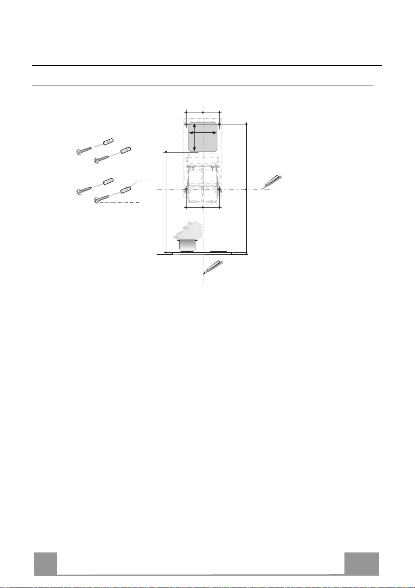
Hood support mounting
• Lean the hood support 3 against the wall making sure
that holes in the hood support correspond to those in the
wall.
• Block the hood support to the wall using 4 12a (5 x 70)
screws supplied with the hood.
• Before fastening the screws definitively make sure that
the support is well-levelled. Only after this operation
proceed with the definitive tightening of the screws.
3
12a
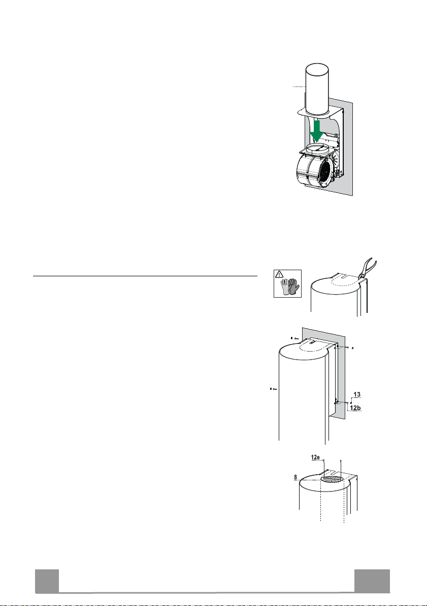
Air outlet connection in the ducting version
When installing the hood in ducting version, basing on the
installer’s choice, a rigid or a flexible pipe with a ø 150 o
120 mm is used in order to connect the hood to the air out-
let piping. The pipe connection can be made on the upper
part or on the back side of the hood.
• Insert flaps 11b on the Hood Canopy Outlet.
AIR OUTLET ON THE BACK SIDE OF THE HOOD
• When drilling the air outlet hole in the wall proceed in
accordance with the scheme in the paragraph concern-
ing the wall drilling.
• In case the connection is made with a ø 120 mm pipe
insert the reduction flange 9on the hood body outlet.
• Fix the pipe with an adequate quantity of pipe clamps.
This material is not supplied together with the hood.
• Remove the charcoal filter if present.
AIR OUTLET ON THE UPPER PART OF THE HOOD
• In case the connection of the hood to the air outlet pip-
ing is made with a ø 150 mm pipe then use a rigid or a
flexible pipe.
• In case the connection is made with a ø 120 mm pipe
insert the reduction flange 9 on the hood body outlet.
• Fix the air outlet reduction 8c to the air outlet hole of
the hood support with the screws supplied together with
the hood.
• Connect the hood to the piping with a rigid or a flexible
pipe.
• Fix the pipe with an adequate quantity of pipe clamps.
This material is not supplied together with the hood.
• Remove the charcoal filter if present.
ø 150
ø 120
9
8c

EN 9
9
RECIRCULATION VERSION AIR OUTLET
• Insert pvc pipe 7 provided onto the Hood Canopy Outlet.
7
ø 150
Hood body mounting
Ducting version
• In case the air outlet connection on the upper part of the
hood has been chosen it will be necessary to remove the
pre-cut piece.
• Lean the hood body on the support and fix it laterally
with the 4 12b screws.
• Cover the screw seats with the plugs 13 supplied with the
hood.
Recycling version
• Remove the pre-cut piece.
• Lean the hood body on the support and fix it laterally
with the 4 12b screws.
• Cover the screw seats with the plugs 13 supplied with the
hood.
• Place the directioned grid 8on the pipe and make sure
that it is correctly installed.
• Fix the directioned grid 8with the screws 12e supplied
together with the hood.
• Make sure that the charcoal filters are present.

EN 1
10
ELECTRICAL CONNECTION
• Connect the hood to the mains through a twopole
switch having a contact gap of at least 3 mm.
• Open the lighting unit by pulling on the notch.
• Remove the filters one at a time by pushing them towards the
back of the group and pulling down at the same time.
•Being sure that the connector of the feeding cable is correctly
inserted in the socket placed on the side of the fan.
• Remember to connect the two cables inside the hood. One
of the cables must be connected to the command and the
other to the lights.
• Connect the control connector Cmd. Please do not pull the ca-
ble in order to avoid the cable from detaching.
• Connect the Spotlights connector Lux to the socket provided
behind the lighting unit cover.
• Replace the filters, make sure that the handle is visible on the
outside, and the lighting unit.
Cmd
Lux

EN 1
11
L
T1
T2
T3
T4
S1
L
S1
T1 T2 T3 T4
LT3
S1
T2
T1 T4
USE
Control panel
Button Led Function
L- Turns the lights on/off at maximum strength.
T1 Fixed Turns the motor on/off at speed one.
Fixed Turns the Motor on at speed two.
T2
- Press and hold the button for approximately 3 seconds, with all the loads turned
off (Motor and Lights), to turn the Activated Charcoal Filter alarm on. The
relevant LED flashes twice to confirm.
To turn the alarm off, press the button again and hold for at least 3 seconds. The
relevant LED flashes once.
Fixed Turns the Motor on at speed three.
T3
- Press and hold the button for approximately 3 seconds, with all the loads turned
off (Motor and Lights), to perform a reset of Filter saturation alarm. The LED S1
flashes three times.
Fixed Turns the Motor on at INTENSIVE Speed.
This speed is timed to run for 6 minutes. At the end of this time, the system
returns automatically to the speed that was set before. If it is activated with the
motor turned off, the hood will switch to OFF at the end of the time.
T4
- Press and hold for 3 seconds to enable the remote control, indicated by the LED
flashing twice.
Press and hold for 3 seconds to disable the remote control, indicated by the LED
flashing just once.
Fixed Signals the Metal Grease Filter saturation alarm, indicating that it is necessary to
wash the filters. The alarm is triggered after the Hood has been in operation for
100 working hours.
S1
Flashing When this is activated, it signals the Activated Charcoal Filter saturation alarm,
indicating that the filter must be changed; the Metal Grease Filters must also be
washed. The Activated Charcoal Filter saturation alarm comes into operation after
the Hood has been working for 200 hours.

EN 1
12
CARE AND CLEANING
REMOTECONTROL (OPTIONAL)
This appliance can be commanded using a remote control, powered by
a CR2032 type 3 V battery (not supplied).
• Do not place the remote control near heat sources.
• Do not discard the batteries with normal waste, they must be put into
the specific containers.
Metal grease filters
These can be washed in the dishwasher, and need to be cleaned
whenever the S1 Led comes on or at least once every 2 months
use, or more frequently if use is particularly intensive.
CLEANING THE FILTERS
Resetting the alarm signal
• Turn the Lights and the Suction Motor off.
• Press T3 and hold for at least 3 seconds, until LED flashes
three times in confirmation.
Cleaning the Filters
• Open the lighting unit by pulling on the nocth.
• Remove the Filter, pushing it towards the back of the unit and
at the same time pulling downward.
• Wash the filter without bending it, and leave it to dry thor-
oughly before replacing (if the surface of the filter changes
colour over time, this will have absolutely no effect on its effi-
ciency).
• Replace, taking care to ensure that the handle faces forwards.
• Replace the lighting unit.

EN 1
13
Activated Charcoal Filter (Recirculation Version)
This cannot be washed or regenerated, and must be changed when led S1 starts to flash, or at
least once every 4 months. The Alarm signal, if it has been activated, only appears when the
Suction motor is turned on.
Activating the alarm signal
• In Recirculation Version Hoods, the Filter Saturation Alarm must be activated on installa-
tion or at a later date.
• Turn the Lights and the Suction Motor off.
• Press button T2 and hold it for 5 seconds until the LED flashes twice in confirmation:
CHANGING
Resetting the alarm signal
• Turn the Lights and the Suction Motor off.
• Press T3 and hold for at least 3 seconds, until LED flashes
three times in confirmation.
Changing the Filter
• Open the lighting unit by pulling on the notch provided.
• Remove the Metal Grease Filter
• Remove the saturated Activated charcoal filter, using the hooks
provided.
• Fit the new Filter, hooking it into place.
• Fit the Grease filter and the Light Unit back into place.
Lighting unit
• For replacement contact technical support ("To purchase
contact technical support").

FI 1
14
TURVALLISUUSTIETOJA
Lue tämäkäyttöopashuolellisesti ennen laitteenasentamista jakäyttöä
omanturvallisuutesija laitteenoikeantoiminnan takaamiseksi. Pidänämä
ohjeet aina laitteen lähettyvillä, niiden täytyyseuratalaitetta myös, josse
myydääntailuovutetaan kolmansilleosapuolille. On tärkeää,ettäkäyttäjät
tuntevatlaitteentoiminta- ja turvallisuusominaisuudet.
Johtojenliitännän saa tehdä vainpätevä teknikko.
Valmistajaei vastaa väärästäasennuksestatai käytöstä aiheutuneista
vahingoista.
Pienin turvallinen etäisyys keittotason ja liesituulettimen välilläon 650 mm
(jotkutmallitvoidaan asentaaalemmas,katso työ- ja asennusmittoja
koskevaakappaletta).
Joskaasukäyttöisenkeittotason asennusohjeetmääräävät,että
etäisyyden on oltava yllämainittua suurempi, ohjeita on noudatettava.
Tarkista,ettäsähköverkon jännitevastaaliesituulettimensisällä olevan
arvokilventietoja.
Erotuskytkimetonasennettava kiinteään järjestelmään
kaapelointijärjestelmiäkoskevienmääräysten mukaisesti.
LuokanIlaitteita varten on tarkistettava,että kodin sähköverkossaon
sopivamaadoitus.
Liitäliesituuletinsavuhormiin putkella,jonkaläpimitta on vähintään120
mm.Savunpoistoreitin onoltavamahdollisimman lyhyt.
Kaikkiailmanpoistoa koskevia määräyksiäonnoudatettava.
Äläliitäliesituuletinta savukanaviin,joiden kautta poistetaan
palamishöyryjä (esimerkiksi lämmityskattilat,takatjne.).

FI 1
15
Jos liesituuletinta käytetään yhdessä muiden kuin sähkölaitteiden
(esimerkiksi kaasulaitteiden) kanssa, on pystyttävä takaamaan riittävä
huoneen tuuletus poistokaasujen paluuvirtauksen estämiseksi. Kun
liesituuletinta käytetään yhdessä muiden kuin sähkölaitteiden kanssa,
huoneen negatiivinen paine ei saa ylittää 0,04 mbar, jotta liesituuletin ei
palautahöyryjähuoneeseen.
Ilmaa ei saa poistaa sellaisen putken kautta, jota käytetään kaasulla tai
muillapolttoaineillatoimivien laitteiden savun imemiseen.
Jos virtajohto vahingoittuu, sen saa vaihtaa vain valmistaja tai
huoltopalvelunteknikko.
Kytke pistoke voimassa olevien määräysten mukaiseen ja saavutettavissa
olevaanpistorasiaan.
Savunpoistoa koskevien teknisten ja turvallisuuteen liittyvien toimenpiteiden
suhteen on noudatettava tarkkaan paikallisten viranomaisten antamia
määräyksiä.
VAROITUS: Poistasuojakalvotennen liesituulettimen asentamista.
Käytävainliesituulettimelle sopivia ruuvejajakiinnitysosia.
VAROITUS: Jos ruuveja ja kiinnitysosia ei asenneta näiden ohjeiden
mukaisesti,voiaiheutua sähköiskuvaara.
Äläkatsosuoraan optisilla välineillä(kiikari, suurennuslasi….).
Äläliekitäliesituulettimenalla:se voi aiheuttaatulipalon.
Yli 8-vuotiaat lapset ja psyykkisesti, fyysisesti tai sensorisesti rajoitteiset
henkilöt tai kokemattomat ja taitamattomat henkilöt saavat käyttää tätä
laitetta vain, jos heitä valvotaan ja heille on annettu tiedot laitteen
turvallisesta käytöstä ja siihen liittyvistä vaaroista. Varmista, etteivät lapset
pääse leikkimään laitteella. Lapset eivätsaa tehdä käyttäjän puhdistus- ja
huoltotoimenpiteitäilman valvontaa.
Valvolapsiaja varmista, etteiväthe pääse leikkimäänlaitteella.

FI 1
16
Tätälaitettaeivät saa käyttäähenkilöt(lapset mukaan lukien),joiden
mielen,ruumiintai aistien terveys onheikentynyt tai joillaei ole riittävää
kokemustajatietoa, elleiheitävalvota tai olevalmennettu.
Kosketettavissaolevat osat voivattullahyvinkuumiksi keittolaitteiden
käytönaikana.
Puhdistaja/taivaihda suodattimet määrätyn ajankuluttua(tulipalovaara).
KatsokappalettaHuolto japuhdistus.
Tilassatäytyyolla asianmukainentuuletuskunliesituuletinta käytetään
samanaikaisesti kaasulla tai muilla polttoaineilla toimivien laitteiden
kanssa(eikoske laitteita, jotkapoistavattilaan vainilmaa).
Merkki tuotteessataisen pakkauksessa osoittaa,ettätuotetta ei saa
hävittäätavallisenkotitalousjätteen mukana.Tuotetäytyy toimittaa
asianmukaiseensähköistenja elektronisten osien keräyskeskukseen.
Varmistamalla,ettätuote hävitetään oikealla tavalla, on mahdollistaauttaa
välttämäänympäristöäja henkilöiden terveyttäuhkaaviahaittavaikutuksia,
joitavoisyntyä vääränlaisesta hävittämisestä.Lisätietojatuotteen
kierrättämisestäsaat paikallisilta viranomaisilta,paikallisestajätehuollosta
tailiikkeestä,josta tuote onostettu.

FI 1
17
MITAT JA OSAT
Mitat
Min.
550mm
Min.
550mm
Osat
Nro. Määrä Laitteen osa
1 1 Tuuletin (ohjauspaneeli, valaistus, suo-
timet)
31 Tuulettimen tukiosa (imuyksikkö)
71 PVC-putki
81 Ilmansuuntausritilä
8c 1 Ilmanpoistoputken muhvi (ø 120 mm)
91 Supistuslaippa (ø 150-120 mm)
11b 2 Läppä
Nro. Määrä Asennusosat
11 4 Tappi ø 10
12a 4 Ruuvi 5 x 70
12b 4 Ruuvi M4 x 15
12e 2 Ruuvi 2,9 x 9,5
13 4 Ruuvinpäällisnapit M4
Määrä Kirjallinen materiaali
1 Käyttöohjeet
9
8
12e
11b
13 7
12b
1
3
12a
11
8c

FI 1
18
ASENNUS
Seinän poraus
On suositeltavaa, että asennustoimenpiteitä on suorittamassa ainakin kaksi henkilöä, koska
tehtävät ovat monimutkaisia.
Jos liesituuletin asennetaan suodatinversiona, on otettava huomioon, että liesituulettimen ylä-
puolelle, ylärajan (katon tai hyllyn) ja laitteen väliin, täytyy jäädä ainakin 15 cm tilaa.
Merkitse seinälle:
• pystysuora viiva kattoon tai ylärajaan saakka liesituulettimen asennusalueen keskikohdalle.
• vaakasuora viiva: vähintään 1050 mm keittotason yläpuolelle.
• Merkitse kuten kuvassa viitepiste 100 mm pystysuorasta viitelinjasta.
• Toista toimenpide toiselle puolelle ja tarkista, että ne ovat samalla tasolla.
• Merkitse viitepiste 390 mm vaakasuoran viitelinjan yläpuolelle ja 100 mm oikealle pys-
tysuorasta viitelinjasta.
• Toista toimenpide toiselle puolelle.
• Poraa merkittyihin kohtiin reiät ø 10 mm.
• Laita tulpat 11 aukkoihin.
11
12a
100 100
1050 390
1240
175
170
100 100

FI 1
19
Tuulettimen tukiosan asennus
• Aseta tuulettimen tukiosa 3 seinää vasten. Kohdista tu-
kiosan reiät seinään porattuihin reikiin.
• Kiinnitä tukiosa seinään neljällä mukana tulevalla ruu-
villa 12a (5 x 70).
• Ennen lopullista ruuvien kiristystä vaaita tukiosa. Kiris-
tä ruuvit.
3
12a
Poistoilmaversiona toimivan tuulettimen liitos
Yhdistä tuuletin ilman ulosmenoaukkoon asentajan valit-
semalla joko jäykällä tai taipuisalla ø 120-150 mm:n put-
kella.
Putki voidaan johtaa ulos joko tuulettimen ylä- tai taka-
puolelta.
• Aseta läpät 11b liesituulettimen rungon ulostuloon.
LIITOS TUULETTIMEN TAKAA
• Ilman poistoaukkoa tehdessäsi seuraa Seinän poraus
-kappaleen piirrosta.
• Sovita supistusmuhvi 9 tuulettimen ilman ulostuloauk-
koon, mikäli käytät ø120 mm:n putkea.
• Käytä putken kiinnitykseen tarpeellinen määrä putken
kiinnitysosia. Tämä materiaali ei tule tuulettimen mu-
kana.
• Poista mahdolliset aktiivihiilisuotimet.
LIITOS TUULETTIMEN YLÄPUOLELTA
• Mikäli käytät ø 150 mm:n putkea, yhdistä tuuletin ilman
ulosmenoaukkoon joko jäykällä tai taipuisalla putkella.
• Sovita supistusmuhvi 9 tuulettimen ilman ulostuloauk-
koon, mikäli käytät ø120 mm:n putkea.
• Kierrä supistusmuhvi 8c tuulettimen ilman ulostuloauk-
koon mukana tulevilla ruuveilla.
• Yhdistä tuuletin ilman ulosmenoaukkoon joko jäykällä
tai taipuisalla putkella.
• Käytä putken kiinnitykseen tarpeellinen määrä putken
kiinnitysosia. Tämä materiaali ei tule tuulettimen mu-
kana.
• Poista mahdolliset aktiivihiilisuotimet.
ø 150
ø 120
9
8c

FI 2
20
ILMAN ULOSTULO KIERTOILMAVERSIOSSA
• Asenna mukana tuleva muoviputki 7 tuulettimen ilman
ulostuloaukkoon.
7
ø 150
Tuulettimen asennus
Poistoilmaversio
• Mikäli ilman ulostulo tuulettimesta tapahtuu sen ylä-
puolelta, on irrotettava osa ulostuloaukon päältä poistet-
tava ennen tuulettimen asennusta.
• Aseta tuuletin tukiosaan. Kiinnitä se sivuilta neljällä
ruuvilla 12b.
• Aseta mukana tulevat ruuvinpäällisnapit 13 ruuveihin.
Kiertoilmaversio
• Poista irrotettava osa ulostuloaukon päältä .
• Aseta tuuletin tukiosaan. Kiinnitä se sivuilta neljällä
ruuvilla 12b.
• Aseta mukana tulevat ruuvinpäällisnapit 13 ruuveihin.
• Aseta ilmansuuntausritilä 8putkeen. Tarkista sen vir-
heetön asennus.
• Kiinnitä ilmansuuntausritilä 8 mukana tulevilla ruuveil-
la 12.
• Varmista, että aktiivihiilisuotimet ovat paikoillaan.
Other manuals for C-7804-S
1
This manual suits for next models
3
Table of contents
Languages:
Other Savo Ventilation Hood manuals
Popular Ventilation Hood manuals by other brands

Siemens
Siemens LD97DBM60B instruction manual

KitchenAid
KitchenAid KWCU405S Product dimensions

Fagor
Fagor 6CFT-90V Operation manual

Miele
Miele DA252 installation instructions

Tricity Bendix
Tricity Bendix Visor CH 520 Operating and installation instructions

ELICA
ELICA Scanno Use, care and installation guide