Votronic VAC 1215/15 DUO User manual

Installation and Operating Manual
Automatic Charger VAC 1215/15 DUO ( I=12V/15A und II=12V/15A ) No. 0626
Automatic Charger VAC 1215/30 DUO ( I=12V/15A und II=12V/30A ) No. 0627
Automatic Charger VAC 1220/20 DUO ( I=12V/20A und II=12V/20A ) No. 0629
Automatic Charger VAC 1220/30 DUO ( I=12V/20A und II=12V/30A ) No. 0631
Automatic Charger VAC 1215/40 DUO ( I=12V/15A und II=12V/40A ) No. 0636
Automatic Charger VAC 1220/40 DUO ( I=12V/20A und II=12V/40A ) No. 0634
Automatic Charger VAC 1230/30 DUO ( I=12V/30A und II=12V/30A ) No. 0642
Automatic Charger VAC 1230/40 DUO ( I=12V/30A und II=12V/40A ) No. 0644
All-automatic dual charger with 2 completely independent battery circuits for ambulance cars,
intervention vehicles and special purpose vehicles.
If not connected to the battery the units will not supply any voltage (protection against
reverse battery, safety relay, minimum battery voltage 1.0 V)!
Please read the mounting instructions and operating manual including the safety
regulations completely prior to starting connection and start-up.
The description is identical for both chargers.
VOTRONIC dual chargers of series “VAC DUO” distinguish by their compact design, low weight (high-frequency
switching power supply, Switch Mode Technology), as well as full charging capacity - even in case of large
deviations in the power supply (low voltage/overvoltage, sine curve, frequency).
The intelligent microprocessor charging control with characteristic lines of charging „IU1oU2“ and dynamic
charging time calculation ensures automatic, quick and gentle full charging, as well as subsequent 100 % trickle
charge of the connected batteries from any initial charging state. At the same time, simultaneous supply of 12 V
consumers, which are connected in parallel, is ensured or charging of very large batteries (depending on case of
application).
Operating Instructions:
All-automatic Continuous Operation: The charger may be connected continuously to the batteries, thus
keeping the full charge. Battery discharge in case of power failure is avoided (integrated safety relays).
The charging voltage being free from peaks is controlled in such a way, that any overcharging of the batteries
is excluded.
Parallel and Floating Operation: In case of simultaneous current consumption by consumers, charging of the
battery is continued or the charge will be conserved fully. Calculation and control of the adaptation of the
charging time is effected automatically by the charger. Sensitive consumers are protected by overvoltage
protection at any charging state.
Unattended Charging: Multiple protection against overload, overheating, overvoltage, short circuit, reverse
battery, excess temperature of the battery, incorrect behaviour and back discharge of battery by electronically
controlled gradual reduction down to complete separation of charger and battery by integrated safety relays.
Temperature Compensation: Automatic adaptation of the characteristic line of charging to the battery
temperature.
Integrated On-board Mains Suppression Filter: Unproblematic parallel operation of solar systems, dynamos,
generators etc.
Charging Cable Compensation: Automatic compensation of voltage losses on the charging cables.
Measurement of the voltage is to be effected at the battery and never at the charger (losses at the charging
cable).
Battery regeneration in case of extended stop periods: twice a week to avoid harmful acid accumulation.
Port +86 for motor lock while the vehicle is still connected to mains
Interruption or restart of the charging process: Due to power failure or unit switch OFF.
In case of frequent interruptions, particularly before reaching the full charge ("Battery Full" is lighting
permanently), a complete charging cycle of 24 hours of the battery should be executed more often
(compensation charging).

- 2 -
Lifetime of the battery:
Keep batteries cool; choose an appropriate location for installation.
Open acid batteries („maintenance-free according to EN / DIN“): Check the acid level
periodically!
Batteries being totally discharged should be recharged immediately, partially discharged
batteries should be recharged fully as soon as possible to avoid sulphation!
Store only fully charged batteries and recharge them periodically, particularly in case of older,
used batteries and in case of higher temperatures! If the grade of sulphation is not too intensive,
the battery can recover part of the battery capacity after several charging/discharging cycles.
Safety Regulations:
Appropriate Application:
The battery charger has been designed according to the valid safety regulations.
Appropriate application is restricted to:
1. Charging of lead-acid, lead-gel or lead-AGM batteries of the indicated nominal voltage and
simultaneous supply of the consumers being connected to these batteries in fixed installed systems
with the indicated battery capacities and charging programs.
2. Connection to a fused shockproof socket (6-16 A) being protected by a fault current breaker (FI) with
a nominal residual current of 30 mA.
3. Connection in consideration of the indicated cable cross sections at the charging ports.
4. Technically faultless condition.
5. Installation in a well-ventilated room, protected from rain, humidity, dust, aggressive battery gas, as
well as in an environment being free from condensation water.
Never use the unit at locations where the risk of gas or dust explosion exists!
Open-air operation of the unit is not allowed.
Cables are always to be laid in such a way that damage is excluded. Observe to fasten them tightly.
Never lay 12 V cables and 230 V cables into the same cable conduit (empty conduit).
Check live cables or leads periodically for insulation faults, points of break or loosened connections.
Occurring defects must be remedied immediately.
The unit is to be disconnected from any connection prior to execution of electrically welding or work on the
electric system.
If the non-commercial end-user is not able to recognize the characteristic values being valid for a unit or the
regulations to be observed, a specialist is always to be consulted.
The user/buyer is obliged to observe any construction and safety regulations.
The unit does not contain any parts, which can be replaced by the user. Even after withdrawal of the
mains plug, the unit may be extremely live for an extended period (particularly in case of failure).
Keep children away from the charger and the batteries.
Observe the safety regulations of the battery manufacturer.
Deaerate the battery room.
Non-observance may result in injury or material damage.
The warranty period is 24 months from the purchase date (against presentation of the sales slip or invoice).
The warranty will be void in case of any inappropriate utilisation of the unit, if it is used beyond the
technical specification, in case of improper operation or external intervention. We do not assume any
liability for any damage resulting hereof. The liability exclusion is extended to any service being executed by
third, which has not been ordered by us in writing. Service is to be effected exclusively by VOTRONIC
Lauterbach.

- 3 -
Option: Remote Display:
If the charger has been installed at a difficultly accessible location, the Remote
Display S for Automatic Charger "DUO" (Order No. 2078) can be used for
remote control of the charging processes (plug-and-go connection cable of 5 m
length is included in the delivery scope).
Connection:
Just insert the plug of the remote indicator into the tip jack "Remote Control" of
the charger.
Option: Remote Indicator IP67
Order No. 2081, plug-and-go connection cable, 5 m length, included in the
delivery scope.
The green light-emitting diode indicates the readiness for operation of the
charger and the mains power supply.
The remote indicator can be installed at any desired location via a bore hole,
8 mm. It can be installed at a well visible location in the inside area (for
instance in the dash board), as well as outside, such as near the driver’s
door. The delivered packing washer allows front installation with high
tightness IP67.
Connection:
Just insert the plug of the remote indicator into the tip jack "Remote Control" of
the charger.
Option: Battery Status Display IP67
Order No. 2082, Indicator with connection cable 2 m lenght to the electronic
device, adhesive label for indicator, electronic device, connection cable 5 m
length to the charger, manual
The tricoloured light-emitting diode shows the charging status of the battery
and charger and indicates the readiness of the power/electricity supply. The
remote indicator can be installed at any location by means of a bore hole, 18
mm. It can be installed at a well visible location in the inside area (for
instance in the dash board), as well as outside, such as near the driver's
door. Additional conglutination of the indicator guarantees high tightness
IP67.
Connection:
Just insert the plug of the remote indicator into the tip jack "Remote Control" of
the charger.

- 4 -
Connection:
The plug-in terminals (TT, TT etc.) on the unit's front panel can be withdrawn for connection of the cables!
Observe the cross sections and lengths of the cables, and observe the polarity.
Note: If units are equipped with charging parts of different capacities (e. g. VAC 1215/30 DUO):
Charging Part I = 12 V / 15 A (to be used for the smaller Starter Battery of the vehicle).
Charging Part II = 12 V / 30 A (to be used for the larger Main Battery).

- 5 -
Installation of the Unit:
The charger can be installed near the batteries (short charging cables) at any location being clean and being
protected from humidity and dust.
Despite the charger's high efficiency, heat is produced, which is brought out of the casing by means of the built-in
fan. Ensure sufficient ventilation in the environment of the unit, so that the heat can be carried-off to ensure full
charging capacity. Non-observation will result in gradual reduction (reduced charging capacity).
Protect the unit from aggressive battery gas.
Any position can be chosen for installation, but the vent holes of the casing should never be covered (minimum
distance 10 cm).
Ensure a solid and vibration reducing installation using rubber bushings on an even and hard mounting surface.
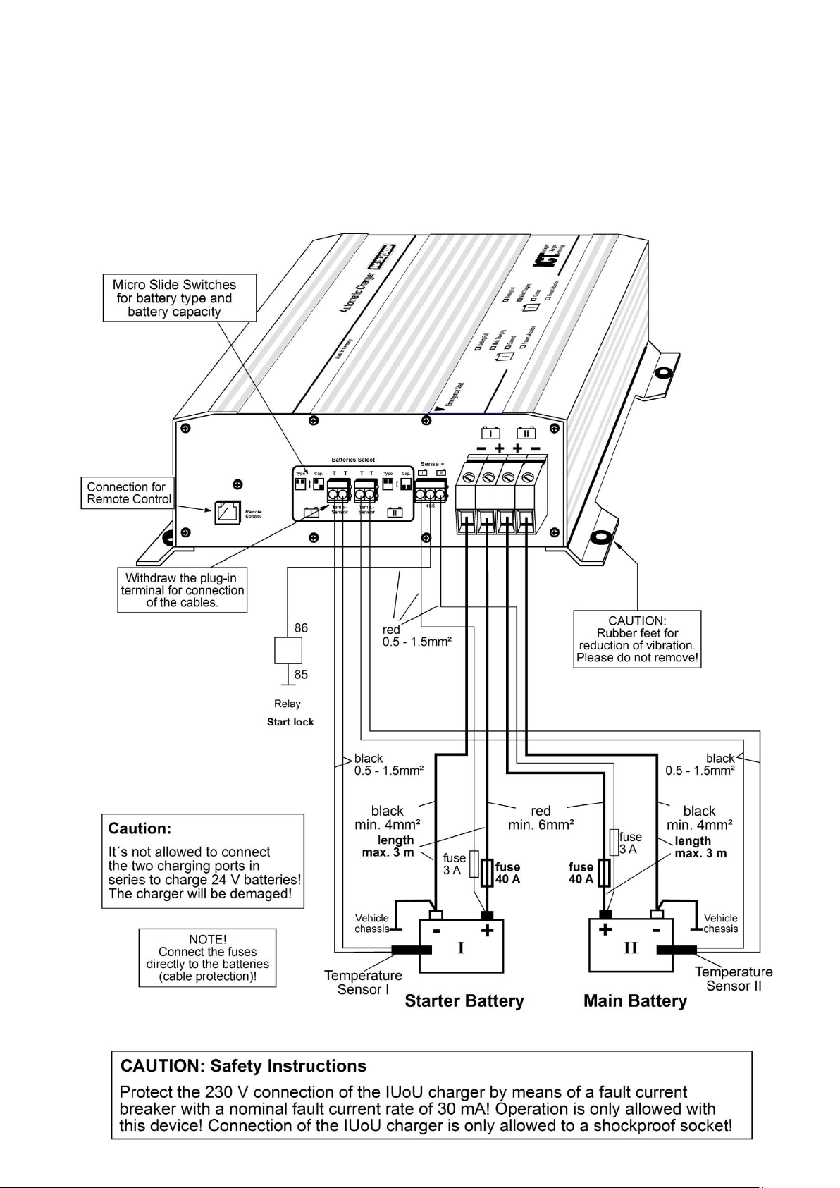
Temperature Sensors (Terminals „T T“ I and Terminals „T T“ II ):
The temperature sensors control the battery temperature and the temperature-dependent charging correction.
(Characteristic lines, see also "Temperature Compensation" in this manual.)
Connect the sensor to the corresponding terminals „T T“ of the unit (any polarity).
Never mix up the batteries (I, II)! Absolutely observe the connection plan!
Sensor Installation:
The thermal contact of sensor and battery (inside temperature) should be well. Thus, it should be screwed down
to the negative pole of the battery. It is also possible to fasten it at the sidewall centre of the battery casing.
Ensure that the installation place is not influenced by any source of heat (motor unit, exhaust, heater etc.).
Temperature Compensation:
The temperature-dependent charging voltage of the battery will be adapted automatically to the battery
temperature.
For this, the supplied temperature sensor measures the battery temperature. In case of low temperatures (winter
operation), the charging voltage will be increased in order to improve and accelerate full charging of the weak
battery. Sensitive consumers are protected by a limitation of the voltage in case of very low outside temperatures.
In case of summery temperatures, the charging voltage is reduced to minimize the load (gassing) of the battery
and to extend the lifetime of gas-tight batteries.
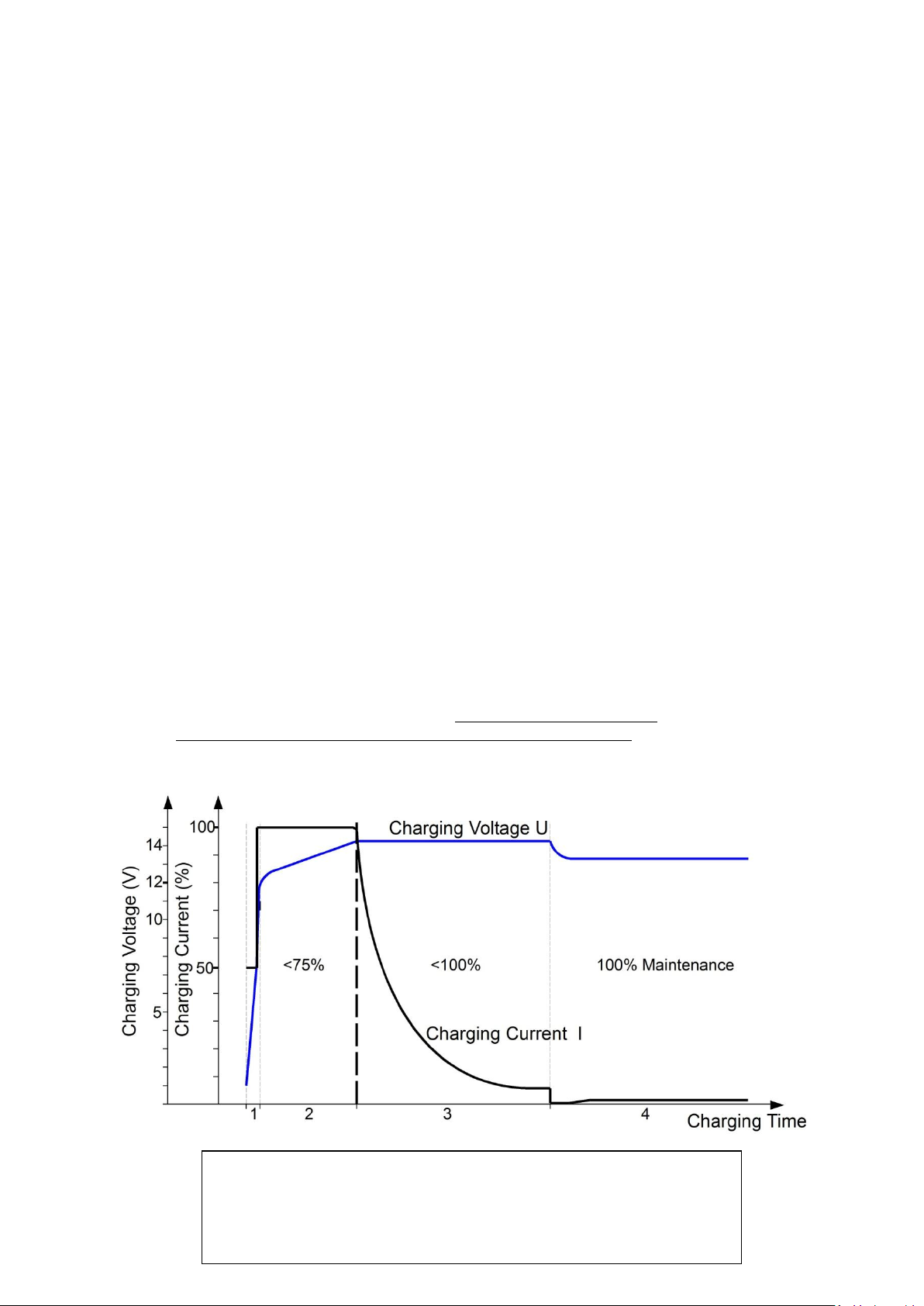
Battery Protection (also refer to Characteristic Lines “Charging Voltage Rates and Temperature
Compensation”):
In case of high battery temperatures (depending on type: 54 °C or 58 °C), the charging current will be reduced to
50 % for reasons of safety. If the battery temperature still continues to rise, a complete disconnection will be
effected by the safety relays, as soon as the temperature is exceeded by some °C, the LED „Main Charging“ will be
flashing, but any charging data being recorded hitherto will be kept in memory. Automatic charging will be
resumed as soon as the temperature drops below the above mentioned temperature values. If the battery
temperature drops below -40 °C, the charging process will also be blocked.
The charger recognizes automatically a missing sensor, cable break or short-circuit of the sensor lines,
as well as unreasonable measuring values. In that case, it will switch to the usual charging voltage rates
of 20 °C to 25 °C being recommended by the battery manufacturers.
Option: Battery Voltage Sensor Lines (Terminals „Sense“):
Particularly in case of powerful chargers being equipped with long charging cables, it is recommendable to
measure the battery voltage via a "sensor line" directly at the battery. This allows precise observation of the
charging voltage rates.
Never mix up the batteries (I, II)! Absolutely observe the connection plan!
If several batteries are connected in parallel to a battery system, the „Sense“ line has to be connected to one of
the + poles being connected to each other.
The charger will automatically recognize and evaluate the sensor line(s).
If the sensor line is not installed or in case of a cable break or fuse failures, it will be switched to normal
operation with charging cable compensation (calculated compensation of the voltage losses on the
charging cables).
Option: Vehicle Motor Lock (Terminal "+86"):
If the motor should be started by mistake while the vehicle is still connected to mains, this unit output and a
connected external relay (12 V, max. 0.4 A) in the start circuit can be used to prevent the motor start.
The Terminal "+86" supplies voltage as long as the charger is connected to mains and switched on.

- 6 -
Start-up: How to select the charging programs (separately for I and II)!
The unit front of each charging part (I and II), is equipped with 2 double slide switches for adaptation to the
connected batteries, which can be pushed to the desired position by means of a small screwdriver.
1.) How to set the battery type (design) using the switch „Type“:
Battery
Type
Selector
Switch
"Type"
If not being specified divergently by the battery manufacturer, the suitable charging
program for the battery type (design, technology) can be determined by means of the
following description and the technical data (voltage rates U1 and U2, nominal
temperature and dwell times U1).
Note: The possible parallel/floating operation with consumers being connected to the
battery is also automatically considered by all charging programs.
„ Gel “: Charging Program for Lead Gel/Dryfit Batteries, Characteristic Line IU1oU2:
Adapted to closed, gas-tight Gel batteries with determined electrolytes, which are generally
requiring a higher charging voltage level and longer dwell times U1 to achieve short charging
times with particularly high capacity storage and to avoid total discharge, such as EXIDE,
Sonnenschein dryfit- Start, Dryfit-Sport-Line, DETA Gel Battery Funline, Bosch AS Gel Batteries
Va/Z, AS Gel Drive Batteries, AS Gel Lighting Batteries.
If not being specified divergently by the battery manufacturer, also recommended for batteries in
round cell technology, such as EXIDE MAXXIMA (DC) as well as AGM batteries with 14.4 V.
EXIDE, DETA, VARTA Characteristic Line Gel IU1oU2:
U1 Main/Full Charging: 14.40 V 20° C 8-12 h
U2 Full/Trickle/Storage Charging: 13.80 V 20° C Continuous
„ AGM “: Charging Program for Lead, AGM/Fleece Batteries:
Adapted to closed, gas-tight AGM (absorbed glass mat) batteries and batteries in lead-fleece
technology requiring a particularly high level U1 for full charging.
ATTENTION: It is highly recommended to check the specification sheet of the battery concerning
the high charging voltage U1.
Unsuitable batteries might age prematurely due to loss of electrolyte!
Some manufacturers of AGM / fleece batteries are also prescribing a "gel" or "acid" charging
program with a charging voltage of 14.4 V for charging!
In this case, please set "Gel" (14.4 V / 13.8 V) or "DIN" (14.4 V / 13.4 V).
Characteristic Line AGM- / Fleece IU1oU2:
U1 Main/Full Charging: 14.70 V (!) 20 °C 3-6 h
U2 Full/Trickle/Storage Charging: 13.50 V 20° C Continuous
„DIN “: Charging Program for Lead, Acid/Lead-acid Batteries:
Usual characteristic line DIN for charging and trickle charging of open and closed lead storage
batteries with removable cell plugs and possibility of acid level control and acid level correction
(maintenance). Allows short charging times with high level U1, high charging factor and high acid
mixing, even during stationary application (acid accumulation) of "wet" drive, lighting, solar and
heavy duty batteries. Also suitable for recently developed batteries (low-antimonous, batteries
with silver-alloy, calcium/calcium or similar) and batteries with low and very low water
consumption.
Standard characteristic line according to DIN 57 510 / VDE 0510 IU1oU2:
U1 Main/Full Charging: 14.40 V 22° C 2-6 h
U2 Full/Trickle/Storage Charging: 13.40 V 22° C Continuous
„ MOTOR “: Charging Program for Lead, Acid/Lead-acid Batteries:
Characteristic line similar to dynamo/generator for (mobile) application (acid accumulation) with
particularly low maintenance (battery gassing). Charging and trickle charging of starter batteries
in intervention vehicles, in conformity with the Standard Committee Fire Protection (FNFW).
Permanent readiness for use, even with additionally connected consumers. For conventional,
standard starter batteries, starter batteries being "absolutely maintenance-free", "maintenance-
free according to EN", "maintenance-free according to DIN", "maintenance-free", "low-
maintenance".
Characteristic Line Starter IU1oU2:
U1 Main/Full Charging: 14.10 V 25° C 2.5-6 h
U2 Full/Trickle/Storage Charging: 13.38 V 25° C Continuous

- 7 -
2.) How to set the battery capacity (Ah) using the switches „Cap.“
(separately for I and II)! :
Battery
Capacity
Selector
Switch
„Cap.“
Charging Part I or II
12 V / 15 A
Charging Part I or II
12 V / 20 A
Charging Part I or II
12 V / 30 A
Charging Part II
12 V / 40 A
Charging
Phase I
Safety Timer
max.:
h
Battery
Capacity
Ah
Charging
Current
A
Battery
Capacity
Ah
Charging
Current
A
Battery
Capacity
Ah
Charging
Current
A
Battery
Capacity
Ah
Charging
Current
A
36-48
12
50-68
17
75-100
25
90-130
33
5.2
48-75
15
68-100
20
100-150
30
130-200
40
7
75-110
15
100-145
20
150-220
30
200-300
40
10
110-170
15
145-230
20
220-350
30
300-480
40
14-18
Note: In case of additional current consumption by connected consumers, the switches „Cap.“
should be set by 1 step higher.
Further actions or maintenance of the unit are not required.
Note: Several Batteries at One Charging Port:
According to the battery manufacturers, permanent parallel operation is admissible in case of two or several
batteries of the same voltage, type, capacity, as well as of the same age (history) in cross connection.
The total capacity (total Ah) should be set correspondingly using the selector switch „Cap.“.
Mains Switch (Unit Rear):
Set the mains switch to position „O“ (OFF) prior to any connection task. The unit is switched-on by position „I“.
Indicator Lamps (Each Charging Port):
„Battery Full“ (Battery fully charged, green):
If it is lighting: Battery (batteries) has (have) been charged to 100 %, trickle charging U2, finished.
If it is flashing: Main charging process is effected in the charging phase U1, charging state is increasing
from approx. 75 % to 100 %.
Off: Main charging process is still being executed in the phase I.
„Main Charging“ (Main charging, yellow):
If it is lighting: Main charging process is effected in the phase I and after that in the charging phase U1.
Off: Trickle charge U2.
If it is flashing: 1. Disconnection of the battery protection: Temperature of battery A, B <-40 °C or
overtemperature (depending on the type: 57 °C or 63 °C),
automatic reset after slight cooling down.
2. External battery overvoltage >15.50 V after 20 seconds,
Automatic reset at <12.75 V after 30 seconds.
„Power / Attention“ (Mains, red):
If it is lighting: Mains supply is available, charger is working properly and is ready for operation.
If it is flashing: 1. Disconnection Safety Timer: Duration of the charging phase I was too long,
battery defective (Short circuit of cells), too many consumers or switch
"Cap." had been adjusted too low.
Check battery. Reset is only possible by switching the mains switch to OFF.
2. Internal unit failure (overheating), automatic reset after cooling down.
3. Reverse battery (+ and - are mixed up).

- 8 -
Charging Process IU1oU2:
A new, complete main charging cycle will be executed:
After a power failure or disconnection by means of the mains switch (position „O“), the unit plug or mains plug
must be withdrawn.
In case of a lower deviation of the battery reset voltage of 12.75 V beyond the maximum charger current for
30 seconds due to high load.
1. Charging aid for totally discharged battery: From 1.0 V, preliminary gentle charging with a small current rate
up to 8 V.
2. Maximum charging current (I-Phase) in the mean voltage range from 8 V to the beginning of the U1-phase
for short charging times. The LED „Main Charging“ is lighting, and 75 -80 % of the capacity will be charged.
The duration of the phase I depends on the battery conditions, the floating load and the charging state. The
charger records the charging process and switches automatically to the next phase U1. If the duration of
charging phase I was too long, the charger will be switched-off (safety timer against cell defects etc.), and
the LED „Power/Attention“ is flashing.
3. During the U1-Phase (LED „Main Charging“ is lighting) the battery voltage will be kept constant on a high
level. The green LED „Battery Full“ is flashing, and the additional high battery capacity of more than 80 %
will be charged. The battery charging current is decreased slowly while full charging is increasing. The
charger controls the charging time as well as the charging current. From these values and from the course
of charging being recorded during the phase I,
the charger determines the 100% full charge point of the battery for automatic commutation to U2.
In contrast to conventional chargers with fixed default values for charging current commutation, an
unnecessary long U1-phase is avoided, which might be caused by floating loads being eventually also
supplied, and which are falsifying the charging current. „Main Charging“ will stop lighting.
4. U2 Phase („Battery Full“ is lighting permanently): The charger has now switched to the lower voltage for
trickle charge maintaining 100 % charge of the battery. Only the low compensating recharging current is
flowing, which is determined by the battery, and which is required for constant conservation of the full
charge.
5. Battery Regeneration:To ensure a circulation of acid accumulation in case of extended periods of trickle
charge (due to e. g. stop periods of the vehicle), the charging voltage rate will be raised automatically to U1
twice a week for one hour. After that, it will be returned directly to U2 (U3).
Note: During the phases U1, U2 (U3) (Battery Full) almost the total charger current is available
for additional supply of consumers without any discharge of the battery.
Sequence of the Charging Process:
1. Preliminary charging of totally discharged battery, gentle initial charging
current (I-Phase)
2. Main charging constant, maximum charging current (Phase I)
3. Main/Full charging constant charging voltage 1 (Phase U1)
4. Full/Trickle charge constant continuous charging voltage 2 (Phase U2)

- 9 -
Charging Voltage Rates of the Battery and Temperature Compensation:
(TS = Temperature Sensor)
Charging Program „Gel“, IU1oU2 Charging Program „AGM / Fleece“, IU1oU2
Charging Program "Acid DIN", IU1oU2 Charging Program "Acid MOTOR", IU1oU2

- 10 -
Technical Data: VAC VAC VAC VAC
1215/15 1215/30 1220/20 1220/30
DUO DUO DUO DUO
Nominal Operating Voltage (AC): 230 V / 45 –65 Hz
Operating Voltage Range (AC): 190 V –265 V (Full Charging Capacity), Short-time (5s) 300 V
Derating of the charg. rate to approx. 50 % at 110 V AC: Yes Yes Yes Yes
Max. Power Consumption Complete Unit (AC): 480 W 720 W 640 W 810 W
Sinusoidal Power Factor Correction (CosPhi = 1): Yes Yes Yes Yes
Charging Part I:
Nominal Voltage Battery: 12 V 12 V 12 V 12 V
Battery Capacity (recommended, 4-stage adjustment): 36 Ah–170 Ah 36 Ah–170 Ah 50 Ah–230 Ah 50 Ah–230 Ah
Charging Current I-Phase Charging max.: 15.0 A 15.0 A 20.0 A 20.0 A
Charg./Floating/Load Current, controlled, Phase U1, U2: 0 A –15 A 0 A –15 A 0 A –20 A 0 A –20 A
Charact. Lin. of Charg. Gel/AGM/Lead-Acid, adjustable: 4 444
Charging Part II:
Nominal Voltage Battery: 12 V 12 V 12 V 12 V
Battery Capacity (recommended, 4-stage adjustment): 36 Ah–170 Ah 75 Ah–350 Ah 50 Ah–230 Ah 75 Ah–350 Ah
Charging Current I-Phase Charging (8V–U1) max.: 15.0 A 30.0 A 20.0 A 30.0 A
Charg./Floating/Load Current, controlled, Phase U1,U2: 0 A –15 A 0 A –30 A 0 A –20 A 0 A –30 A
Charact. Lines of Charg. Gel/AGM/Lead-Acid, adjustable: 4 444
Charging Part I / II:
Minimum Battery Voltage for Charging Start: 1.0 V 1.0 V 1.0 V 1.0 V
Prelim. Charg. Current (Tot. Discharged Batt. 1 V-8 V): 7 / 7 A 7 / 15 A 10 / 10 A 10 / 15 A
Reverse Current from Battery (Power Failure): < 0.2 mA < 0.2 mA < 0.2 mA < 0.2 mA
Reset Voltage (30 sec): 12.75 V 12.75 V 12.75 V 12.75 V
Limit of Charging Voltage (Consumer Protection): 15.00 V 15.00 V 15.00 V 15.00 V
External Overvoltage Disconnection (20 sec.): 15.50 V 15.50 V 15.50 V 15.50 V
Ripple Factor Voltage: < 50 mV rms < 50 mV rms < 50 mV rms < 50 mV rms
Input Battery-Temperature Sensor: Yes / Yes Yes / Yes Yes / Yes Yes / Yes
Battery Regeneration: 2 x week 1 h: Yes / Yes Yes / Yes Yes / Yes Yes / Yes
Safety Timer/Charging Timer 4-fold: Yes / Yes Yes / Yes Yes / Yes Yes / Yes
Protect. ag. Reverse Batt./ag. Short-circuit/Safety Relay: Yes / Yes Yes / Yes Yes / Yes Yes / Yes
Port for start lock of the vehicle (+86). 12V/0.4A 12V/0.4A 12V/0.4A 12V/0.4A
Connection Remote Indicator Automatic Charger „Duo“: Yes Yes Yes Yes
Fitting Position of Unit: any any any any
Working Temperature Range: -20/+50°C -20/+50°C -20/+50°C -20/+50°C
Derating of charging rate in case of overtemperature: Yes Yes Yes Yes
Safety Disconnection in Case of Overheating: Yes Yes Yes Yes
Speed-controlled, temperature-controlled Fan: Yes Yes Yes Yes
Protection Class/System of Protection: I / IP20 I / IP20 I / IP20 I / IP20
Dimensions Unit (mm): 330x265x110 330x265x110 330x265x110 330x265x1100
Weight Unit: 3600 g 3700 g 3700 g 3750 g
Ambient Conditions, Humidity of Air: max. 95 % RH, no condensation
Safety Regulations: EN 60335-2-29

- 11 -
Technical Data: VAC VAC VAC VAC
1215/40 1220/40 1230/30 1230/40
DUO DUO DUO DUO
Nominal Operating Voltage (AC): 230 V / 45 –65 Hz
Operating Voltage Range (AC): 190 V –265 V (Full Charging Capacity), Short-time (5s) 300 V
Derating of the charg. rate to approx. 50 % at 110 V AC: Yes Yes Yes Yes
Max. Power Consumption Complete Unit (AC): 890 W 980 W 980 W 1150 W
Sinusoidal Power Factor Correction (CosPhi = 1): Yes YesYes Yes
Charging Part I:
Nominal Voltage Battery: 12 V 12 V 12 V 12 V
Battery Capacity (recommended, 4-stage adjustment): 36 Ah–170 Ah 50 Ah–230 Ah 75 Ah–350 Ah 75 Ah–350 Ah
Charging Current I-Phase Charging max.: 15.0 A 20.0 A 30.0 A 30.0 A
Charg./Floating/Load Current, controlled, Phase U1, U2: 0 A –15 A 0 A –20 A 0 A –30 A 0 A –30 A
Charact. Lines of Charg. Gel/AGM/Lead-Acid, adjustable: 4444
Charging Part II:
Nominal Voltage Battery: 12 V 12 V 12 V 12 V
Battery Capacity (recommended, 4-stage adjustment): 90 Ah–480 Ah 90 Ah–480 Ah 75 Ah–350 Ah 90 Ah–480 Ah
Charging Current I-Phase Charging (8V–U1) max.: 40.0 A 40.0 A 30.0 A 40.0 A
Charging/Floating/Load Current, controlled, Phase U1, U2: 0 A –40 A 0 A –40 A 0 A –30 A 0 A –40 A
Charact. Lines of Charg. Gel/AGM/Lead-Acid, adjustable: 4444
Charging Part I / II:
Minimum Battery Voltage for Charging Start: 1.0 V 1.0 V 1.0 V 1.0 V
Prelim. Charg. Current (Tot. Disch. Batt. 1 V-8 V): 7 / 20 A 10 / 20 A 15 / 15 A 15 / 20 A
Reverse Current from Battery (Power Failure): < 0.2 mA < 0.2 mA < 0.2 mA <0.2 mA
Reset Voltage (30 sec): 12.75 V 12.75 V 12.75 V 12.75 V
Limit of Charging Voltage (Consumer Protection): 15.00 V 15.00 V 15.00 V 15.00 V
External Overvoltage Disconnection (20 sec.): 15.50 V 15.50 V 15.50 V 15.50 V
Ripple Factor Voltage: < 50 mV rms < 50 mV rms < 50 mV rms < 50 mV rms
Input Battery -Temperature Sensor: Yes / Yes Yes / Yes Yes / Yes Yes / Yes
Battery Regeneration: 2 x week 1 h: Yes / Yes Yes / Yes Yes / Yes Yes / Yes
Safety Timer/Charging Timer 4-fold: Yes / Yes Yes / Yes Yes / Yes Yes / Yes
Protect. ag. Reverse Batt./ag. Short-circuit/Safety Relay: Yes / Yes Yes / Yes Yes / Yes Yes / Yes
Port for start lock of the vehicle (+86). 12V/0.4A 12V/0.4A 12V/0.4A 12V/0.4A
Connection Remote Indicator Automatic Charger „Duo“: Yes Yes Yes Yes
Fitting Position of Unit: any any any any
Working Temperature Range: -20/+50°C -20/+50°C -20/+50°C -20/+50°C
Derating of charging rate in case of overtemperature: Yes Yes Yes Yes
Safety Disconnection in Case of Overheating: Yes Yes Yes Yes
Speed-controlled, temperature-controlled Fan: Yes Yes Yes Yes
Protection Class/System of Protection: I / IP20 I / IP20 I / IP20 I / IP20
Dimensions Unit (mm): 330x265x110 330x265x110 330x265x110 330x265x1100
Weight Unit: 3750 g 3900 g 3950 g 4000 g
Ambient Conditions, Humidity of Air: max. 95 % RH, no condensation
Safety Regulations: EN 60335-2-29

- 12 -
Notes:
Declaration of Conformity:
According to the stipulations of the regulations 2006/95/EG, 2004/108/EG, 95/54/EG this product
corresponds to the following standards or standardized documents:
EN60335-2-29; EN55014; EN55022 B; DIN14685; DIN40839-1; EN61000-3-2; EN61000-3-3; EN61000-4-2;
EN61000-4-3; EN61000-4-4; EN61000-4-5; EN61000-4-6; EN61000-4-11
Disposal of
the product
in the
household waste
is not
allowed.
The product
conforms to RoHS.
Thus, it complies
with the directives for Reduction of
Hazardous Substances in Electrical and
Electronic Equipment.
Delivery Scope:
Charger Temperature Sensor
2 Pieces Temperature Sensors
Mains cable with shock-proof plug
Operating Manual
Available Accessories: Remote Indicator IP67 Order No. 2081
Remote Display S only for Automatic Charger Duo Order No. 2078
Battery Status Display IP67 Order No. 2082
Subject to misprints, errors and technical modification without notice.
All rights reserved, particularly the right of reproduction. Copyright VOTRONIC 06/13 .
Made in Germany by VOTRONIC Electronic-Systeme GmbH & Co. KG, Johann-Friedrich-Diehm-Str. 10, 36341 Lauterbach/GERMANY
Phone: +49 (0)6641/91173-0 Fax: +49 (0)6641 / 91173-20 E-mail: [email protected] Internet: www.votronic.de
This manual suits for next models
15
Table of contents
Other Votronic Batteries Charger manuals

Votronic
Votronic PFPN 1204 User manual

Votronic
Votronic VAC 1215 M 3A User manual

Votronic
Votronic Pb 1280 SMT 2B User manual

Votronic
Votronic Pb 1215 SMT 2B User manual

Votronic
Votronic VCC 1212 - 45 User manual

Votronic
Votronic Pb 1240 User manual

Votronic
Votronic Pb 1210 SMT 2B User manual

Votronic
Votronic Pb 1240 SMT 3B Technical document