Votronic VCC 1212 - 45 User manual

Installation and Operating Manual
Charing Converter, B2B Battery to Battery, Optimal Battery Charging During Driving:
VCC 1212 - 45 Input Voltage 12 V Charging Capacity 12 V / 45 A No. 3323
VCC 1212 - 60 Input Voltage 12 V Charging Capacity 12 V / 60 A No. 3325
VCC 1212 - 75 Input Voltage 12 V Charging Capacity 12 V / 75 A No. 3327
VCC 1212 - 90 Input Voltage 12 V Charging Capacity 12 V / 90 A No. 3329
Please read this operating and installation manual thoroughly prior to connection and start-up.
Fully automatic Battery Charging Converter for special purpose vehicles, high-quality campers, boats.
The charging converters (boosters) of series "VCC" have been developed according to the latest regulations for supply
battery (board battery) charging; mobile from the generator (starter battery) during driving.
In contrast to conventional cutoff relays, the charging voltage will be raised or lowered according to the default values of
the charging program. Thus, they are particularly suitable for vehicles according to the EURO Standard 6, 6 +.
Eight selectable charging programs for conventional board batteries in lead- acid, lead-gel, lead-AGM or advanced lithium
LiFePO4 technology ensure unattended, quick and gentle full charging from any charging state with subsequent trickle
charging and maintenance of the battery.
Even at short distances, the battery will be charged with full charging current. The simultaneous supply of the connected
12 V consumer loads is effected automatically, even in case of strongly loaded board mains. The automatic power control
gives the required safety and ensures the vehicle's starting ability.
•The efficient charging converter ensures high charging capacity, already within short distances.
•Full charging when driving longer distances
•It increases/reduces the voltage to the level, which is required for precise charging of the board battery with the
optimum charging characteristic line.
•Cable losses and considerable voltage fluctuations of the generator, known from Euro 6 vehicles (intelligent
alternators), are completely compensated.
•The charging converters excel by their compact design, low weight (high-frequency switch mode technology) and
powerfully dimensioned power components for safe operation.
•The energy balance of the board battery is considerably improved, without intervention into the starter circuit.
•The simultaneously supplied 12 V consumer loads are protected against overvoltage and voltage fluctuations.
Further Characteristics of the Unit:
•The charging voltage is free from peaks and is controlled in such a way, that overcharging of the batteries is
excluded.
•Fully Automatic Operation: The unit is permanently connected to the batteries, and it is automatically activated by
the running generator of the vehicle. Battery discharge in case of an engine stop is avoided.
•Parallel and Floating Operation: In case of simultaneous consumption, the battery will either continue to be charged
or maintained via trickle charging. Calculation and control of the adaptation of the charging times is effected
automatically by the unit.
•Unattended Charging: Multiple protection against overload, overheating, overvoltage, short circuit, incorrect
behaviour and back discharge of the battery by electronically controlled gradual reduction down to complete
separation of unit and battery.
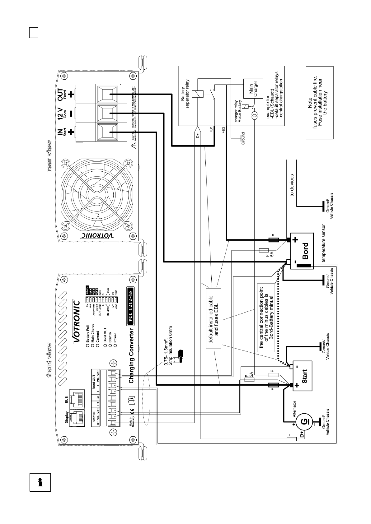
•Integrated On-board Mains Suppression Filter: Unproblematic parallel operation of charging sources (EBL, chargers,
motor-driven and petrol-driven generators, solar systems) on one battery.
•Charging Cable Compensation: Automatic compensation of voltage losses on the charging cables.
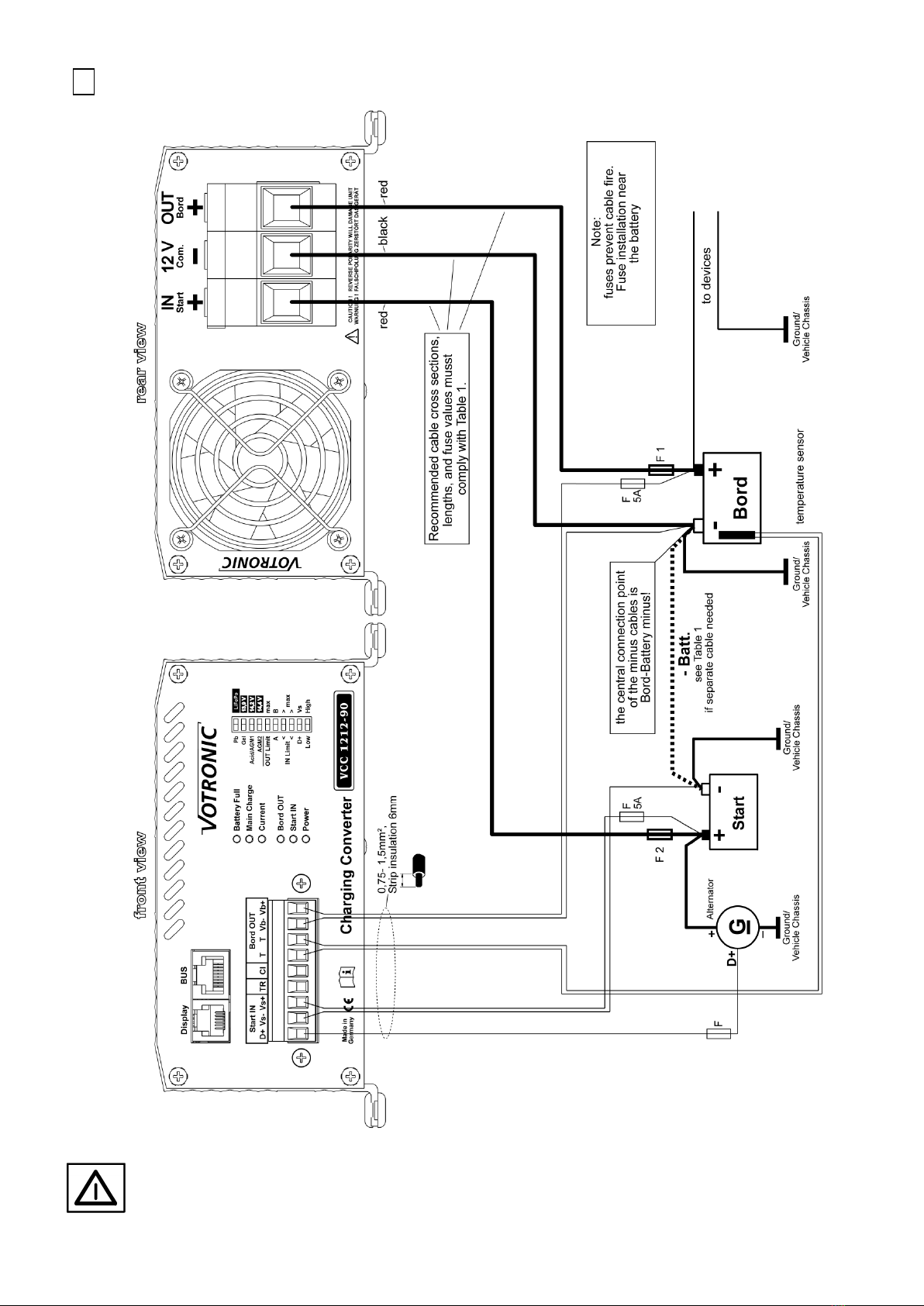
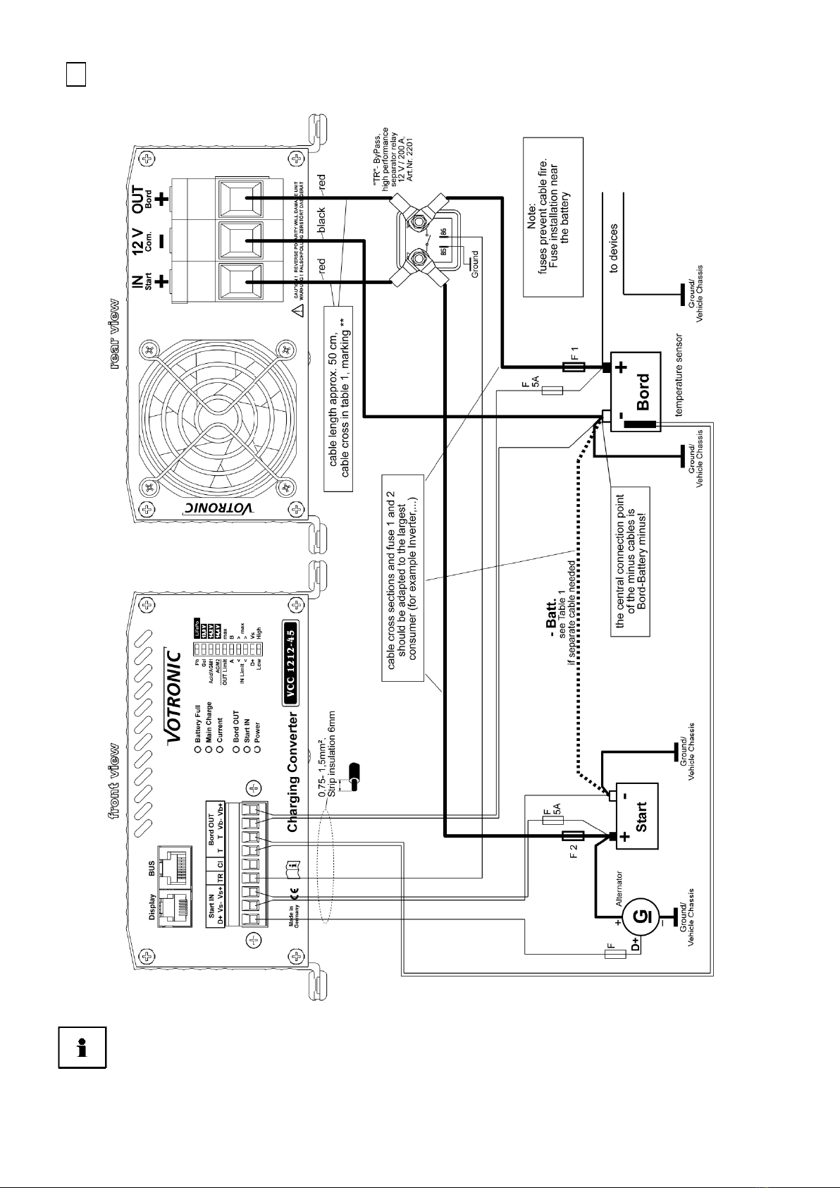
•Connection for Battery Temperature Sensor (included in the standard delivery scope):
Lead batteries (acid, gel, AGM): In case of low outside temperatures, full charging of the weak battery is improved by
automatic adaptation of the charging voltage to the battery temperature, and in case of summery temperatures
unnecessary battery gassing will be avoided.
LiFePO4 Batteries: Battery protection in case of high temperatures and particularly in case of low temperatures < 0° C.
Highly recommended, if the battery temperature might drop below 0 °C during operation.
•Charging Aid for Deeply Discharged Lead Batteries: Gentle preliminary charging of the (lead-acid, gel, AGM) battery
to 8 V, followed by powerful support of the battery, in case of possibly switched-on consumers.

--2--
1
2
3
4
5
Battery Lifetime and Efficiency:
•Keep the batteries cool, LiFePO4 preferably above 0°C. Choose an appropriate location
for installation.
•Store only fully charged batteries and recharge them periodically.
•Open lead-acid batteries and batteries being "maintenance-free according to EN/DIN":
Check the acid level periodically!
•Recharge deeply discharged lead batteries immediately!
•LiFePO4: Only use complete batteries with BMS and safety circuit.
! Deep discharge is to be absolutely avoided!
Installation of the Unit
Install the charger near the board supply battery to be charged (for short charging cables) at a clean, level and hard
mounting surface, which is protected from moisture, humidity and aggressive battery gases. The unit can be installed in any
position.
Despite the charger's high efficiency, heat is produced, which is brought out of the casing by means of the built-in fan. The
vent holes at the unit rear should never be covered (minimum distance 10 cm) to ensure full charging capacity. Ensure
sufficient ventilation in the environment of the unit so that the heat can be dissipated.
Otherwise, in the event of overheating, the charger will reduce its charging capacity.
Unit Connection
a. Choose the appropriate connection plan for the application of the unit:
Standard connection plan, including options,
for all types and power classes, page 3.
Combination with electroblock "EBL", "EVS" with further use of the cabling and fuses of the
customer, which are already existing in the vehicle. Only suitable for VCC 1212-45, page 4.
Combination with electroblock "EBL", "EVS" with the existing cabling of the customer, however with
separate VCC cabling. Suitable for all VCC types with full capacity, page 5.
Special case: In case of a cutoff relay of the customer, which exists in the vehicle and which is in a
very difficult to access location or which is not accessible. Only suitable for VCC 1212-45, page 6.
Special case: In case of temporarily very high consumer current rates, such as with operation of an
air-condition during driving with powerful inverter, page 7.
Option: Usually, the Start IN "Vs- and Vs+" sensor cables are not required when observing the option notes for
tables 1, page 8.
Option: Usually, the Board OUT "Vb- and Vb+" sensor cables are not required when observing the option notes
for tables 1, page 8.
b. Implement 3 power connections observing the tables 1, page 8:
"Recommended Cable Cross-Sections, Cable Lengths and +Fuse Capacities".
Reverse battery (+/-) might result in serious damage of the unit!
c. Produce the control connections. See description from page 9,
"Configuration of the 9-pole Plug-in Terminal Strip (Sensor Inputs and Terminal)"
Unit Settings
d. How to set the charging program "Board" battery (type, design, technology acid, gel, AGM, LiFePO4), from
page 11.
e. Adjustment of the further settings and functions, setting of the six (6) slide switches, from page 14, tables
2, 3, 4.
Start-up and Function Test:
f. Further description, see page 17.

--3--
1
Standard Connection Plan incl. Options, All Types:
Safety Instructions for All Connection Methods:
•Observe the cross-sections and lengths of the cables.
•Never mix up the voltage sensor cables for start (Vs- and Vs+) and board (Vb- and Vb+)!
•Insert fuses near the battery for protection of the cables.
•Reverse battery (+/-mix up) at the large power terminals will result in serious damage of the unit!

--4--
2
In combination with electroblock "EBL", "EVS" with further use of the cabling and fuses, which are
already existing in the vehicle. Disconnect the cable to the starter battery.
Only suitable for VCC 1212-45:
The cabling and the fuses for the electroblock provided by the customer are further used.
VCC 1212-45: The switches "IN Limit", see table 3, page 14, can be used to eventually limit the maximum
current draw from the vehicle's starter circuit to avoid an overload of the default installed fuses
and cabling. Please check!
For this reason, it cannot be used for the more powerful types VCC 1212-60 / 75 / 90 !

--5--
3
In combination with electroblock "EBL", "EVS" with the existing cabling of the customer, however
with separate VCC cabling suitable for all VCC types with full capacity:
The default cabling and the fuses for the electroblock EBL provided are further used.
For this purpose, insert a switching relay 12 V / 60 A, order No. 2202, into the cable EBL start.
Connect the ("NC normally closed contact" 87a).
It prevents bridging of the charging converter by the cutoff relay being installed in the EBL.

--6--
4
Special case: In case of a cutoff relay of the customer, which exists in the vehicle and which is in a
very difficult to access location or which is not accessible, disconnect the cable to the starter
battery. Only suitable for VCC 1212-45:
The cabling with the fuses and the cutoff relay provided by the customer are further used.
VCC 1212-45: The switches "IN Limit", see table 3, page 14, can be used to eventually limit the maximum
current draw from the vehicle's starter circuit to avoid an overload of the default installed fuses
and cabling. Please check!
For this reason, it cannot be used for the more powerful types VCC 1212-60 / 75 / 90 !

--7--
5
"TR" Bypass Relay:Special case: In case of temporarily very high consumer current rates, such as
with operation of a air-condition during driving with powerful inverter:
Instructions for faultless function of this option: Connect the charging converter VCC and the
"TR" bypass relay with 2 x approx. 50 cm connection cables, cross-sections acc. to tables 1 (**).
The further cabling to the batteries, including different cross-sections, is to be done directly at
the relay!
The 12 V current requirement of the inverter might be higher than the output capacity of the charging converter. Then, the
charging converter activates automatically the high-performance relay, and the high consumer current can flow directly to
the board battery, which will, however, not be charged, but must supply current instead. If the large consumer switches off,
the charging converter separates the direct connection automatically and resumes its (full) charging and control functions.

--8--
Tables 1: Recommended Cable Cross-Sections, Cable Lengths and +Fuse Capacities
Configuration of the 3 large capacity terminals "Com. –", "OUT Board +", "IN Start +":
•The central connection point of all minus cables for units and batteries is the – pole of the board battery!
•As indicated, a cable "– Batt." is to be laid separately between the two negative poles of the battery
–START and –Board:
In case of insulated bodies!
If required, for relief of the (lightweight) vehicle chassis for the most powerful unit types.
•If a current measuring shunt in the minus cable (for instance, of the battery computer) is used, the central
point of all minus cables is at the measuring shunt, but not at the board battery!
•Full charging capacity during driving mode is ensured, if the cable cross-sections and cable lengths are
observed according to the below-mentioned tables!
•Option: Usually, the Start IN "Vs-and Vs+" sensor cables are not required, if the below-mentioned values for
"Cable Length + START" are only used to approx. 3/4 during the operating mode 4. acc. to table 4, page 15.
•Option: Usually, the Board OUT "Vb-and Vb+" sensor cables are not required, if the below-mentioned values for
"Cable Length + Board" are only used to approx. 3/4.
VCC 1212 - 45
Cable
Cross-Section
Cable Length
"+ START"
In case of
insulated body:
Cable Length
"– Batt."
"Fuse 2"
Cable
Protection
Cable Length
"– Com."
to
"– Board "
Cable Length
"+ Board"
"Fuse 1"
Cable
Protection
6 mm² - - - 0.5 - 1.5 m 0.5 - 1.5 m 50 A
10 mm² **
up to 5 m
up to 5 m
80 A
1.0 - 2.5 m
1.0 - 2.5 m
50 A
16 mm² up to 8 m up to 8 m 80 A 1.5 - 4.0 m 1.5 - 4.0 m 50 A
25 mm² up to 11 m up to 11 m
80 A 2.5 - 6.0 m 2.5 - 6.0 m 50 A
VCC 1212 - 60
Cable
Cross-Section
Cable Length
"+ START"
In case of
insulated body:
Cable Length
"– Batt."
"Fuse 2"
Cable
Protection
Cable Length
"– Com."
to
"– Board "
Cable Length
"+ Board"
"Fuse 1"
Cable
Protection
10 mm² - - - 0.5 - 2.0 m 0.5 - 2.0 m 70 A
16 mm² **
up to 6 m
up to 6 m
100 A
1.5 - 3.5 m
1.5 - 3.5 m
70 A
25 mm²
up to 9 m
up to 9 m
100 A
2.0 - 5.0 m
2.0 - 5.0 m
70 A
35 mm²
up to 12 m
up to 12 m
100 A
-
-
-
VCC 1212 - 75
Cable
Cross-Section
Cable Length
"+ START"
In case of
insulated body:
Cable Length
"– Batt."
"Fuse 2"
Cable
Protection
Cable Length
"– Com."
to
"– Board "
Cable Length
"+ Board"
"Fuse 1"
Cable
Protection
16 mm² ** - - - 0.5 - 2.0 m 0.5 - 2.0 m 80 A
25 mm²
up to 8 m
up to 8 m
125 A
1.5 - 4.0 m
1.5 - 4.0 m
80 A
35 mm² up to 10 m up to 10 m
125 A 2.0 - 5.5 m 2.0 - 5.5 m 80 A
VCC 1212 - 90
Cable
Cross-Section
Cable Length
"+ START"
In case of
insulated body:
Cable Length
"– Batt."
"Fuse 2"
Cable
Protection
Cable Length
"– Com."
to
"– Board "
Cable Length
"+ Board"
"Fuse 1"
Cable
Protection
16 mm² **
-
-
-
0.5 - 1.5 m
0.5 - 1.5 m
100 A
25 mm²
up to 6 m
up to 6 m
150 A
1.0 - 3.0 m
1.0 - 3.0 m
100 A
35 mm² up to 9 m up to 9 m
150 A 1.5 - 4.0 m 1.5 - 4.0 m 100 A
** For special case: "TR" Bypass Relay in case of very high consumer current rates, two connection cables, 50 cm, page 7.

--9--
Connection of the 9-pole Plug-in Terminal Strip (Sensor Inputs, Terminal):
Plug-in Terminal Strip: In case of limited space, the strip can be removed and reinserted at any time for easy cable
connection.
Cable Cross-Sections: 0,75 mm2or more.
Length to be stripped: approx. 6 mm
Protection: All inputs and outputs of this terminal strip are protected against overvoltage, reverse battery
and overload.
"D+": Control input from the generator for function on/off:
Connect the terminal "D+" directly to the existing signal in the vehicle. The D+ signal is preferably to be used for the "active
alternator".
If the D+ signal does not exist in the vehicle, the signal "Ignition ON" (terminal 15) can be used for unit control. However:
Warning: When the engine is not running, the starter battery might be discharged!
In case of pure voltage control of the unit, table 4, items 1. and 2., the terminal is to be left free.
"Vs -" and "Vs +": IN Input Voltage Sensor/Sense Cables to the STARTER Battery (Option):
Measuring inputs for accurate battery input voltage:
With it, the unit is able to measure the exact voltage of the starter battery, independently of the voltage losses on the
supply cables, and to draw conclusions from it concerning the condition of the starter battery (such as rating).
For this, connect the sense cables "Vs-" and "Vs+" directly to the poles of the starter battery. Never connect them to the
interconnected distributors, ground or the like (voltage falsification)!
The cables are not required, if the values in the tables 1 for "cable length "+ START" are only used to approx. 3/4. Then,
leave the terminals free.
Never mix up the sensor cables Start IN ("Vs-"/"Vs+") and Board OUT ("Vb-"/"Vb+"),
otherwise the voltage control of the unit will be led astray!
"TR": Terminal for external bridging relay, see page 7, Special Case
"TR Bypass Relay in case of temporarily very high consumer current rates". If not used, leave the terminal free.
The rating of the output is max. 1 A, and it is protected with a thermal fuse, which resets itself after removal of the
overload and reactivates the output.
"CI": Connection without function, leave the terminal free.
"T T": Measuring input for the temperature of the board supply battery:
Connect the temperature sensor to the terminals "T - T" (any polarity). Further details concerning the functions of the
sensor can be found under the paragraph "Battery Temperature Sensor" and in the charging characteristic lines.
"Vb -" and "Vb +": OUT Output voltage sensor/sense cables to the board battery (option):
Measuring inputs for exact measurement of the board battery voltage (output voltage):
The unit uses the sense cables for the exact measurement and control of the charging voltage at the board battery to be
charged, independently of the voltage losses on the charging cables. For this, connect the sense cables "Vb-" and "Vb+"
directly to the poles of the board battery. Never connect them to the interconnected distributors or the like (voltage
falsification)!
The cables are not required, if the values in the tables 1 for "cable length + START" are only used to approx. 3/4. Then,
leave the terminals free.
Never mix up the sensor cables Board OUT ("Vb-"/"Vb+") and Start IN ("Vs-"/"Vs+").
Otherwise the voltage control of the unit will be led astray!
If several batteries are connected in parallel as battery system (battery bank), cross connection is required:
•Connect "Vb-" to the negative pole of the 1st battery
•Connect "Vb+" to the positive pole of the 2nd or last battery of the system
The charger will automatically recognize and evaluate the sensor cables.
If the sensor cables are not installed, or in case of a cable break or fuse failures, it will be switched to
normal operation with charging cable compensation, that means, the calculated compensation of the
voltage losses on the charging cables within the values in the tables 1.

--10--
Battery Temperature Sensor:
Connect the temperature sensor (included in the standard delivery scope) to the terminals "T T" (any polarity).
The temperature sensor controls the temperature of the board supply battery.
Ensure that the installation place of the sensor is not influenced by any source of heat (engine heat, exhaust, heater
etc.)!
Lead-Acid, Gel, AGM Batteries:
Installation: The thermal contact of sensor and battery inside temperature should be well. Thus, it should be screwed
down to the negative pole or positive pole of the battery. It is also possible to fasten it at the sidewall centre of the battery
casing.
Function: The temperature-dependent charging voltage of the board battery will be adapted automatically to the battery
temperature (automatic temperature equalization). For this purpose, the temperature sensor measures the battery
temperature. In case of low temperatures (winter operation), the charging voltage will be increased, in order to improve
and accelerate full charging of the weak battery. Sensitive consumers are protected by a voltage limitation in case of very
low outside temperatures.
In case of summery temperatures, the charging voltage is reduced to minimize the load (gassing) of the battery and to
extend the lifetime of gas-tight batteries.
Battery Protection: In case of excessive battery temperatures (from +50 °C), the charging voltage will be reduced strongly
to the safety charging voltage of approx. 12.80 V for battery protection, and the maximum charging current rate will be
halved (safety mode, LED "Board OUT" is flashing). Any charging data being recorded hitherto will be kept in memory.
Battery charging is then interrupted, but the supply of possibly connected consumers will be continued by the unit, and the
battery is allowed to cool down. After that, automatic charging will be resumed. Also refer to:
"Lead batteries, 4 characteristic lines, charging voltage rates and temperature equalization" from page 11.
The unit recognizes automatically a missing sensor, cable break or short circuit of the sensor cables, as well as unreasonable
measuring values. In that case, it will switch automatically to the usual charging voltage rates of 20 °C / 25 °C being
recommended by the battery manufacturers.
LiFePO4 Batteries:
Installation: The thermal contact of sensor and inside temperature of the battery should be well. Thus, it should be
screwed down to the negative pole of the battery, because in most of the cases, this is the cooler side (the positive pole is
often biased by the exhaust heat of internal fuses of the battery, electronic systems for cell equalization, balancers etc.)!
Function: In case of abnormal battery temperatures, such as < -20 °C, > 50 °C, the charging voltage will be reduced strongly
to the safety charging voltage of approx. 12.80 V for battery protection, and the maximum charging current rate will be
halved (safety mode, LED "Board OUT" is flashing). Any charging data being recorded hitherto will be kept in memory.
Battery charging is then interrupted, but the supply of consumers being possibly connected will be continued by the
charger until the battery temperature is again within the acceptable range. After that, automatic charging will be resumed.
In case of temperatures below 0 °C, the charging current will be reduced considerably for battery protection, the LED
"Board OUT" will turn off every 2 seconds, and longer charging times can be expected. Also refer to 4 Characteristic Lines
for "LiFePO4 Batteries, Charging Voltage Rates and Temperature Control", from page 12.
Warning: If the charging characteristic line had been set for a LiFePO4 battery, the temperature sensor
must be connected for reasons of battery safety. Otherwise, the unit will not operate, and the LED "Main
Charge" will be flashing!
Option: Several Batteries at the Charging Port:
Parallel charging of two or several batteries of the same voltage (12 V) is admissible.
According to the battery manufacturers, permanent parallel operation is admissible in case of two or several batteries of
the same type (gel/acid/AGM)/LiFePO4), same capacity, as well as of the same age (history) in cross connection.

--11--
Unit Settings:
Carefully move the 10 micro slide switches behind the front panel of the unit to the
desired position using a small screw-driver. The control levers are shown in white.
1.) How to Set the Battery Type "Board"- (Design, Technology):
Eight (8) charging programs for the different battery types are stored in the unit.
They can be selected by means of the upper 4 slide switches:
If not being specified divergently by the battery manufacturer, the suitable charging program for
the board supply battery can be determined by means of the following description and the
technical data (voltage rates U1 and U2).
The possible parallel/floating operation with consumer loads being connected to the
board battery is also automatically considered by all charging programs.
TS = Temperature Sensor (Effect with/without connection of the temperature sensor)
Charging Programs for Lead Batteries (Acid, Gel, AGM):
4 Characteristic lines, charging voltage rates and temperature equalization for batteries in lead
technology:
1"Lead Acid" Switch
Position
U1=14.40 V U2=13.50 V
2-6 h
Universal charging program for
acid-lead-acid batteries acc. to DIN 57 510/
VDE 0510 for charging and trickle charging of
supply (board) batteries.
Ensures short charging times, high charging factor and
acid mixing for open standard batteries and closed,
SLA, low-maintenance, maintenance-free "non-solid
electrolyte", "lead-acid", drive, lighting, solar and
heavy-duty batteries. Also suitable for recently
developed batteries (low-antimonous, with silver-alloy, calcium or similar) and batteries with low (L) and very low (VL) water
consumption.
2"Gel" Switch Position
U1=14.40 V U2=13.80 V
6-12 h
Adapted to closed, gas-tight
Gel/dryfit batteries VRLA with
determined electrolyte, which are
generally requiring longer dwell times U1 to achieve
particularly high capacity storage and to avoid deep
discharge (becoming deaf) of the battery, such as
EXIDE, Sonnenschein, "dryfit", Varta, Bosch, Banner,
Mobil Technology etc. If not being specified
divergently by the battery manufacturer, also
recommended for batteries in round cell technology,
such as EXIDE MAXXIMA (DC).

--12--
3"AGM 1 14.4 V" Switch Position
U1=14.40 V U2=13.50 V
1.5-5 h
Adapted to closed, gas-tight
AGM (absorbed glass mat)/lead-fleece
batteries VRLA with indicated charging
voltage "14.4 V".
4"AGM 2 14.7 V" Switch Position
U1=14.70 V U2=13.60 V
1.5-5 h
Adapted to closed, gas-tight
AGM (absorbed glass mat)/lead-fleece-
batteries VRLA with indicated
voltage "14.7 V or 14.8 V".
It is highly recommended to check the specification
sheet of the battery concerning the high
charging voltage U1 14.7 V!
Charging Programs for LiFePO4 Batteries:
4 Characteristic lines, charging voltage rates and temperature control adapted to lithium batteries:
•Observe the instructions of the battery manufacturer!
•An operation of the unit at a LiFePO4 battery without BMS Battery Management System
and without equalization charging of the cells (balancing) as well as safety circuit is not
admissible!
•The battery temperature sensor must be installed at the battery (screw to the negative pole)
and must be connected at the unit. It serves as protection for the battery.
No function without temperature sensor, LED "Main Charge" is flashing!
•If possible, the battery temperature should be kept above 0 °C.
5"LiFePO4 13.9 V" Switch Position
U1=13.90 V U2=13.90 V
0.5-1 h
Adapted to
•Dometic "eStore"
of the indicated capacity rates.
Operation of the battery only with own BMS
and prescribed safety circuit!

--13--
•The charging regulations of the battery manufacturer are absolutely to be observed!
•An operation of the unit at a LiFePO4 battery without BMS Battery Management System and
without equalization charging of the cells (balancing) as well as safety circuit is not admissible!
•The battery temperature sensor must be installed at the battery (screw to the negative pole)
and must be connected at the unit. It serves as protection for the battery.
No function without temperature sensor, LED "Main Charge" is flashing!
•If possible, the battery temperature should be kept above 0 °C.
6"LiFePO4 14.2 V" Switch Position
U1=14.20 V U2=13.60 V
0,5 h
Adapted to
•Victron LFP-BMS 12,8
•TransWatt TH 12/xxx
of the indicated capacity rates.
Operation of the battery only with own BMS
and prescribed safety circuit!
7"LiFePO4 14.4 V" Switch Position
U1=14.40 V U2=13.80 V
0.3-1 h
Adapted to
•MT-LiFePO4 professional series
of the indicated capacity rates, types with integrated
safety circuit and integrated BMS.
•Super B SB12VxxE
•GNB/Exide SL12 xxxHC with BMS
of the indicated capacity rates. Operation only with
own BMS and prescribed safety
circuit!
8"LiFePO4 14.6 V" Switch Position
U1=14.60 V U2=13.80 V
0,3 h
Adapted to
•Super B SB12Vxx - M (Epsilon)
•RELION Types "RB"
of the indicated capacity rates, types with integrated
safety circuit and integrated BMS.
Operation of other batteries only with own BMS
and prescribed safety circuit!

--14--
2.) Further Settings and Functions, 6 Slide Switches:
OUT Limit – max (Reduction of the charging current to the board battery):
The switch can be used to limit the maximum charging current, in order to be able to charge also smaller
batteries or to avoid an overload of an existing electroblock EBL of the customer:
Table 2:
Switch Position VCC 1212-45 VCC 1212-60 VCC 1212-75 VCC 1212-90
Right: "max." Charging
Current:
0 A - 45 A 0 A - 60 A 0 A - 75 A 0 A - 90 A
Left: "OUT Limit" Charging
Current:
0 A - 38 A * 0 A - 50 A 0 A - 62 A 0 A - 75 A
A – B: (auxiliary charging only in D+ Mode)
How to activate the integrated auxiliary charging for the STARTER battery:
In case of external charging of the board battery (for instance by means of a mains supply charger), the auxiliary
charging for automatic support charging and trickle charging of the vehicle's (lead) starter battery can be
optionally used for extended standstill periods and current consumption at the starter battery (such as by own
current draw of the vehicle, lighting, audio equipment etc.). For this purpose, a part of the charger current is
diverted to the starter battery. It is controlled and supervised to avoid overload of the starter battery.
If a mains supply charger and / or a solar charging controller or an electroblock EBL with a separate charging port
for the starter battery is existing in the system, the function "auxiliary charging" of the charging converter is not
required and should be switched-off.
Switch position to the left "A": Auxiliary charging is switched-off permanently.
Switch position to the right "B": Auxiliary charging is activated. When the board battery had been charged
sufficiently, the starter battery will be automatically and simultaneously
charged with 0..3 A / 5 A.
IN Limit – max (Limitation of the current draw from the starter battery/
starter circuit):
The 2 switches can be used to limit the maximum current draw of the charging converter from the STARTER
battery, such as for low capacity generators, plug-type connectors or other interlinks in the supply circuit, for
instance removable cutoff relays, fuses, weak cables etc., which are less loadable.
The influence of the switches becomes apparent, if the charging converter must do most of the work due to high
charging current and high charging voltage at the output (i. e. the board battery is already close to being fully
charged) and low voltage at the input in the STARTER circuit at the same time.
Table 3:
Switch Position
Max. Current Draw from the STARTER Circuit (Load)
VCC 1212 - 45 VCC 1212 - 60 VCC 1212 - 75 VCC 1212 - 90
63 A 82 A 103 A 125 A
49 A
EBL Mode *) 67 A 83 A 100 A
42 A
EBL Mode *) 55 A 68 A 82 A
33 A
EBL Mode *) 43 A 54 A 64 A
* Please check, if the existing cables and fuse capacities of the customer are used and depending on the
efficiency of the electroblock EBL.

--15--
How to set the operating mode of the starter battery (IN, input side)
The automatic control (activation) of the charging converter after the engine start can be executed in two different ways:
•In case of special applications, voltage-controlled by the increased voltage of the starter battery with running engine
(not for EURO 6 vehicles!)
•Recommended with vehicle "D+" signal (generator active, recommended) or with ignition on (vehicle terminal 15).
Table 4:
Selector
Switch
IN Input Side of the Charging Converter:
Set the operating range and the behaviour of the charging converter up to the starter
circuit. Also refer to
"Function of the Power Control at Starter Battery and Generator", page 17.
1.
Pure Voltage Control of the Charging Converter. Leave Terminal "D+" free:
Because of the high voltage thresholds, only to be used with "Vs-and Vs+" start sensor cables,
sufficiently dimensioned cable cross-sections and powerful generator.
The starter battery will not be discharged under any circumstances.
Increase of the charging capacity: > 13.50 V
Reduction of the charging capacity: < 13.20 V
Switching off threshold: < 13.00 V 30 sec.
2. Pure Voltage Control of the Charging Converter. Leave terminal "D+" free:
Like 1. However, lower switching thresholds, negligible load of the starter battery.
Increase of the charging capacity: > 13.30 V
Reduction of the charging capacity: < 13.00 V
Switching off threshold: < 12.80 V 30 sec.
3. Activation of the Charging Converter by Control Signal "D+" or ignition "Kl.15".
Because of the average-high voltage thresholds, only to be used with "Vs-and Vs+" starter sensor
cables, sufficiently dimensioned cable cross-sections and powerful generator.
Note: A continuous signal at "D+" without running engine might discharge the starter battery!
Increase of the charging capacity: > 12.50 V
Reduction of the charging capacity: < 12.20 V
Switching off threshold: < 12.00 V 30 sec.
4. Activation of the Charging Converter by Control Signal "D+" or ignition "Kl.15".
This operating mode is particularly provided for EURO standard 6, 6+ vehicles with energy
management, start/stop automatics, strongly varying voltage of generator/starter battery during
energy recovery etc.
Generally recommended for operation with electroblock EBL, EVS.
The start sensor cables "Vs-and Vs+" are not required, if the values in the tables 1 for "Cable
Length "+ START" are only used to approx. 3/4.
If the cables are long (losses), these cables are, however, advantageous for full charging capacity.
Control the control input "D+" either with KL.15 (ignition ON) or more safely connect it to D+ of
the vehicle (generator "active"), since in case of a continuous signal without running engine the
starter battery can be strongly discharged!
Increase of the charging capacity: > 11.70 V
Reduction of the charging capacity: < 11.40 V
Switching off threshold: < 11.20 V 30 sec.
Option: Parallel Connection of Two Charging Converters:
An increase of the charging capacity for large battery systems or high loads (such as operation of an air-conditioning system
with low capacity units) can be realized by parallel connection of two identical units. Couple the connections and set both
units to switch position "4" according to table 4.
The separately laid "Vs-and Vs+" start sensor cables are to be distributed to the inputs of both units, also the
"D+" control signal.
Due to the occurring high current rates, the required cable cross-sections of the power supply connections
must be multiplied by two, or they must be observed (tables 1) absolutely in case of separate laying.

--16--
Pilot Lamps:
"Battery Full" (Board battery fully charged, green):
•If it is on: Battery has been charged to 100 %, trickle charge U2, finished.
•If it is flashing: Main charging process is effected in the charging phase U1, indication of the charging state of
75 % (lead), approx. 90 % (LiFePO4) (short flashing), gradual increase to 100 % (long flashing).
•Off: Main charging process is still being executed in the phase I.
"Main Charge" (Main charging board battery, yellow):
•If it is on: Main charging process is effected in the charging phase I or U1.
•Off: Trickle charge U2.
•If it is flashing: 1. Battery temperature sensor is not connected with charging program LiFePO4!
2. External overvoltage board battery > 15.50 V after 20 seconds,
automatic reset after drop to the normal nominal voltage.
"Current" (Charging Current, red):
•The lighting intensity will be reduced or increased depending on the supplied charging
current.
"Board OUT" (Board battery, yellow):
•If it is on: The board battery will be controlled and charged during operation.
•If it turns off shortly Only LiFePO4:
every 2 s: Battery temperature below 0 °C. The charging current can be reduced for battery protection
for all modes of charging. If the battery is discharged, longer charging times.
•If it is flashing: Battery Protection: Battery overtemperature > 50 °C (depending on type), switchover to low
safety charging voltage and half of the max. charging current. Automatic return, as soon as the
temperature is 2 °C less.
"Start IN" (Starter Battery, yellow):
•If it is on: Pilot lamp for the starter battery during operation.
•If it is flashing: The voltage of the starter battery is too low or too high (only with D+ control).
•Is flashing shortly During idle mode and external charging of the board battery (such as mains supply charger)
every 2 sec.: the auxiliary charging for the starter battery is active to keep its starting capacity (only with
switch position "B").
"Power" (Mains, red):
•If it is on: The charging converter had been activated and is ready for operation.
•If it turns off shortly The power control of the charging converter has reduced the output capacity by more than
every 2 s: 30 % (starter battery discharge protection, starting capacity maintained), since the voltage of
the starter battery dropped below the adjusted value for "reduction of the charging capacity"
(Table 4). The charging capacity will be increased automatically, as soon as the voltage exceeds
the value "increase of the charging capacity".
•If it is flashing: 1. Disconnection by safety timer. Duration of the charging phase I was too long (15 hours)
due to too many consumers or defective battery (short circuit of the cells).
Reset only by removal of the signal at "D+ / Kl.15" (engine, ignition off).
2. Internal unit failure (overheating), automatic reset after cooling down.
•Off: Charging converter in idle mode.
All LEDs "Battery Full", "Main Charge", "Current", "Board OUT", "Start IN" and "Power"
are flashing simultaneously:
The positions of the upper 4 selector switches (charging program acid, gel, AGM, LiFePO4) are incorrect. For
reasons of safety, the unit has switched-off.
Set the desired charging program battery type "Board" (design, technology), from page 11.

--17--
Start-up and Function Test:
After connection and setting of the charging converter the function can be tested:
1. Start the vehicle or switch on ignition (K1.15).
-The charging converter will be activated and starts with 3 % of the maximum charging capacity.
-The LEDs "Power”, "Start IN”, "Board OUT” and "Main Charge" will be lighting, LED "Current” is lighting dimly.
2. Increase the speed of the vehicle to increase the voltage at the starter battery until it exceeds the adjusted value for
the "increase of the charging capacity".
-The charging capacity will be increased and is raised to the maximum value or to the required value of the charging
characteristic line, if the board battery is already full.
-The lighting intensity of the LED "Current" will be reduced or increased depending on the charging current.
Tips:
Unit does not start, the LED "Power" is not lighting:
a. Check the voltage at the activation input terminal "D+", > 8 V.
b. In case of pure voltage control, check the voltage rates directly at the terminals according to table 4.
Full charging current is not reached:
c. Check the adjustment of the slide switches "OUT Limit" according to table 2.
d. Board battery is already charged: Turn on devices with high current draw.
e. If required, deactivate the function "IN Limit" shortly for reasons of testing: Both switches to position "right".
f. Start IN Sensor Cables ("VS-"/"VS+"), if used: Check connection, insulation, polarity.
g. Board OUT Sensor Cables ("VB-"/"VB+"), if used: Check connection, insulation, polarity.
h. Never mix up the sensor cables Start IN ("VS-"/"VS+") and Board OUT ("VB-"/"VB+"),
otherwise the voltage control of the unit will be led astray: check.
Full charging current is not reached, the LED "Start IN" is flashing:
i. Check the voltage at terminal +IN Start: >11.5 V. Increase the engine speed, in order that the charging converter is able
to regulate to a higher voltage.
j. Check cabling –Com, +OUT board and fuse I. Check cross-sections and lengths according to table 1. If used, check
cables Vs- and Vs+, Vb- and Vb+, as well as stripped cable ends. Measure the voltage directly at the terminals/their
screws.
k. Check the cabling +IN Start, fuse 2, cross-sections and lengths (also "minus" connection to chassis, if required, cable
"-Batt." from the starter to the board battery) according to table 1.
l. Concealed battery cutoff relay (such as EBL, EVS) bridges the charging converter: Check connection plan.
Operation with EBL, EVS etc.:
m. The charging converter changes permanently between active and quiescent condition: "D+" must arrive directly from
the vehicle, and not from the EBL.
Function of the Power Control at Starter Battery and Generator:
The charging converter is voltage-controlled or activated via the control input "D+". It will be deactivated automatically if
the engine is switched-off. It starts with 3 % of its achievable charging capacity.
The setting of the two slide switches "D+ / Vs and Low / High" (see tables 4, page 15) now affects the further load of the
starter battery circuit supplying current to the charging converter.
After the engine start, also the starter battery shall be charged immediately and its starting capacity shall be maintained.
Therefore, the charging converter does not start charging the board battery, before the voltage value "increase of the
charging capacity" of the starter battery is reached.
The gradual increase of the charging capacity for the board battery by the charging converter will be effected, if the voltage
value "increase of the charging capacity" of the starter battery is still reached and exceeded.
In case of strong load on the starter circuit due to many large consumers and the starter battery’s voltage drops again
below the value "reduction of the charging capacity", such as during engine idling, there will be a gradual reduction of the
charging capacity for the board battery to relieve the starter circuit. But the minimum charging capacity will always be
approx. 3 % of the achievable charging capacity.
If the voltage drops below the "Switching off threshold" for 30 sec., the charging converter will be switched-off
automatically. As soon as the voltage exceeds the threshold "increase of the charging capacity", the converter will be
switched-on, and the capacity will be increased gradually until the required (maximum) charging capacity is reached.
A reduction of the charging capacity by more than 30 % due to insufficient input voltage of the generator will be indicated
by a flashing LED "Start IN". The LED will turn off, as soon as the input voltage is sufficient or when the power requirement
had dropped anyway due to a charged board battery.
The charging converter simulates a larger consumer load at the generator/starter circuit to ensure an activation also with
Euro 6 vehicles with intelligent generators, if required.

--18--
Chronological Sequence at the Board Battery (OUT):
A new, complete main charging cycle will be executed:
•After a standstill of the generator or removal of the control signal "D+".
•If the voltage of the starter battery has dropped below the adjusted switching off threshold for more than 30 seconds.
•When the board battery is brought below the battery reset voltage for 30 seconds due to high load beyond the
maximum charging current.
1. Activation of switched-off LiFePO4 batteries, charging aid for deeply discharged lead batteries, which will be subject
to gentle preliminary charging to approx. 8 V.
2. Maximum charging current (phase I) in the mean voltage range from 8 V to the beginning of the phase U1 for short
charging times. The LED "Main Charge" is lighting, and approx. 75 % (lead), approx. 90 % (LiFePO4) of the capacity
will be charged. The duration of phase I depends on the battery conditions, the load by the consumers and the
charging state. The charging converter records the charging process. For reasons of safety, the phase I will be
terminated by the safety timer after 15 hours, at the latest (cell defects etc.).
3. In case of high battery voltage rates, the charging current will be slightly reduced for battery protection (orientation
phase). After that, automatic switching to the following phase U1.
4. During the phase U1 (LED "Main Charge" is lighting), the battery voltage will be kept constant on a high level. The
green LED "Battery Full" is flashing, and the additional high battery capacity will be charged. The battery charging
current is decreased slowly while full charging is increasing. The charging converter controls the charging time and
the charging current. From these values and from the course of charging being recorded during the phase I, the
charging converter determines the 100 % full charge point of the battery for automatic switching to U2. In contrast
to conventional voltage transformers or boosters with fixed default values for charging current commutation, an
unnecessary long phase U1 is avoided, which might be caused by consumer loads being possibly also supplied, and
which are falsifying the charging current.
LED "Main Charge" will stop lighting.
5. Phase U2 (LED "Battery Full" is lighting permanently): The charging converter has now switched to the lower
voltage for trickle charge maintaining 100 % charge of the battery. Only the low compensating recharging current is
flowing, which is determined by the battery, and which is required for constant conservation of the full charge.
Note:During the phases U1, U2 (battery full) almost the total charger current is available for additional supply of
consumers without any discharge of the battery.

--19--
Declaration of Conformity:
In accordance with the provisions of Directives 2014/35/EU, 2014/30/EU, 2009/19/EC, this
product complies with the following standards or normative documents:
EN55014-1; EN55022 B; EN61000-6-1; EN61000-4-2; EN61000-4-3; EN61000-4-4;
EN62368-1; EN50498.
The product
must not be
disposed of in
the household
waste.
The product is RoHS compliant.
It complies with the directive
2011/65/EU for Reduction of
Hazardous Substances in electrical
and electronic equipment.
Safety Regulations and Appropriate Application:
The charging converter has been designed according to the valid safety regulations.
Appropriate application is restricted to:
1. Charging of lead-gel, lead-AGM or lead-acid batteries of the indicated nominal voltage.
2. Charging of LiFePO4 complete batteries of the indicated nominal voltage with BMS (Battery Management
System) with cell equalization charging (balancing), safety switching and approval.
3. Simultaneous supply of consumers being connected to these batteries in fixed installed systems.
4. Connection in consideration of the indicated cable cross-sections at the inputs and outputs of the unit.
5. Connection in consideration of the battery capacities at the inputs and outputs of the unit.
6. Fuses of the indicated capacity are to be provided near the battery to protect the cabling of the batteries.
7. Technically faultless condition.
8. Installation in a well-ventilated room, protected from rain, humidity, dust, aggressive battery gases, as well as
in an environment being free from condensation water.
Never use the unit in locations where the risk of gas or dust explosion exists!
•Open-air operation of the unit is not allowed.
•Lay the cables in a way, that damage is avoided and observe to fasten them tightly.
•Never lay 12 V cables and 230 V mains supply cables into the same cable conduit (empty conduit).
•Check live cables or leads periodically for insulation faults, points of break or loosened connections. Occurring
defects must be remedied immediately.
•The unit is to be disconnected from any connection prior to execution of electrically welding or work on the
electric system.
•If the non-commercial end-user is not able to recognize the characteristic values being valid for a unit or the
regulations to be observed, a specialist is always to be consulted.
•The user / buyer is responsible for the observation of construction and safety regulations of any kind.
•The unit does not contain any parts, which can be replaced by the user. Even after having been switched-off,
the unit may be live for an extended period (particularly in case of failure).
•Keep children away from the unit and the batteries.
•Observe the safety regulations of the battery manufacturer; deaerate the battery room.
•Non-observance may result in injury or material damage.
•The warranty period is 36 months from the purchase date (against presentation of the sales slip or invoice).
•The warranty will be void in case of any inappropriate utilisation of the unit, if it is used beyond the technical
specification, in case of improper operation or external intervention. We do not assume any liability for any
damage resulting hereof. The liability exclusion is extended to any service being executed by third, which has not
been ordered by us in writing. Service is to be effected exclusively by VOTRONIC Lauterbach.

--20--
Technical Data: VCC 1212-45 VCC 1212-60 VCC 1212-75 VCC 1212-90
Input from the vehicle starter battery "+ IN Start":
Vehicle Starter Battery Nominal Voltage: 12 V 12 V 12 V 12 V
Min. Battery Capacity (Size), recommended: 60 Ah 60 Ah 80 Ah 100 Ah
Input Voltage Range (EURO 6+), D+, controlled: 10.5 - 16.5 V 10.5 - 16.5 V 10.5 - 16.5 V 10.5 - 16.5 V
Input Overvoltage Disconnection (EURO 6+), max.: 16.5 V 16.5 V 16.5 V 16.5 V
Power Consumption max.: 700 W 905 W 1130 W 1350 W
Current Draw (at lowest input voltage) max.: 0.1 A - 63 A 0.1 A - 82 A 0.1 A - 103 A 0.1 A - 125 A
Current Draw Limited, 3 Switch Positions "IN Limit": 49 A, 42 A, 33 A 67 A, 55 A, 43 A 83 A, 68 A, 54 A 100 A, 82 A, 64 A
Auxiliary Charging, Charge/Trickle Charg. 12 V Starter Battery
for External Mains Charging Mode, Switch Position "B": 0 - 3 A 0 - 3 A 0 - 5 A 0 - 5 A
Activation Control Input "D+", from D+, Terminal 15, Ignition: 8 - 16.5 V 8 - 16.5 V 8 - 16.5 V 8 - 16.5 V
IN "Start" Voltage Sensor Cables "Vs-" and "Vs+": Yes / Yes Yes / Yes Yes / Yes Yes / Yes
Terminal "TR", Signal for Bypass Relay / max.: 12 V/1 A 12 V/1 A 12 V/1 A 12 V/1 A
Charging Port at the Board Supply Battery "+ OUT Board":
Charging/Floating/Load Curr., controlled, IU1oU2, Lead, LiFePO: 0 A - 45 A 0 A - 60 A 0 A - 75 A 0 A - 90 A
Reduction at Switch Position "OUT Limit": 0 A - 38 A 0 A - 50 A 0 A - 62 A 0 A - 75 A
Lead-Acid, Gel, AGM Batteries Nominal Voltage: 12 V 12 V 12 V 12 V
Capacity (Battery Size), recommended/ up to: 75-300/400 Ah 100-400/520 Ah 120-500/660 Ah 150-600/800 Ah
Lead Charging Programs Stored in the Memory: 4 4 4 4
Prelim. Charg. Current (Deeply Discharged Batt. <8 V) max: 22 A 30 A 37 A 45 A
Safety Charging Voltage at Battery Overtemperature: 12.80 V 12.80 V 12.80 V 12.80 V
LiFePO4 Battery Nominal Voltage: 12 V-12.8-13.3 V 12 V-12.8-13.3 V 12 V-12.8-13.3 V 12 V-12.8-13.3 V
Capacity (Battery Size), recommended/up to: 75-300/400 Ah 100-400/520 Ah 120-500/660 Ah 150-600/800 Ah
LiFePO4 Charging Programs Stored in the Memory: 4 4 4 4
Safety Charging Voltage at Battery Overtemperature: 12.80 V 12.80 V 12.80 V 12.80 V
Input "T T" for Battery Temperature Sensor "Board": Yes Yes Yes Yes
OUT "Board" Voltage Sensor Cables "Vb-" and "Vb+": Yes / Yes Yes / Yes Yes / Yes Yes / Yes
Quiescent Current, Standby: 13 mA 13 mA 16 mA 16 mA
Charging Timer: 3-fold 3-fold 3-fold 3-fold
Ripple Factor Voltage: < 30 mV rms < 30 mV rms < 30 mV rms < 30 mV rms
Limit of Charging Voltage "+OUT Board" (Consumer Protection): 15.00 V 15.00 V 15.00 V 15.00 V
External Overvoltage Disconnection "+OUT Board" (20 sec.): 15.50 V 15.50 V 15.50 V 15.50 V
Safety Protection against Short-circuit/Back Discharge: Yes Yes Yes Yes
Fitting Position of Unit: any any any any
Temperature Range: -20/+45 °C -20/+45 °C -20/+45 °C -20/+45 °C
Speed-controlled, Temperature-controlled Fan: Yes Yes Yes Yes
Gradual Reduction of Charging Capacity at Overtemperature: Yes Yes Yes Yes
Safety Disconnection in Case of Overheating: Yes Yes Yes Yes
Connection "Display": Yes Yes Yes Yes
Connection "BUS" for VBS Bus: Yes Yes Yes Yes
Dimensions, incl. Fastening Flanges and Terminals (LxWxH): 235x160x71 mm 235x160x71 mm 235x160x71 mm 235x160x71 mm
Weight: 1230 g 1300 g 1400 g 1480 g
Ambient Conditions, Humidity of Air: max. 95 % RH, no condensation
Subject to misprints, errors and technical modification without notice.
All rights reserved, particularly the right of reproduction. Copyright VOTRONIC 07/18.
Made in Germany by VOTRONIC Electronic-Systeme GmbH & Co. KG, Johann-Friedrich-Diehm-Str. 10, 36341 Lauterbach/GERMANY
Phone: +49 (0)6641/91173-0 Fax: +49 (0)6641/91173-20 E-mail: info@votronic.de Internet: www.votronic.de
Delivery Scope:
•Charging Converter Temperature Sensor 825
•Operating Manual
•Temperature Sensor 825
Available Accessories:
•High-capacity Cutoff Relay 12 V / 200 A Order No. 2201
•Switching Relay 12 V / 60 A Order No. 2202
•LED Remote Control S Order No. 2076
•LCD-Charge Control S-VCC Order No. 1248
This manual suits for next models
7
Table of contents
Other Votronic Batteries Charger manuals

Votronic
Votronic Pb 1280 SMT 2B User manual

Votronic
Votronic VAC 1215/15 DUO User manual

Votronic
Votronic Pb 1240 User manual

Votronic
Votronic Pb 1215 SMT 2B User manual

Votronic
Votronic Pb 1210 SMT 2B User manual

Votronic
Votronic VAC 1215 M 3A User manual

Votronic
Votronic PFPN 1204 User manual

Votronic
Votronic Pb 1240 SMT 3B Technical document
Popular Batteries Charger manuals by other brands

Spectrum
Spectrum InTouch 20 Cart with Sync Charge owner's manual

Villager
Villager VCBM 4.0 Original instruction manual

HIKOKI
HIKOKI UC 36YSL Handling instructions

Schumacher
Schumacher SE-1-12S owner's manual

iLive
iLive IPC5205G user guide

Associated Equipment
Associated Equipment IBC6008 Operator's manual