VS Serie 1000 User manual

VS Vereinigte Spezialmöbelfabriken GmbH & Co. KG
http://links.vs-service.com/downloads/70-173_V03_DEEN_Serie-1000-Verkabelung-165938.pdf
Allgemeiner Hinweis zum Lesen und
Aufbewahren der Anleitung:
Lesen Sie diese Anleitung und vor allem die Sicherheits-
hinweise vor Benutzung der Produkte genau durch und
beachten Sie diese. Bewahren Sie die Anleitung zum späteren
Nachlesen sorgfältig auf und geben Sie diese an andere
Benutzer weiter.
Allgemeiner Sicherheitshinweis:
In unseren Bedienanleitungen verwenden wir folgende
Symbole und Hinweise:
Achtung! Bei diesem Symbol handelt es sich um einen
sehr wichtigen Hinweis.
VERKABELUNGSANLEITUNG 70-173 V03 000918
Serie 1000.
Verkabelung für Servicefachkräfte.
Im Internet:
Sie finden diese Anleitung im Internet (siehe Kopfleiste).
Betrieb:
Beachten Sie die Hinweise auf den folgenden Seiten.
Fehlersuche und Service:
Bei eventuell auftretenden Fehlern, wenden Sie sich bitte an
Wartung und Reinigung:
Im Internet: vs.de/kataloge/reinigung/
Weitergabe und Entsorgung:
Bei Weitergabe des Produkts ist auch diese Montageanleitung
zu übergeben. Die gekennzeichneten E-Komponenten dürfen
nicht über den Hausmüll entsorgt werden.
Sie müssen von dem Möbel getrennt werden, bevor
das Möbel der Entsorgung zugeführt wird.
Die Entsorgung erfolgt an zugelassenen Sammel-
und Rücknahmestellen..

2
1
(7)
(6)
(1)
(2)
(3)
(5)
(8)
Achtung! Änderungen im Kabelmanagement sind nur
von geschulten Fachleuten durchzuführen.
Die elektrische Ausrüstung des Tisches ist regelmäßig
zu überprüfen. Fehlerhafte Kabel sind sofort auszutau-
schen. In der Energieführungskette (Igus Z08.30.038
oder gleichwertig) dürfen nur hierfür geeignete Kabel
eingelegt werden.
Vorbereiten.
[Bild 1] Tisch hochfahren und stromlos setzen. Verriegelung
(1) der Tischplatte kurz nach links ziehen und gleichzeitig
Tischplatte bis zum Anschlag nach vorne ziehen. Stecker von
Steckdosenleisten (Bestückung ist auftragsabhängig) (2)
und (3) ziehen. Kabel freilegen.
Achtung! In vorgeschobener Position darf die Tischplatte
nicht belastet werden!

3
2 3
5
4
(5)
(5)
(22)
(26)
(21) (21)
(13)
(7)
(5)
(8)
(12)
(13)
(13) (20)
(11)
(7)
(6)
(4)
(5)
(8)
(9)
(10)
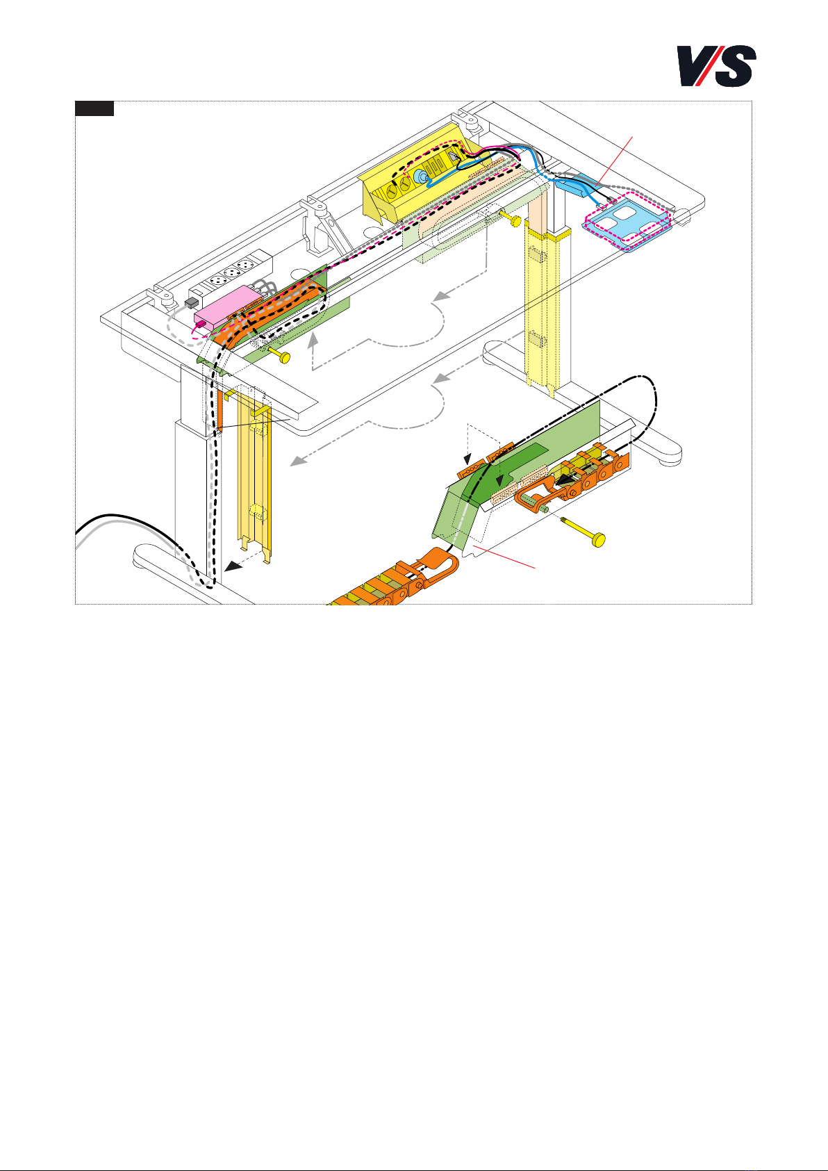
Schlaufe führen. Haken am Rundrohr (20) einclipsen und
Kabel mit der Zugentlastung (8) fixieren. Der Freilauf der
Kabelkette ist sicherzustellen!
Kabelführungsschlitten und Steigkanal
einbauen.
[Position des Steigkanals rechts - Bild 5 + Bild 2] Über-
längen der Kabel von unten in Kabelwanne ablegen. Schlitten
von unten zwischen Kabelwanne und Zarge nach oben führen
und über die Kabelwanne einhängen. Den Schlitten nach
rechts bis zum seitlichen Anschlag am Tischbein schieben.
Mit Rändelschraube (6) Schlitten am Kabelkanal verschrau-
ben. Kabel in die zwei Kabelclipse (26) am Steigkanal einfä-
deln. Steigkanal mit Haken (21) unten in Kufe einhaken und
oben mit der Kunststoffklammer (22) an die Säule clipsen.
Ende der Kabelkette in Steigkanal (11) einclipsen.
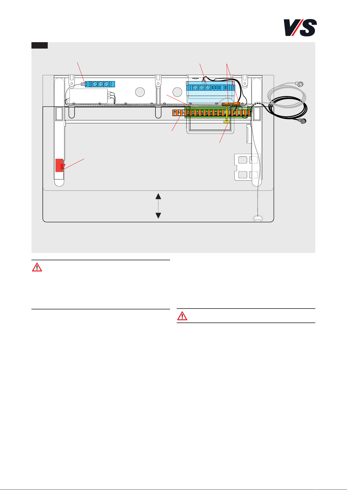
Abschließende Arbeiten.
Stromkabel an Steckdosenleisten anschließen. Hierzu ggf. die
Steckdosenverkleidung mittels den zwei Rändelschrauben
lösen. Für den Austausch der Steckdosenleiste die 4 äußeren
Knöpfe (10) an der festen Steckdosenleiste zum Lösen drücken,
anschließend wieder einrasten. Alle Kabel unter die Abdeckung
(9) führen. Tischplatte bis zum Einrasten in Ausgangsposition
zurückschieben.
Achtung!
Um Quetschungen zu vermeiden, ist ca. 13 cm
vor der Endstellung ein Sicherheitsstop eingerichtet.
Die Tischplatte kann erst nach erneutem Betätigen der
Verriegelung in die Endstellung geschoben werden!
Kabelführungsschlitten ausbauen.
[Bild 2] Steigkanal
(4)
am Tischbein abziehen und Kabelkette
(5)
ausclipsen. Rändelschraube
(6)
unter dem Tisch lösen
und ganz herausziehen. Schlitten
(7)
der Kabelkette leicht
anheben, nach vorne kippen und nach unten herausnehmen.
Zusätzliche Kabel einlegen.
Schlitten mit Kabelkette auf dem Boden ablegen. Zugent-
lastungen (8) der Kabelführung öffnen.
Kabelkette mit Kabel aus dem Schlitten ziehen und mit
Öffnung nach oben auf dem Boden ablegen.
Ein zusätzliches Kabel einlegen.
[Bild 3] Das zusätzliche Kabel in Kabelkette eindrücken.
Beachten Sie, dass der Steckertyp auf der richtigen Seite ist!
Mehrere zusätzliche Kabel einlegen.
[Bild 3 + Bild 4] Alle Kabel aus Kabelkette nehmen. Neue
und alte Kabel zusammen in Einfädelhilfe (12) einlegen und
durch Kabelkette ziehen. Dabei immer an der Seite mit dem
Haken (13) beginnen. Beachten Sie, dass die Steckertypen auf
der richtigen Seite sind [Bild 4] und planen Sie ausreichende
Kabelüberlängen ein.
Achtung! Die Überlängen können nur bei waagrecht
liegender Kabelkette korrigiert werden!
Überknickte Glieder der Kabelkette wieder begradigen und
Kabelkette in Schlitten einführen [Bild 5]. Dabei muss die
Öffnung der Kabelkette nach unten zeigen und die Seite mit
dem Haken (13) vorne sein! Kabelkette im Schlitten in

4
6
(16)
(17)
(18)
(14)
(15)
Installation des Rechners, Rechner und
Steigkanal sind auf der gleichen Seite:
Rändelschraube lösen und Kabelführungs-Schlitten verfahren,
so dass ein Freiraum für die Kabelinstallation (18) unter
dem Tisch zugänglich ist. Kabel für den Rechner von der
Kabelwanne aus über die Kabelpritsche (18) zum Rechner
führen und anschließen.
Schlitten wieder bis zum seitlichen Anschlag am Tischbein
positionieren. Mit Rändelschraube Schlitten am Kabelkanal
verschrauben.
Installation des Rechners, Rechner und
Steigkanal sind auf verschiedenen Sei-
ten:
Kabel für den Rechner von der Kabelwanne aus über die
Kabelpritsche (18) zum Rechner führen und anschließen.
Ummontieren von Kabelschlitten und
Steigkanal.
[Bild 6] Sollen die Kabelzuführungen und der Steigkanal am
Tisch von der rechten
(14)
auf die linke Seite
(15)
(oder um-
gekehrt) ummontiert werden, so muss der Schlitten gedreht
und am Schlitten die Position
(16)
der Zugentlastung um-
montiert werden!
Die abgeschrägte Seite
(17)
des Schlittens zeigt immer zum
Tischbein mit dem Steigkanal.
Abfolge der einzelnen Montageschritte siehe Seite 2 und 3.
Es ändern sich jedoch die notwendigen Überlängen.

5
VS Vereinigte Spezialmöbelfabriken GmbH & Co. KG
http://links.vs-service.com/downloads/70-173_V03_DEEN_Serie-1000-Verkabelung-165938.pdf
General note on reading and storing the
instructions:
Please read these instructions and in particular the notes on
safety carefully and in full before using the products. Keep
the instructions in a safe place for subsequent reference and
pass them on to other users.
General note on safety:
We use the following symbols and notes in our assembly
instructions:
Caution! This symbol refers to
an important note on assembly.
CABLING INSTRUCTION 70-173 V03 000918
Serie 1000.
Cabling instructions for service personnel.
On the internet:
Alternatively, they can be downloaded: (see header title).
Operation:
Follow the instructions on the following page.
Troubleshooting and service:
If faults occur, please contact our
Maintenance and Cleaning
On the internet: vs.de/kataloge/reinigung/en
Transfer and Disposal:
If the product is transferred to another party then it must be
accompanied by these Instructions.
The indicated electric and electronic components must not
be disposed of with the ordinary waste.
They must be removed from the furniture unit
before the unit is sent for disposal.
They are to be disposed of at authorized collection
and return points.

6
1
(7)
(6)
(1)
(2)
(3)
(5)
(8)
Important! Changes to the cable management may
only be carried out by experts. The table’s electrical
equipment must be checked on a regular basis. Faulty
cables must be replaced immediately. Only suitable
cables may be inserted in the cable drag chain
(Igus Z08.30.038 or similar).
Preparation.
[Fig. 1] Move the table upwards and isolate from the power
supply. Pull lock (1) of the table top a little to the left and at
the same time pull the table top forwards up to the stop. Pull
the plugs from socket strips (installed equipment is order-
dependent) (2) and (3). Expose the cables.
Important! Do not subject the table top to load when
in the pushed-forward position!

7
2 3
5
4
(5)
(5)
(22)
(26)
(21) (21)
(13)
(7)
(5)
(8)
(12)
(13)
(13) (20)
(11)
(7)
(6)
(4)
(5)
(8)
(9)
(10)
carriage in the loop. Clip in the hook on round tube (20) and
secure the cable with strain-relief device (8). Make sure the
cable chain can run freely.
Installing cable guide carriage and
rising channel.
[Position of rising channel on right -
Fig.
5 +
Fig.
2] Lay
excess cable lengths from below in the cable tray. Guide the
carriage from below between the cable tray and frame in an
upward direction and suspend over the cable tray. Slide the
carriage to the right up to the side stop on the table leg.
Screw the carriage to the cable channel with knurled screw
(6). Feed the cable into the two cable clips (26) on the rising
channel (11). Hook the rising channel with hooks (21) at the
bottom into the skid and clip at the top with plastic retainer
(22) to the leg/post. Clip the end of the cable chain into rising
channel (11).
Concluding tasks.
Connect the power cables to the socket strips. To do so, if
necessary release the socket panel by means of the two
knurled screws. To exchange the socket strip, press the 4 ou-
ter knobs (10) on the fixed socket strip to release, then snap
into place again. Guide all cables under cover (9). Slide the
table top back until it engages in its initial position.
Important! A safety stop is set up approx. 13 cm before
the end position to avoid crushing. The table top can
only be slid into the end position after the lock has
been actuated again.
Removing the cable guide carriage.
[Fig. 2] Detach rising channel
(4)
on the table leg and unclip
cable chain
(5)
. Release knurled screw
(6)
under the table and
pull out fully. Raise carriage
(7)
of the cable chain slightly,
tilt forwards and remove in downward direction.
Inserting additional cables.
Lay the carriage with cable chain on the floor. Open strain-
relief devices
(8)
of the cable guide.
Pull the cable chain with cable out of the carriage and lay
with the opening facing upwards on the floor.
Inserting an additional cable.
[
Fig.
3]
Press the additional cable into the cable chain. Make
sure that the plug type is on the correct side!
Inserting several additional cables.
[
Fig.
3 +
Fig.
4] Remove all cables from the cable chain. In-
sert new and old cables together in threading aid (12) and
pull through the cable chain. Always start on the side with
hook (13). Make sure that the plug types are on the correct
side [
Fig.
4] and allow for excess cable lengths.
Important! The excess lengths can only be corrected
when the cable chain is lying horizontal!
Re-straighten overkinked links in the cable chain and insert
the cable chain into the carriage [Fig. 5]. Here the opening
of the cable chain must point downwards and the side with
hook (13) must be at the front! Guide the cable chain in the

8
6
(16)
(17)
(18)
(14)
(15)
Installing the computer, computer and
rising channel on the same side:
Release the knurled screw and move the cable guide carriage
so that clearance for cable installation (18) under the table
is accessible. Feed the cable for the computer from the cable
tray over cable rack (18) to the computer and connect.
Position the carriage again up to the side stop on the table
leg. Screw the carriage to the cable channel with the knur-
led screw.
Installing the computer, computer and
rising channel on different sides:
Feed the cable for the computer from the cable tray over cable
rack (18) to the computer and connect.
Repositioning cable carriage and rising
channel.
[Fig. 6] If the cable feeds and the rising channel on the table
are to be repositioned from the right side
(14)
to the left side
(15)
(or vice versa), the carriage must be turned and on the
carriage position
(16)
of the strain-relief device relocated.
The sloping side
(17)
of the carriage always points to the table
leg with the rising channel.
For the order of the individual assembly steps, see Pages 2
and 3. However, the necessary excess lengths are different.
Table of contents
Languages:
Other VS Tools Storage manuals