WABCO IVTM Guide

Integrated Vehicle Tire
Pressure Monitoring
Vehicle tire pressure
monitoring system
System functions
System configuration
Instructions for installation
and diagnostics
1st. edition
815 000 452 3
8150004523
Revisions of this document are not set up.
New versions could be found in INFORM website
www.wabco-auto.com
ÓCopyright WABCO 2004
Vehicle Control Systems
An American Standard Company
8150003993
Changes are reserved
Version 001/04.03(en)
Wabcodruck 815 000 452 3

FCC Notice
This device consists of Wheelmodul 960 730 XXX X (SA4-WM730)
and Electronic Control Unit 446 220 XXX X (SA4-ECU220)
This device complies with Part 15 of the FCC Rules. Operation is
subject to the following two conditions:
(1) this device may not cause harmful interference, and
(2) this device must accept any interference received, including
interference that may cause undesired operation.
Changes or modifications not expressly approved by the party
responsible for the compliance could void the user's authority to
operate the equipment.

3
1
Contents
1. System functions 5
1.1 System structure 7
1.1.1 Example of installation in the bus 8
1.1.2 Example of installation in the trailer 8
2. Configuration 9
2.1 Components 10
2.1.1 Wheel module 10
2.1.2 Electronic control unit (ECU) 12
2.1.3 Display 13
2.2 Wiring 14
3. Installation instructions 17
3.1 General instructions 17
3.2 Overview 17
3.3 Additional mounting into vehicle/bus 18
3.3.1 Additional mounting into trailer 19
3.4 Inflation pressure 19
3.5 Installation of the control unit in vehicle 20
3.5.1 Installation of the wiring harness in vehicle 20
3.5.2 Installation of the wiring harness in trailer 22
4. Diagnostics 26
4.1 System configuration 26
4.2 Diagnostics structure 26
4.3 Instructions for use 27
4.3.1 Display instructions 27
4.4 Various information on display 27
4.4.1 Normal data 27
4.4.2 Pressure data 28
4.4.3 Error messages 29
4.4.4 Display reset 30
4.5 System error signalization 31
4.5.1 Interrupted connection to the wheel module 31
4.5.2 System failure 31
4.5.3 Interrupted connection between control unit and display 31

5
1. System functions
IVTMstands for Integrated Vehicle Tire Pressure
Monitoring. It is the tire pressure monitoring system,
which is installed in the vehicle. IVTM continuously
monitors the pressure in all tires. This monitoring is
performed by the pressure sensors in all tires, which
relays information to the display in the cabin and warns
driver about critical pressure drop. IVTM makestransport
safer and more efficient, because more than 80 % of tire
damage could be recognized before serious damage
occurs, which requires repair. IVTM thus cuts down
operational costs, as continually maintained optimized
pressure in all tires results in minimal fuel consumption
and extension of service life of tires.
Let us present some information:
Tire manufacturers estimate that total losses caused by
improper maintenance of tires of commercial vehicles are
more than 10 millions of Euro in Germany. Lot of vehicle
users unfortunately tend to overlook this important factor
of operational costs. By selecting correct tires and proper
maintenance it is possible to save up to 2500.- €per
vehicle for one year. The unnecessary expanses are
further increased by widely spread carelessness of
driving with under-inflated tires. Tires with 20 % lower
pressure are no exception in everyday life. This under-
inflation reduces service life of tires by 20 % and
unnecessarily increases fuel consumption.
In order to minimize these costs WABCO company
designed new system IVTM, which also increases traffic
safety.
System functions 1.
IVTM
Main reasons for brakedowns at commercial vehicles are:
Brakes 4%
Electric 17%
Tyres 26%
Engine 36%
Operating
supplies 1%
Chassis 2%
Service / information 3%
Structure 3%
Salvage operation 4%
Drive line 4%
Source: Service 24 GmbH & Co. KG
66000 brakedown missions
for trucks and busses in 1999
Fuel consumption
Tire pressure
Service life reduction
The mileage of tyres significantly depends
on the tyre pressure... and fuel consumption also depends on the
tyre pressure.
tyre pressure
too low
tyre pressure
too low
tyre pressure
too high
tyre pressure
too high

6
System functions
IVTM
1.
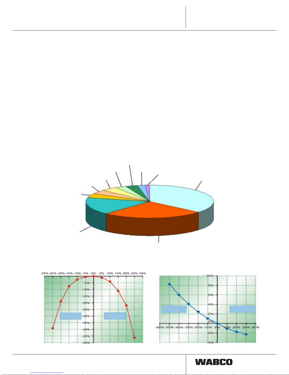
Checks of the car fleets show:
Every second tire is under-inflated by more than
10 %.
Using of new IVTM system increases profitability :
• reduced fuel consumption due to lower rolling
resistance
• smaller tire wear owing to lower deformation
losses => longer tire life cycle
• Saving costs of manual tire pressure check
(up to 30 minutes for one vehicle)
• spare tire is not needed due to low probability of
rupture
=> higher vehicle load.
tyre pressure too low
IVTM warns driver about sneak pressure drop
early, i.e. before the tire could burst.
IVTM enhances safety of passengers, driver, vehicle and
traffic :
• The driver may react to sneak pressure drop
early and prevent up to 85 % of tire bursts.
• Additionally, properly maintained pressure in
tires ensures safe driving properties of vehicle
and short braking distance.
IVTM ensures travel efficiency:
• Prevents unnecessary delays and idle time.
• No backup vehicles/emergency actions needed
• Prevents loss of confidence from unsatisfied
customers and resulting drop of turnover.
Which types of pressure monitoring are
available?
Permanent tire pressure monitoring during driving could
be performed in several ways:
– direct tire pressure measurement
permanent on-line pressure monitoring is possible.
Extremely precise and effective, very expensive.
– direct tire pressure measurement with limit value
monitoring
not so precise.
– indirect tire pressure measurement
moderately expansive, not nearly as precise and
reliable. The pressure is calculated from drive slip,
measured by ABS turning sensors.
WABCO IVTM uses direct pressure
measurement and in comparison with systems
using ABS presents these advantages:
1. pressure monitoring during parking or before driving
start; diagnostics memory
2. able to distinguish uniform diffusion losses
3. fast detection of pressure drop, reaction time in order
of several seconds.
4. display of current tire pressure
5. higher precision
6. identification of leaking tire
7. measurement is not affected by driving on low quality
road
8. measurement is not affected by uneven vehicle
loading
Air pressure
in bar
records about tire pressure (rise)
VEHICLE
rear axle inside
TRAILER
3 axles
VEHICLE
front axle
The range of tire pressure oscillation for utility vehicles is far higher then for passenger car.

7
This requires using sophisticated evaluation algorithm,
instead of using simple identification of limit value.
Other requirements for tire pressure monitoring
systems of utility vehicles:
• exact wheel identification for vehicles with more
than 10 wheels or with double wheels
• high efficiency of wireless data transport
• pressure range 2 - 14 bars
• Identification of tire pressure fluctuation based
on load and tire wear.
This function requires complicated "evaluative
algorithm".
• Wheel modules must be mounted flexible with
respect to different types and locations of tire
valves on rims, different rim designs and
frequent wheel changes and must allow easy
exchange.
1.1 System architecture
WABCO system is based on one electronic circuit 446
220 00x 0, so called control unit, which receives wireless
data transmitted by wheel modules. Wheel modules 960
730 00x 0 are connected to the wheel valves by hoses.
Pressure information is processed by algorithms stored
in control unit.
The information is sent through CAN bus to display unit
446 221 000 0. Display unit consists of one display, two
indicators, one buzzer and two buttons.
Warning massages of different levels are displayed;
indicator colour and type of audio signal shows
seriousness of the problem:
• Red light and 1 minute long audio signal
indicates serious defect; the vehicle must be
stopped immediately (possible threat to lives
and vehicle).
• Yellow light and 10 minutes long audio signal
indicates smaller defect; the vehicle should be
slowed down and lower pressure adjusted.
Defects found by IVTM system are stored in electronic
memory (EEPROM) for diagnostic purposes.
System functions IVTM 1.
Wheel module
fro wheel
Control unit
Trailer
Vehicle
Control unit
Display:
« Standalone » or integrated
IVTM system
Vehicle
CAN bus
IVTM system
Trailer
CAN bus or
HF wireless data transfer
from trailer control unit
to vehicle control unit

8
System functions
IVTM
1.
1.1.1 Example of installation in the bus:
1.1.2 Example of installation in the trailer:
Driver display
wheel module
electronic control unit (ECU)
Display Control unit
Vehicle Control unit
Trailer wheel module
(one module per one tire)

9
Configuration IVTM 2.
2. Configuration
In order to display tire pressure and trailer warnings to
driver during driving it is in general case necessary to
install IVTM to both parts of vehicle, i.e. one control unit
to trailer and one unit to motor vehicle. Any vehicle
equipped with IVTM could be connected to any trailer
equipped with IVTM. Control unit of vehicle identifies
control unit of trailer automatically: Synchronization is
ensured through the break lights wiring, data are
transported wirelessly.
As trailers are usually not permanently powered, it is
possible that due to the frequency of wheel modules
transmission the tire pressure data for all the wheels
could be available after up to 15 minutes after the drive
start.
In combination with WABCO-TCE (Trailer Central
Electronics) or EBS systems the information about the
pressure could be transmitted into control unit through
standardized bus connection CAN according to 11992.
Future vehicles will be able to display the data from CAN
bus on multifunction display on the dashboard. If such
vehicles will not be available, data will be transferred to
the vehicle control IVTM unit wirelessly.
Certificates
Certificates for mounting and additional mounting of
IVTM are available, which significantly facilitate approval
of vehicle registration papers. Certificates are not part of
this booklet, however in case of need they could be or-
dered in WABCO or by Internet at www.wabco-auto.com
:
Ordering number 815 000 414 3 (D) / 815 000 415 3 (GB)
Contents: Expertise
TÜH ATC - TB 2002-108.00 and
Certificate part of TÜH ATC - TB 2003-023.00
Ordering number 815 000 441 3 (D)
Contents: Model verification 94/9/EG
CE 0032, TÜV03 ATEXxxxx
Aplication range ex II 2G EEx ib IIC T4
CAN bus
CAN bus
Wheel
modules
Wireless connection
Wireless connection
TCE/
EBS
IVTM ECU
Trailer
vehicle
IVTM ECU
Vehicle
IVTM display
IVTM ECU
Vehicle
IVTM display
IVTM ECU
Trailer
vehicle
data transfer
wireless connection to TCE or EBS,
wireless data transfer
Integrated display Integrated display
IVTM ECU
Vehicle IVTM ECU
Vehicle
CAN
J1939
CAN
J1939
Central
computer Central
compute
r
Wheel
modules
ISO 11992
EBS
ISO 11992
EBS
connection to TCE,
data transfer by CAN bus
TCE
Trailer
Central
Electronics
IVTM ECU
Trailer
vehicle
IVTM ECU
Trailer
vehicle
connection to EBS,
data transfer by CAN bus
System structure

10
Configuration
IVTM
2.
Possible vehicle configuration:
Motor vehicle
4 x 2 4 x 2 6 x 2 6 x 2 6 x 2 / 6 x 4 6 x 2 / 6 x 4 8 x 4
Super-Single with with Super-Single
Steering-/ Steering-/lifting axle
Loading axle Super-Single
Trailer vehicles
1-axle 2-axles 3-axles 1-axle 2-axles 3-axles
trailer vehicle trailer vehicle trailer vehicle trailer vehicle trailer vehicle trailer vehicle
with double with double with double
tires tires tires
2.1 Parts
2.1.1 Wheel module
Wheel module is cast in plastic enclosure and is
composed of:
• pressure sensor 2-14 bars
• electronic circuits for data procession
• electronic circuits for data transmission
• lithium-battery
• 24 bit identification code
Life cycle of the battery > is five years under normal
operating conditions.
Wheel module is mounted by the standard nuts from
outside to the shank to rim and is connected to valve.
Result is:
+easy installation, tire dismounting is not necessary
+high quality of wireless data transfer
+Modules remain in their place even during tire
change, i.e. the system does not have to be newly
setup.
The wheel module must not disrupt wheel balance;
therefore the counter weight is mounted on the opposite
side.
Evaluation and data transfer is provided by 433 MHz
signal. If the pressure is constant, measured values are
transmitted every 15 minutes, if the pressure is changing,
frequency of data transfers is faster.

11
Special identification code of each wheel allows unique
assignment of modules to particular wheels. Possibility of
receptions of signals from another vehicle is excluded.
Installation instructions:
–Single tires (front axle, lifting axle,
trailer axle, Super-Single):
1 wheel module + 1 weight
–Double tires (rear axle):
2 standard wheel modules for outer wheel.
Please do not use plastic valve extensions, as these
parts are not designed for permanent pressure load. Use
instead brass extensions (i.e. Alligator V 153-MS-R,
length 177 mm, type 332 903) or flexible valve extensions
with clamps.
Remark:
During hose installation ensure that wheel module
connection is not exposed to excessive mechanical load
or excessive pressure.
Do not use excessive force when tightening cup nut of tire
inflation valve. Check connection seal with test spray.
Replace damaged O rings of wheel module connection:
4.47 x 1.78 EPDM 70
Wheel module mounting on front and lifting
axle
For wheels 22.5 x 7.5, 22.5 x 8.25, 22.5 x 9 10 holes,
pitch circle diameter 335 mm, ET 160
Wheel with protective nut circle:
L-Shape wheel module 960 730 001 0 with hose 960 730
056 4. Install counter weight on opposite side.
Wheel with axle cap:
Wheel module 960 730 001 0 with module 960 730 057
4. Counter weight 960 730 820 4 on opposite side.
Wheel module installation on rear axle with
double tires
For wheels 22.5 x 7.5, 22.5 x 8.25, 22.5 x 9 10 holes,
pitch circle diameter 335 mm, ET 160
2 wheel modules 960 730 001 0
Hose for outer wheel: 960 730 054 4 (22.5 x 7.5,
22.5 x 8.25 und 22.5 x 9)
Hose for inner wheel: 960 730 055 4 (22.5 x 7.5)
respectively 960 730 058 4 (22.5 x 8.25 and 22.5 x 9)
Counter weight is not needed.
Configuration IVTM 2.

12
Configuration
IVTM
2.
Wheel module installation on axle
of trailer with single tires and Super-Single
For trailer wheels 22.5 x 11.75 ET 0 and 120; Super-
Single wheels 22.5 x 11.75, 22.5 x 15, 22.5 x 17, 10 holes
pitch circle diameter 335 mm
ET 0
ET 120
Wheel module 960 730 001 0
Hose for trailer wheel 22.5 x 11.75 ET 0:
960 730 055 4
Hose for trailer wheel 22.5 x 11.75 ET 120:
960 730 053 4
Hose for Super-Single wheel 22.5 x 11.75 and
22.5 x 15: 960 730 055 4
Hose for Super-Single wheel 22.5 x 17: 960 730 052 4
Install counter weight 960 730 820 4 on opposite side.
2.1.2 Electronic control unit (ECU)
Three different types of electronic control unit (ECU) are
used:
1. Motor vehicle (truck) 446 220 000 0
2. Attached vehicle (trailer) 446 220 001 0
3. Attached vehicle with TCE
(trailer with TCE) 446 220 002 0
Electronic units differ by HF signal structure and
connection to CAN bus (ID). Externally could be
recognized by type label.
Technical parameters
Operational temperature range: - 40°C to + 80°C
Storage temperature range: - 40°C to + 90°C
max +100°C for 2h
Voltage: 24V ± 8V DC
Protection: IP 69K DIN 40050/IEC 529
Torque: 15 Nm ± 10%
Electronic control unit is mounted in central part of vehicle
to chassis, so that perfect HF connection with all wheel
modules and connection between vehicle control unit and
trailer control unit is ensured. For control units
preferentially use mounting system 960 730 350 4.
Wireless connection is provided by aerial inside control
unit housing, which guarantees pressure signal reception
from all wheels even for most difficult operating
conditions.
All changes from pre-programmed required values of tire
pressure are immediately recognized by comparison with
limit pressure values and pressure changes.
Incorrect values of tire pressures are displayed
immediately during start of the drive (if the unit is
permanently powered).

13
The system may be extended up to 12 wheel modules for
one control unit.
Performance of the system may be checked by internal
diagnostics memory.
2.1.3 Display
All necessary information of IVTM system is shown on
display. Connected to particular control unit by CAN bus.
These data are among others shown on the display:
–All tire pressures could be displayed by pressing the
button (Manometer). Manual tire pressure checks are
not necessary.
–The driver is informed by pilot lights and audio signals:
• Yellow light indicates slightly lower pressure or
sneaking pressure drop: In such case the
maximum speed of vehicle should be
decreased and the tire pressure should be
checked on first occasion.
• Red light indicates critical pressure drop:
The vehicle should be stopped immediately.
–Pressing button “?” displays additional information
about position of defect tire and current pressure.
red indicator light
STOP
button
Manometer symbol button
„?“ yellow indicator light
Turtle symbol
Configuration IVTM 2.
Diagnosestecker
CAN-H
CAN-L
Masse
+24 V
Bremslicht
Zündung
Bremslicht (nur bei Anhängefahrzeug)
außen innen
6
1
3
7
5
Zwischenstecker
im Fahrzeug
DIN-Bajonett-
Stecker
(7polig)
Elektr. Anschlüsse +24 V, Masse, Zündung
offene Enden
5A-Sicherung vorgeschrieben!
4
5
7
1
Diagnosekabel
446 300 348 0
5
4
2
1
SUB-D Stecker
Diagnose-
interface
2354
DIN bayonet
plug (7 pin)
Adaptor in the
vehicle
external inside
CAN-H
CAN-L
ground
+ 24 V
brake light
ignition
Diagnostic plug
Diagnostic cable
SUB-D plug
diagnostic
interface
brake light (on trailers only)
electrical connectors +24V, gnd, ignition
stripped ends
5A fuse required

14
Configuration
Motor vehicle: Cable set 894 607 295 0
IVTM
2.
1
2.2 Cabling

15
Configuration
Trailer: Cable set 449 674 051 0 IVTM 2.
1

16
Configuration
Trailer with TCE: Cable set 449 302 000 0
IVTM
2.

17
3. Installation instructions
3.1 General instructions
These installation instructions are for experts, who have
knowledge about installation of electronic and electro-
pneumatic equipment in vehicles.
It describes on examples mounting of IVTM equipment in
motor vehicle and trailer.
Respect general and special laws and regulations.
Further respect drawings in appendix and particular
technical parameters.
Warning: Work on insufficiently secured vehicle may
result in spontaneous movement of the vehicle.
Safety instructions
Respect valid regulations for work
safety and instructions of vehicle
manufacturer.
Before mounting make all necessary
safety precautions, for example secure
the car against spontaneous
movement.
Do not clean working clothes,
workplace and tools by pressure air.
Wheel nuts must be tightened with
torque specified by vehicle
manufacturer. Check tightness of
wheel nuts after 500 km.
Installation instructions IVTM 3.
3.2 Overview
Additional mounting in motor vehicle/bus.
1. Wheel modules are installed first.
2. Installation of the control unit to vehicle chassis.
3. Display installation.
4. Mounting and connection of cable harness to the
control unit and display.
5. Finally: IVTM system configuration
with PC diagnostics.
Additional mounting in trailer
1. Wheel modules are installed first.
2. Installation of the control unit to vehicle chassis.
On three axles trailer preferentially in front of
the first axle
Diagnose-
steckdose
Kl. 15, 30, 31
Bremslicht
1 Radmodul
pro Reifen
Elektronik
(ECU)
Display
brake light
diagnostic
socket
Pin 15, 30, 31
control unit
(ECU) 1 wheel module
per tyre

18
Installation instructions
IVTM
3.
3. Mounting and connection of cable harness to the
control unit.
4. Finally: IVTM system configuration
with PC diagnostics.
3.3 Additional mounting in motor vehicle/
bus
Wheel modules are installed first.
For the front wheels
always one module with
connecting hose and
counter weight is
necessary.
The vehicle needs not to
be lifted as only four wheel
nuts are dismounted.
First connect module hose to wheel module by inserting
connecting segment to wheel module opening. Secure
the connection by turning the connecting segment. After
mounting to wheel it could not be removed.
Unscrew four nuts and
remove protecting ring.
Then mount the wheel
module and counter weight
on opposite side.
Return protection ring and
tighten wheel nuts.
Connect hose to tire valve.
For installation to rear axle of vehicle (in this example)
two modules for double tires for each side with one
connecting hose are needed.
Warning:
Do not use plastic valve
extension
Requirements of this
connection are fulfilled only
by metal valve extension!
First remove four wheel
nuts depending on
mounting position of
module (on opposite sides)
as well.
Diagnose-
steckdose
+24V
GND
Bremslicht
Elektronik
(ECU)
control unit
(ECU)
brake
diagnostic
socket
light

19
Connect hoses to modules
and mount modules on
prepared location (removed
nuts). Then mount back
wheel nuts.
Connect hoses to valves.
3.3.1 Additional mounting in trailer.
For additional mounting in trailer follow installation
instructions for motor vehicle/bus. Proceed according to
the same instructions.
In accordance with
mounting instructions for
vehicle, first connect proper
hose to the module. Further
in accordance with
mounting instructions for
motor vehicle, in case of
single front vehicle tires
install counter weight.
After removing of four nuts
install both parts and return
back the nuts.
Finally connect hoses to tire
valves.
3.4 Inflation pressure
Actual tire pressures and pressures stored in diagnostics
should correspond with values given by vehicle or tire
manufacturer.
Inflation pressure in tires should ideally be set up in
ambient drive temperature, i.e. strictly before drive on
”cold” tires. In this manner you will be operating your
tires with optimum inflation pressure and achieve
optimum life cycle with minimum fuel consumption.
It is common that for example during longer drive on
highway the tires are heated and their pressure rises.
Such higher pressure should under no circumstances be
lowered to standard value. Inflation pressure of ”cold”
tires would then be significantly lower.
In following situations the inflation pressure set on cold
tires is not correct:
1. Inflation pressure was adjusted in very cold night and
during drive in day the tires are heating up. In this case
the tire pressure during day is too high.
Example:
Required inflation pressure: 8 bars
Ambient temperature
during tire inflation: -10°C
Ambient temperature
during day drive: +20°C
☞Effective tire pressure during day
rises above 9 bars.
☞Inflation pressure during could night should therefore
be 7.1 bar.
The tire pressure before day drive would in this
example be
8 bars.
2. Inflation pressure in cold weather is adjusted in
heated workshop. In this example the tire inflation
pressure is too low during drive.
Example:
Required inflation pressure: 8 bars
Ambient temperature
during tire inflation: +20°C
Ambient temperature during drive: -10°C
☞Effective tire pressure drops to
approximately 7.1 bar.
☞Inflation pressure for heated workshop should be set
to 9 bars.
Tire pressure would reach correct values outside
before the start of the drive.
8 bars.
Installation instructions IVTM 3.

20
Installation instructions
IVTM
3.
3.5 Installation of electronic control unit
to motor vehicle
The control unit should be installed on such place, which
is in same distance from all wheels. It is usually installed
in the centre of vehicle. For trailer the control unit should
be installed ahead of front axle.
Install electronic control unit in such position, that
longitudinal axis of unit is parallel with longitudinal axis of
vehicle. Apart from that only installation ”terminals up” is
allowed. This mounting position is necessary for optimum
reception of signal.
Use body shell clams for mounting of control unit 960 730
350 4, because welding is not allowed on chassis of
vehicle.
Body shell clamp
3.5.1 Cable harness installation
Motor vehicle
For installation of electronic units into motor vehicle use
prepared cable harnesses WABCO. IVTM parts are
connected by installed plug-in modules. Adjust location of
cables to individual vehicle situation. Respect relevant
law regulations.
Connection to battery (permanent, plus) and ignition
must be fused 5A.
Example of motor vehicle wiring with
connectors to brake lights, plus terminal of
Batt, chassis and ignition.
connecting
wiring-plug
Diagnostics plug
Connection to
brake lights Wire to
brake light
Connection to
terminals 15, 30 and 31 wire from
IVTM-ECU
Control unit

21
Break lights wiring should be connected only in case of
vehicles with trailers, i.e. for example not for buses.
Connection provides synchronisation of signals from
trailer to motor vehicle.
Break lights cable could be connected for example
through the connector for brake pedal. Conditions of
particular vehicle may and must be taken into account.
Install display on favourable position on dashboard. Due
to audio signals it is not necessary to install display
directly in front of driver.
.
Installation instructions IVTM 3.
Chassis Driver cabin
Connection to
IVTM-ECU
Diagnostics-
Plug
Diagnostics
Wire
446 300 348 0
Display
WABCO
Diagnostics
Interface
446 301 021 0
connection
for PC: COM
red: +24
grey: ignition (with fuse 5A!)
blue: ground
yellow: brake light
Other manuals for IVTM
1
Table of contents
Other WABCO Automobile Accessories manuals

WABCO
WABCO Truck Training Model User manual

WABCO
WABCO TP19039 User manual

WABCO
WABCO OnGuard User manual

WABCO
WABCO TP2205 User manual

WABCO
WABCO OPTIFLOW SIDEWINGS User manual

WABCO
WABCO OnGuard User manual

WABCO
WABCO 2S/2M User manual

WABCO
WABCO TEBS E User manual

WABCO
WABCO iABS 2S/1M Standard User manual

WABCO
WABCO TP19108 User manual