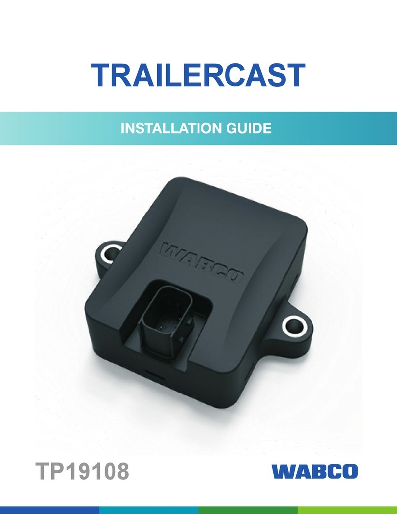
WABCO TP2205 User manual

TRAILERCAST WITH
BATTERY
TP2205
INSTALLATION GUIDE


3
Table of Contents
Table of Contents
1 General Information ....................................................................................................................................................5
1.1 Symbols Used in this Document ........................................................................................................................5
1.2 How to Obtain Additional Maintenance, Service and Product Information.........................................................6
1.3 How to Obtain Parts and Kits.............................................................................................................................6
1.4 WABCO TOOLBOX PLUS™ Software ..............................................................................................................6
1.5 WABCO Academy..............................................................................................................................................6
1.6 WABCO Online Product Catalog .......................................................................................................................6
1.7 Your Direct Contact to ZF CVS ..........................................................................................................................7
2 Safety Information.......................................................................................................................................................8
2.1 Provisions for a safer work environment............................................................................................................8
3 Important Information.................................................................................................................................................9
4 Before the Installation ..............................................................................................................................................10
4.1 Liability .............................................................................................................................................................10
4.2 Approvals .........................................................................................................................................................10
4.3 Best Practices in Installation ............................................................................................................................ 11
5 Introduction - Hardware Components.....................................................................................................................13
6 Installation – TRAILERCAST with Battery Position ...............................................................................................15
6.1 General Recommendations .............................................................................................................................15
6.2 Preferred Installation (Standard Trailer with Fixed Trailer Bed) .......................................................................15
6.3 Alternative Installation (in Case of Trailer without Fixed Trailer Bed)...............................................................16
6.4 Preferred Installation for TRAILERCAST with Battery: Between Axle 2 and 3, Connector Upwards and to
Back of the Trailer ............................................................................................................................................17
Front of the Trailer............................................................................................................................................18
7 Fastening TRAILERCAST with Battery ...................................................................................................................20
7.1 Fixing the bracket to the Trailer........................................................................................................................20
7.2 Fixing the TRAILERCAST with Battery to the Bracket.....................................................................................20
8 Fastening TRAILERCAST with Battery (when Bracket is not used) ....................................................................22
9 Connecting Hardware ...............................................................................................................................................23
9.1 Hardware Activation .........................................................................................................................................23
9.2 Connection to TRAILERCAST with Battery for iABS or RSSplus ...................................................................23
10 WABCO iABS Subsystems.......................................................................................................................................26
10.1 Hardware Connection ......................................................................................................................................26
11 WABCO RSS Subsystems........................................................................................................................................28

11.1 Hardware Connection ......................................................................................................................................28

4
Edition 1
Version 1 (10.2022)
TP2205 (en)
This publication is not subject to any update service. Information contained in this
subject to change without notice or liability. ZF CV Systems North America LLC reserves
the right to revise the information presented or to discontinue the production of parts
described at any time.
https://zf.com/cvliterature
12 Connecting to the Internal Sensors ........................................................................................................................29
12.2 Connecting to the Internal Sensors (SMS) ......................................................................................................29
12.3 WABCO TPMS Manager .................................................................................................................................30
......................................................................................................31
13 Assembly of the Internal Sensor SMS ....................................................................................................................33
13.1 Safety Information............................................................................................................................................33
13.2 Preparing the Installation .................................................................................................................................34
13.3 Installation of the Internal Sensor ....................................................................................................................34
13.4 Assembly of the Tire ........................................................................................................................................36
13.5 Assembly of the Wheel ....................................................................................................................................37
14 Checking the Installation..........................................................................................................................................38
14.1 Installation Wizard............................................................................................................................................40
15 Appendix I..................................................................................................................................................................45
15.1 Vehicle Electrical Grounding Guidelines ..........................................................................................................45
16 Appendix II ................................................................................................................................................................46
16.1 Parts and Variant List.......................................................................................................................................46

5
General Information
1 General Information
1.1 Symbols Used in this Document
DANGER
Description of an immediate situation which may result in irreversible injury or death if the warning is
ignored.
WARNING
Description of a possible situation which may result in irreversible injury or death if the warning is
ignored.
CAUTION
Description of a possible situation which may result in irreversible injury if the warning is ignored.
NOTICE
Description of a possible situation which may result in material damage if the warning is ignored.
Important information, notices and/or tips
Reference to information on the Internet
Descriptive text
– Action step
Action step 1 (in ascending order)
Action step 2 (in ascending order)
• Listing
Indicating the use of a tool / WABCO tool

6
General Information
1.2 How to Obtain Additional Maintenance, Service and Product
Information
If you have any questions about the material covered in this publication, or for more
information about the WABCO product line, please contact WABCO Customer Care Center
www.zf.com/cv.
documents and standards applicable to WABCO products (such as SAE J447 and SAE
J908 at www.sae.org).
current documents referenced in the manual at www.nhtsa.gov.
1.3 How to Obtain Parts and Kits
Contact the WABCO Customer Care Center at 855-228-3203 (United States and
1.4 WABCO TOOLBOX PLUS™ Software
TOOLBOX PLUS™ Software provides PC diagnostic for WABCO products and can be
purchased and downloaded from https://wabco.snapon.com.
The software User Guide, MM19047 can be obtained by visiting our Literature Center.
Purchase and Download TOOLBOX PLUS™
https://wabco.snapon.com
ZF Commercial Vehicle Literature Center
https://zf.com/cvliterature
1.5 WABCO Academy
www.wabco-academy.com
1.6 WABCO Online Product Catalog
www.wabco-customercenter.com

8
Safety Information
2 Safety Information
2.1 Provisions for a safer work environment
vehicle.
Read this publication carefully
Follow all warnings, notices and instructions to help avoid personal injury and property damage.
Observe all accident regulations of the respective company as well as regional and national regulations.
Use personal protective equipment if required (safety shoes, protective goggles, respiratory protection
and ear protectors).
Read and observe all Danger, Warning and Caution hazard alert messages in this publication. They provide
information that can help prevent serious personal injury, damage to components, or both.
WARNING
To help prevent serious eye injury, always wear eye protection when you perform vehicle maintenance or
service.
WARNING
Park the vehicle on a level surface. Block the wheels to help prevent the vehicle from moving. Support the
vehicle with safety stands. Do not work under a vehicle supported only by jacks. Jacks can slip and fall
over. Serious personal injury and damage to components can result.
WARNING
This product can expose you to chemicals including Nickel, which is known to the State of California to
cause cancer and birth defects or other reproductive harm. For more information, go to
www.P65Warnings.ca.gov.

9
Important Information
3 Important Information
Use only genuine WABCO components. Other manufacturers’ parts are not designed for use with a
WABCO TRAILERCAST system and it may not function correctly.

10
Before Installation
4 Before Installation
This installation guide provides you with installation directives and procedures for the installation of
TRAILERCAST with Battery.
4.1 Liability
Service Partner or by the customer (after ZF training/demo installation). Contact your service partner in
case the iABS/RSSplus data still needs to be activated.
Many customers prefer to do the installation themselves: the building-in of the device can then be combined
purpose, ZF provides training for the technical engineers of the installation company. The training consists
of a theoretical part which can be illustrated with a demo installation, and further monitoring. Afterwards, the
been found correct at the time this manual was composed. However, ZF cannot accept any responsibility
for possible adaptations by the manufacturer concerned. ZF aims for a continuous improvement of its
products. For the purpose of technical progress, we reserve the right to implement changes at any time,
without prior notice.
4.2 Approvals
4.2.1 FCC Approval
the US Federal Regulations.
4.2.2 CE Approval
the RED directive.
4.2.3 Mobile Phone Radiance
FREQUENCY RF OUTPUT POWER
LTE-FDD B1/B2/B3/B4/B5/B8/B12/B13/B18/B19/B20/B26/B28 23 dBm ± 2 dB (class 3)
LTE-TDD B39 (for Category M1 only) 23 dBm ± 2 dB (class 3)
GSM850 / EGSM900 33 dBm ± 2 dB
DCS1800 / PCS1900 30 dBm ± 2 dB

11
Before Installation
4.3 Best Practices in Installation
DANGER
Vehicle electrical grounding guidelines are included in Appendix I.
4.3.1 Assembly
The assembly of the parts must be done using the accessories provided. ZF cannot be held responsible
for any errors resulting from the use of other materials. ZF wishes to point out that activities which require
welding to the trailer, can cause damage to the electronics of the device. It is imperative that the device is
disconnected when carrying out such activities.
4.3.2 Wire Management
All the wire ways shall be smooth and free from sharp edges. Wires shall be protected, so they do not come
conductors.
4.3.3 Operating Conditions
Input voltage range: 10 - 32 V
Maximum current: 1.5 A
Operating temperature range – Externally powered -40°C ~ +75° C
Operating temperature range – Battery powered: -20°C ~ +60° C
Battery charging temperature range: 0°C ~ +45° C
Storage temperature range – Battery powered: -20°C ~ +60° C
Nominal power consumption – Battery fully charged: 0.6 W
Maximum power consumption – Battery charging: 7.5 W
Ingress protection: IP6K6K/IP6K9K
Compliance with: ISO 16750 – D/E – L – E - D - D – IP6K6K / IP6K9K

12
Before Installation
4.3.4 Disposal
4019842a
In case you no longer want to use the TRAILERCAST with Battery unit, it is prohibited to dispose of it
together with domestic waste as the system components are electronic scrap. Batteries are hazardous
waste.
Dispose of hazardous waste in an environmentally friendly manner and in compliance with relevant local,
state and federal regulations.
ZF strives to protect the environment. As with other old devices, all components can be returned to ZF.
4.3.5 Improper Use
NOTICE
USE THE DEVICE ONLY FOR ITS INTENDED PURPOSE! DO NOT OPEN THE TRAILERCAST
WITH BATTERY UNIT. DO NOT DRILL INTO THE DEVICE HOUSING!
device must be immediately taken out of service.
The device safety may be endangered when:
The temperature limits are exceeded
The device is visibly damaged.
NOTICE
IF THE DEVICE IS VISIBLY DAMAGED, IT MUST BE TAKEN OFF OF THE VEHICLE IMMEDIATELY
AND SENT BACK TO ZF.
All other instructions, notes and regulations in this operation manual must be closely followed.

13
Introduction - Hardware Components
5 Introduction - Hardware Components
TRAILERCAST with Battery is a trailer tracking device with an embedded SIM card, GSM antenna and
GPS antenna. It is designed for outside use. It has an RF antenna to be used for tire pressure monitoring.
It is designed to be installed under the trailer. TRAILERCAST with Battery connects to the trailer’s iABS or
RSSplus.
TRAILERCAST UNIT DIMENSIONS (L x W x H)
(Cf. Section 7 Fastening TRAILERCAST with Battery,
page 20)
Installation Bracket
In case the installation includes a TPMS system (with
internal sensors), an installation bracket must be used to
used, the installation brackets are not required.
Bracket Dimensions: 251.8 x 205 x 4 mm
Hardware Description: Front view
4019844c
iABS/RSSplus PORT
FIXING
POINTS
Back view
4019845b
AIR VENT
CF. NOTE
NOTE: Make sure that the air vent of the TRAILERCAST
with Battery unit is always accessible to air. Make sure
that nothing can block the air access of the air vent. (DO
NOT apply glue/tape/silicone along the edges of the unit.)
Mounting the unit on any bracket should not block the air
vent.

14
Introduction - Hardware Components
Side view
4019847a
Pin Assignment Device serial number: TPXX-XXXXXXXXXXXXXXX
All WABCO component part number information can be found in Appendix II.

15
Installation – TRAILERCAST with Battery Position
6 Installation – TRAILERCAST with Battery Position
6.1 General Recommendations
When installing TRAILERCAST with Battery, keep the area around the antennas away from metal or
other obstructions as much as possible to avoid signal disturbance.
the unit with a ZF technician before deploying on a large scale.
Verify the installation with an external power source connected to the TRAILERCAST with Battery unit.
To obtain a full battery capacity, connect the TRAILERCAST with Battery unit to an external power
source for 4 hours.
Make sure that the unit will not be continuously exposed to direct sunlight.
Make sure that the label of the unit is always visible.
The installation technician remains responsible at all times for the correct installation and connection of
the hardware unit.
has been received via . Check this for every
installation.
6.2 Preferred Installation (Standard Trailer with Fixed Trailer Bed)
In case the installation includes a Tire Pressure Monitoring System (TPMS) system (connecting to the
The unit must be installed below the trailer bed with the front of the TRAILERCAST with Battery unit
directed to the ground.
Make sure that the front of the unit has a clear view to the ground (not obstructed by other components).
Keep the sides of the unit at a minimum distance of 20 cm from obstacles.
using (Section 14 Checking the Installation,
page 38).

16
Installation – TRAILERCAST with Battery Position
6.3 Alternative Installation (in Case of Trailer without Fixed Trailer Bed)
In case the installation includes a TPMS system (connecting to the internal sensors), an installation
Find a suitable location and make sure that the front of the unit has a clear view as much as possible
(min. 150 cm).
Keep the sides of the unit at a minimum distance of 20 cm from obstacles (also keep a minimum
distance of 20 cm above the unit).
using (Section 14 Checking the Installation,
page 38).

17
Installation – TRAILERCAST with Battery Position
6.4 Preferred Installation for TRAILERCAST with Battery: Between
Axle 2 and 3, Connector Upwards and to Back of the Trailer
In case the installation includes a TPMS system (connecting to the internal sensors), an installation
Install the unit between axle 2 and 3, with the connector facing towards back of the trailer.
Make sure that the unit is placed with the connector on the upper side.
Install the unit at around 70 cm from the ground.
Install the unit centered between the wheels (in the middle of the axle).
Install the unit at a max. distance of 2.3 m from the center of any of the wheels.
If possible, make sure that the unit has a clear view to all wheels (not obstructed by other components).

18
Installation – TRAILERCAST with Battery Position
6.5 Alternative Installation for TRAILERCAST with Battery:
Between Axle 1 and 2, Connector Upwards and to the Front of
the Trailer
In case the installation includes a TPMS system (connecting to the internal sensors), an installation
Install the unit between axle 1 and 2, with the connector facing towards front of the trailer.
Make sure that the unit is placed with the connector on the upper side.
Install the unit at around 70 cm from the ground.
Install the unit centered between the wheels (in the middle of the axle).
Install the unit at a max. distance of 2.3 m from the center of any of the wheels.
If possible, make sure that the unit has a clear view to all wheels (not obstructed by other components).

19
Installation – TRAILERCAST with Battery Position
6.5.1 Incorrect Installation
INCORRECT: Do NOT install the unit on or inside the trailer beams.
4019853a
INCORRECT: Do NOT install the unit above other components (e.g., air tanks, etc.). The unit requires a
clear view to the ground.
4019854a
6.5.2 Installation Instructions for Cables
The general installation instructions to be observed for cables and connectors can be downloaded from:
http://inform.wabco-auto.com/intl/drw/9/4490000000.pdf.
After connecting all hardware to TRAILERCAST with Battery, ZF recommends using cable ties to relieve
tension from the connectors.

20
Fastening TRAILERCAST with Battery
7 Fastening TRAILERCAST with Battery
In case the installation includes a TPMS system (connecting to the internal sensors), an installation bracket
required.
Always install the TRAILERCAST with Battery unit in one of the recommended positions. (See General
recommendations for TRAILERCAST with Battery on p. 14.)
Always verify that sufficient GPS coverage is guaranteed and a good GPS position has been received
using (Section 14 Checking the Installation,
page 38). Check this for every installation!
Please observe the following recommendations:
Install the unit centered between the wheels (in the middle of the axle).
Make sure that the unit has clear view to all wheels (not obstructed by other components).
Install the unit at a max. distance of 2.3 m from the center of any of the wheels.
Install the unit at around 70 cm from the ground.
7.1 Fixing the bracket to the Trailer
Screw the bracket onto the trailer.
7.2 Fixing the TRAILERCAST with Battery to the Bracket
Use hexagon head M8 x 1.25. class 8.8 bolts, nuts and washers (not included) treated for the applicable
environment to mount the TRAILERCAST with Battery unit on the bracket.
Tighten with a maximum torque of 12.5 Nm.
Make sure that the unit is positioned with the connector on top, facing the underside of the trailer.
Table of contents
Other WABCO Automobile Accessories manuals

WABCO
WABCO OnGuard User manual

WABCO
WABCO iABS 2S/1M Standard User manual

WABCO
WABCO Truck Training Model User manual

WABCO
WABCO OnGuard User manual

WABCO
WABCO 2S/2M User manual

WABCO
WABCO OnSide MM16167 User manual

WABCO
WABCO OPTIFLOW SIDEWINGS User manual

WABCO
WABCO TP0735 User manual

WABCO
WABCO OnGuard User manual

WABCO
WABCO 971 002 923 2 User manual